Jindara Spectre User manual

Operation & Installation Instructions
Spectre Module
Please keep these instructions for future reference.Rev *
Spectre Module 16
AF Gason Pty. Ltd. reserves the right to modify or alter specications, material, etc. in the interest of product improvement.
WARRANTY
1. Subject to clauses 2 & 3 of this warranty, A.F. Gason Pty Ltd ACN 004 667 556 warrants the following components of its heaters against defects in workmanship
and/or materials for the following periods from the date of purchase:
a) the rebox for ten years;
b) the paint nish for a period of 12 months if the purchaser has followed the instructions provided by Gason in the operation and Installation Instructions manual; and
c) all other components for 12 months except the glass, re brick lining or bae plate if, in the opinion of Gason, these items have been damaged by impact.
2. This extended warranty does not apply;
a) if the heater is purchased from a person who has not been authorised by Gason to sell its products;
b) if, in the opinion of Gason, the heater or any other component has been subject to abuse, misuse, alteration, modication or has not been installed, operated or maintained in
accordance with the instructions provided by Gason; or,
c) to owners other than the original purchaser.
3. If you believe that the heater you purchased contains a manufacturing defect and you wish to make a claim under this warranty, please contact an authorised Gason servicce
centre to arrange for an assessment.
4. If, after assessing the heater, Gason determines that the heater contains a manufacturing fault, Gason may at its discretion:
a) replace the heater;
b) repair or replace specic components of the heater; or
c) provide a full refund.
5. Parts replaced under warranty are warranted for the balance of their original warranty period.
6. If, at the discretion of Gason, the heater or any part needs to be replaced, serviced or repaired at an authorised Gason service centre, then the person claiming under this
warranty must pay all costs associated with:
a) returning the heater; and
b) the delivery or collection of any new or repaired heater.
Our goods come with guarantees that cannot be excluded under the Australian Consumer Law. You are entitled to a replacement or refund for a major failure and for
compensation for any other reasonably foreseeable loss or damage. You are also entitled to have the goods repaired or replaced if the goods fail to be of acceptable quality
and the failure does not amount to a major failure.
Any benets you receive under these warranties are in addition to other rights and remedies that you may have as a consumer under law in relation to the heater to which
these warranties relate.
These warranties are given by:
AF Gason Pty Ltd
Blake Street
Ararat VIC 3377
Please contact us if you have any queries on:
Phone: 03 53522151
or email us via the “Contact Us” section of our website: www.gason.com.au
234965

Spectre Module 2 Spectre Module 15
Troubleshooting (Continued)
Read and follow these instructions carefully before installing and
u
sing this appliance.
WARNING
!
WARNING
!
Safety Warnings
• A ue re with resulting damage may occur if the appliance is not installed,
operated and maintained as per this booklet.
• Never place combustible materials such as wood, paper or furniture near the
appliance.
• This appliance is designed to burn dry wood. Do not burn rubbish, driftwood,
flammable liquids or any substance containing salts or corrosives.
• This appliance must not be installed and operated in an area where kerosene,
petrol, paint thinner or other ammable liquid is used or stored.
• The ue system must be inspected and cleaned annually or sooner if required.
Failure to do so could result in an excessive buildup of creosote which may
result in a ue re, which may damage the ue or cause damage to your home.
• The surface of the appliance becomes hot during operation. Do not touch the
surface of this appliance. Keep children away from this appliance during
operation. Do not allow anyone to operate this appliance who is not familiar
with this instruction booklet.
WARNING
!
Paint Curing and Care
Your heater is coated with the best available heat resistant paint. Even though
t
he paint has been baked after application, it may require further temperature
c
uring. It may, if you overre the heater on its rst re, discolour. For your rst
t
wo or three rings, never exceed Medium air setting and always have the fan
o
n when above low burn. Do not wipe the heater while the paint is curing. After
t
he paint has cured the only maintenance required to maintain the heater’s nish
i
s to wipe it with a soft cloth. Do not use any commercial cleaners or solvents on
t
he paint nish.
W
e are proud of the presentation of our products. If at any time you need to
f
reshen up the paint, your local dealer has touchup paint available for purchase.
Y
ou may even change the colour of your heater if you wish.
If you have any enquiries, please contact the dealer from whom you purchased your heater:
P
LEASE COMPLETE:
D
ealer Name:
D
ealer Address:
Phone:
P
lease attach your original purchase dockets to this booklet for future reference.
To aid heater installation, remove door, bae system and cast iron liners to reduce
overall heater weight.
This heater is painted in stovebrite Metallic Black - code 6309.
Dealer Email:
Removing heater from pallet:
• Remove front ll panels on either side of the appliance by backing o 2x retaining screws and lifting up.
• Remove 4x tek-screws holding appliance to transport pallet.
• Re-t l panels and re-tighten retaining screws.
O/All weight: 240kg
Package dimensions: 950Hx910Wx770D
To aid heater installation, remove doors, top plate, bae and cast iron liners to reduce overall heater weight.
Figure 14
0$7(5,$/
),1,6+
'5$:1
7,7/(
$33'
-,*
6+((7
2)
5(9
%<
(&11R
'$7(
5(9
%<
(&11R
'$7(
5(/($6('
'21276&$/(
$
6&$/(
3$571R
02'8/($66(0%/<
(85(.$-(:(/-,1'$5$63(&75(
77
(1*35
7+,6,1)250$7,21,6&21),'(17,$/$1'5(0$,167+(
3523(57<2)$)*$62137</7'81'(5&23<5,*+7/$:
$)*$62137</7',1&,19,&725,$
5(*,67(5('2)),&(
%/$.(675((7$5$5$7
9,&725,$
0$66NJ
7+,5'
$1*/(
352-(&7,21
67$1'$5'0(75,&72/(5$1&(681/(6663(&,),('27+(5:,6(
',0(16,2166+2:17+86RU
'5,//('+2/(6381&+('+2/(6$1*/(6
)25/$6(5&87&20321(176
)256+((7PP$1'81'(572/(5$1&(
)256+((7WRPP72/(5$1&(
77
745
Door to door
841
Total width
692
695
653
0$7(5,$/
),1,6+
'5$:1
7,7/(
$33'
-,*
6+((7
2)
5(9
%<
(&11R
'$7(
5(9
%<
(&11R
'$7(
5(/($6('
'21276&$/(
$
6&$/(
3$571R
02'8/($66(0%/<
(85(.$-(:(/-,1'$5$63(&75(
77
(1*35
7+,6,1)250$7,21,6&21),'(17,$/$1'5(0$,167+(
3523(57<2)$)*$62137</7'81'(5&23<5,*+7/$:
$)*$62137</7',1&,19,&725,$
5(*,67(5('2)),&(
%/$.(675((7$5$5$7
9,&725,$
0$66NJ
7+,5'
$1*/(
352-(&7,21
67$1'$5'0(75,&72/(5$1&(681/(6663(&,),('27+(5:,6(
',0(16,2166+2:17+86RU
'5,//('+2/(6381&+('+2/(6$1*/(6
)25/$6(5&87&20321(176
)256+((7PP$1'81'(572/(5$1&(
)256+((7WRPP72/(5$1&(
77
256
971

Spectre Module 14 Spectre Module 3
Installation
WARNING
!
Installation
THE INSTALLATION OF THIS APPLIANCE MUST BE CARRIED OUT AS PER THIS
MANUAL AND THE FLUE MANUFACTURER’S SPECIFICATIONS.
WE RECOMMEND THAT YOU USE A QUALIFIED INSTALLER TO CARRY OUT
THE INSTALLATION.
If you have any other enquiries, please contact the dealer from whom you
purchased your heater.
THIS APPLIANCE WEIGHS IN EXCESS OF 220 KILOGRAMS. EXTREME CARE
SHOULD BE TAKEN WHEN HANDLING THE APPLIANCE.
AF Gason Pty. Ltd. accepts no liability whatsoever for any interpretation of AS/NZS 2918:2001.
It is important you understand these installation instructions and minimum clearances to combustible materials before
selecting a position for your Jindara Spectre to ensure safe and correct installation is achieved.
Installation permit
Depending on your local authority requirements, a permit may be required for the installation of your heater. It is your
responsibility to arrange the same.
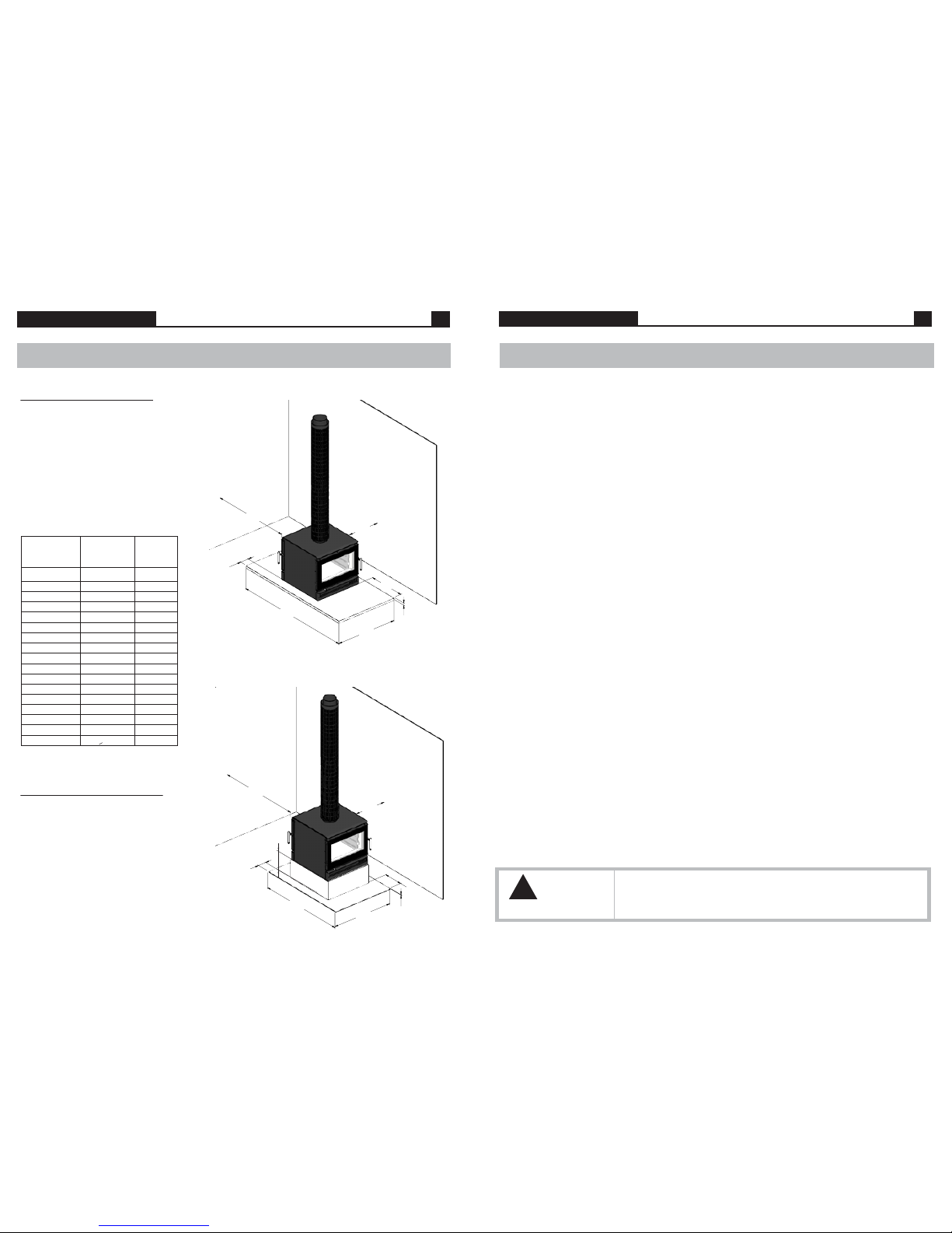
Flue requirements
As per the dimensions in Figure 1, the Jindara Spectre can be installed with a Perforated 7” Default Flue Kit, or Figure 2,
a Solid 7” Default Flue Kit. In both instances, an additional 8” solid ue must be tted between the inner ue and outer
ue, to the height of the ceiling if any part of the unit is to be installed less than 1200mm from a heat sensitive surface.
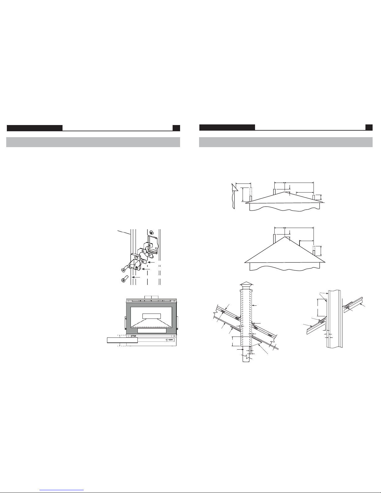
The ue system installed with the Jindara Spectre must comply with Australian and New Zealand installation
standards AS/NZS 2918:2001, and be installed to the ue manufacturer’s instructions.
The performance of your Jindara Spectre is highly reliant on an eective ue system. In many cases poor start-up, dirty glass,
down draft which causes smoking when the door is open, and a reduction in heat outupt can all be related to the ue system
being too short, or incorrect installation. Too tall a ue can result in excess draft and short burn times along with excessive
heat output.
Clearance to combustibles
The Jindara Spectre module heater conforms to AS/NZS 2918:2001 when positioned in relation to combustible surfaces
as shown in Figures 1 & 2 on the following page. All dimensions used in this document are in millimetres and are minimum
unless otherwise stated.
These dimensions in Figures 1 & 2 state the minimum distance the Jindara Spectre can be placed in relation to any
combustible materials - plaster, wallpaper, timber, MDF, etc.
In the instance your Jindara Spectre is surrounded by non-combustible materials - brick, stone, concrete, cement sheet,
villaboard or similar, wall clearances can be reduced to 50mm. A 50mm clearance is required to ensure room air can
circulate around the wood heater during operation.
For additional clearance details, or to access the Jindara Spectre Freestanding Conformance Certicate, please contact the
Jindara Dealer from whom you purchased your heater.
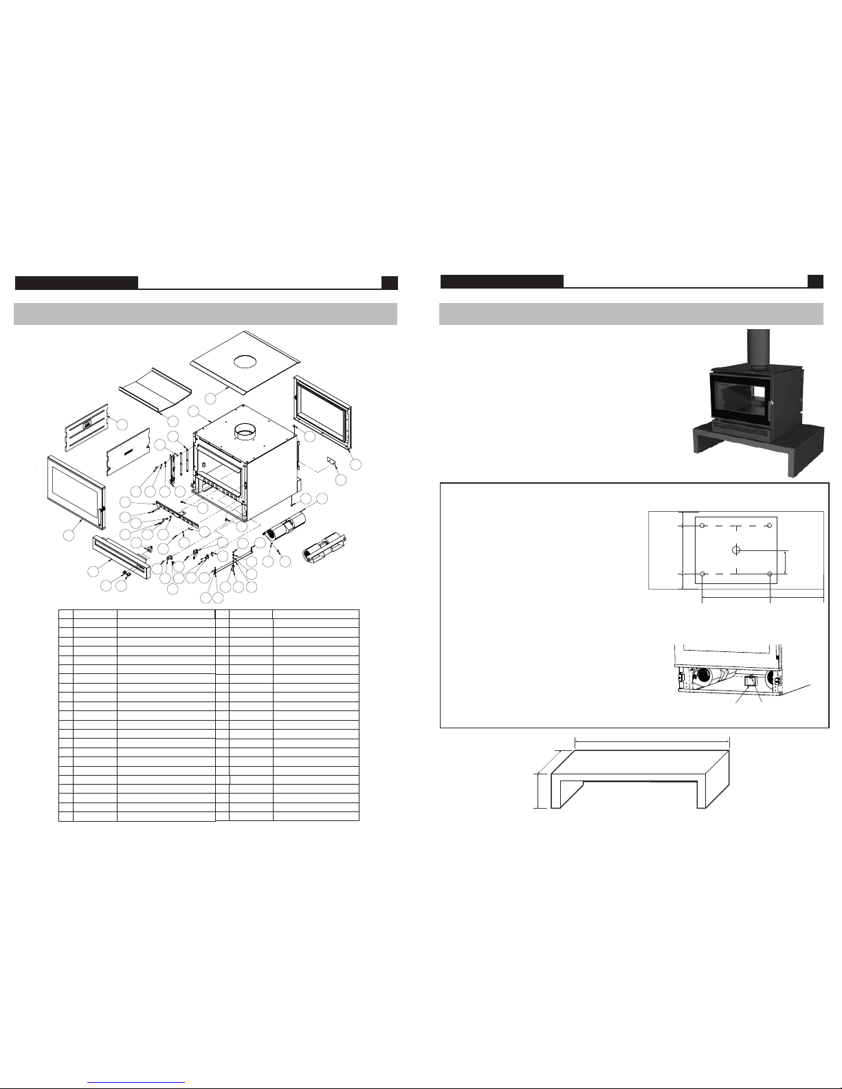
Hearth & oor requirements
If the Jindara Spectre will be installed onto a non-combustible oor such as a brick, stone or concrete slab with tiles, etc.
which is at least 32mm thick, and extends at least 570mm in front of the appliance base at each door, a hearth or oor
protector may not be required.
If the Jindara Spectre is to be installed onto a combustible oor, a minimum 32mm Bellis Board, or similar non-combustible
hearth or oor protector must be placed in between the appliance and the combustible oor. At a minimum, the oor
protector must extend570mm in front of the appliance base in both directions, with a minimum overall depth of 1890mm.
The protector must be at least 940mm wide.
Firewood
Getting the most out of your rewood
Firewood is a sustainable source of energy and when used correctly can provide a cost eective form of heating in your
home. Too often poor heating results and operational issues are attributed to using unseasoned wood which leads to
excess smoking, causing creosote buildup and dirty glass. Wood should be stored in a dry place where good ventalition is
available. Freshly cut wood should be stored for between 12-24 months before burning.
Use only hardwood with your Jindara Spectre.
Thermal eciency
A wood’s eciency does not depend only on its type, but also on its moisture content as well as the temperature of the
combustion chamber. To achieve a greater eciency and longer burn cycle out of your Jindara Spectre, without the emissions
of hazardous particulates, your wood must be well seasoned.
Ideally, wood should not be burnt when its moisture content is above 20%. A moisture meter to measure moisture content
is a handy addition.
0% moisture
100% thermal eciency
10% moisture
88% thermal eciency
30% moisture
63% thermal eciency
50% moisture
39% thermal eciency
An example of available thermal eciency for a piece of wood as a fuel source at varying moisture levels.
The combustion process of burning wood
When wood is heated up to approximately 100 degrees celsius, moisture begins to evaporate from the fuel. There is no
heating value from the wood at this point. As moisture releases from the wood, it reduces the eciency of the combustion
process robbing heat energy from the wood. This demonstrates the importance of dry and well seasoned wood.
As rebox temperatures reach 250-300 degrees celsius, wood solids begin to break down and release volatile gases which
ignite and produce heat.
From 300+ degrees celsius, the main energy available from wood is released when fuel vapors containing up to 60% of
the wood’s potential heat is released.
Understanding combustion principles and learning how to manipulate various conditions surrounding the operation of
your Jindara Spectre enables you to achieve maximum comfort and eciency from your Australian made wood heater.
Figure 13

Spectre Insert 4 Spectre Insert 13
0$7(5,$/
),1,6+
'5$:1
7,7/(
$33'
-,*
6+((7
2)
5(9
%<
(&11R
'$7(
5(9
%<
(&11R
'$7(
5(/($6('
'21276&$/(
$
6&$/(
3$571R
,1%$66(0%/<
(85(.$-(:(/-,1'$5$63(&75(
77
(1*35
7+,6,1)250$7,21,6&21),'(17,$/$1'5(0$,167+(
3523(57<2)$)*$62137</7'81'(5&23<5,*+7/$:
$)*$62137</7',1&,19,&725,$
5(*,67(5('2)),&(
%/$.(675((7$5$5$7
9,&725,$
0$66NJ
7+,5'
$1*/(
352-(&7,21
67$1'$5'0(75,&72/(5$1&(681/(6663(&,),('27+(5:,6(
',0(16,2166+2:17+86RU
'5,//('+2/(6381&+('+2/(6$1*/(6
)25/$6(5&87&20321(176
)256+((7PP$1'81'(572/(5$1&(
)256+((7WRPP72/(5$1&(
77
Installation
Parallel Installation - At Bench Height
- Refer to gure 2:
7” Active Flue with an 8“ solid ue and a 9”
Perforated or Solid painted outer ue casing,
which extends from the top of the heater to
the drop box at the ceilling level.
Dimensions shown are minimum only, when
installed at bench height.
(continued)
Figure 1
Installation
Operating your Jindara
Troubleshooting
• Noisy Fans
Turn the power o and remove the three pin plug from the power point. Remove the door on one side of the unit,
then remove the fascia panel. Loosen the fascia ll panel retaining screws and lift panel up then out to remove.
Note that wiring and switches are atached to this panel. on one side.
Disconnect the wiring loom via the plastic joiner. Unscrew the wing nuts which hold each fan in position and remove
the fans. Clean any dust with a dry paint brush and vacuum the fan blades. Clean around the motor. After completion
place two or three drops of sewing machine oil on the shafts at the bearings. Replace the fans in reverse to the removal.
•Fans not working
and both switches are rmly connected. If the fans still fail to function, remove the fans and switches by rstly removing
the knob from the rotary switch by pulling it away from the heater. Undo the holding nut and pull the switch out.
Squeeze locator tabs together on the rear of the thermostat switch and push through outside of pedestal.
Disconnect the wiring from the power lead and remove the fans. Convey the same to the authorised Jindara dealer from
whom you purchased your unit for service. Replace in the reverse order.
• Air control jamming
Access to the airside is available when the door is opened.
There are three screws holding the air slide in place. Undo them and remove the air slide.Wipe any ash or dust that may
have accumulated on the back of the air slide or on the face of the heater. If any burrs have developed on the back of the
air slide or on the face of the heater, rub them o with ne wet and dry sand paper till you have a smooth surface and
edges. Replace the air slide and make sure the washers, springs and spacers are tted when you screw the bolts back into
the face of the heater. Do not apply any type of lubricant to the air slide whatsoever as this will attract dust and make the
slide stick.
• No overnight burn
Remove the air slide as per air control jamming and check if the air slide is hard against the face of the heater. If it is
loose, tighten up the bolts holding the air slide to the face of the heater. Do not overtighten.
Check that the door rope has an even indentation from its contact with the face of the rebox. If it is uneven
and it appears as though air could leak through the seal,the door hinge and latch can be adjusted or the door rope may
need to be replaced. Refer door adjustments and rope replacement instructions.
WARNING
!
Overring
TO PREVENT OVERFIRING OF THE HEATER, NEVER OPERATE THE HEATER WITH THE
DOOR LOOSE, OR SUCH THAT THE FIREBOX IS NOT AIR TIGHT. OVERFIRING COULD
RESULT IN DETRIMENTAL WEAR AND TEAR ON THE FIREBOX AND FLUE SYSTEM.
Check the power connection with another appliance. If the power point is O.K. shift focus to the fan or the switches.
Move thermostat switch into the ‘Overide’ position, and select one of the three fan speeds. If the fans fail to function,
isolate power as above, remove pedestal ller panel to gain access to loom. Check that the terminals on the loom
• Excessive ash build up
Some woods will give large amounts of ash despite how you run the heater. Others will give you very little. Use the wood
which is most convenient for you, as long as it is dry. After a period of time you will get to know when to empty your unit.
Bark will give you excessive ash. Try not to burn it. If you are burning wood that gives you charcoal, you may nd that after
running the heater say for 8 hours at maximum burn rate, the charcoal builds up excessively. An overnight burn will reduce
this charcoal back to a ne ash. If you are not ready to shut down for an overnight burn when you next fuel the heater, load
the heater with only one piece of wood and lay it across the rebox on top of the charcoal. Open the air control wide open
and you will nd the charcoal will burn down with the one piece of wood. Repeat the process until the ash level is
signicantly reduced.
• Excessive smoking - smoke entering the room maybe caused by:
• Insucient length of ue (ue to be 4500mm minimum underneath the base of heater to underside of cowl)
Increase height of ue
• Flue downdraught - Consult dealer or increase height of ue.
• Creosote build up in ue - Remove cowl and clean ue as per cleaning instructions. Check moisture content of
wood.
Parallel Installation - At Floor Level
- Refer to gure 1:
7” Active Flue with an 8“ solid ue and a 9”
Perforated or Solid painted outer ue casing,
which extends from the top of the heater to
the drop box at the ceilling level.
Dimensions shown are minimum only, when
installed at oor level. Hearth reductions for
elevated installations are shown in table 1.
0$7(5,$/
),1,6+
'5$:1
7,7/(
$33'
-,*
6+((7
2)
5(9
%<
(&11R
'$7(
5(9
%<
(&11R
'$7(
5(/($6('
'21276&$/(
$
6&$/(
3$571R
02'8/($66(0%/<
(85(.$-(:(/-,1'$5$63(&75(
77
(1*35
7+,6,1)250$7,21,6&21),'(17,$/$1'5(0$,167+(
3523(57<2)$)*$62137</7'81'(5&23<5,*+7/$:
$)*$62137</7',1&,19,&725,$
5(*,67(5('2)),&(
%/$.(675((7$5$5$7
9,&725,$
0$66NJ
7+,5'
$1*/(
352-(&7,21
67$1'$5'0(75,&72/(5$1&(681/(6663(&,),('27+(5:,6(
',0(16,2166+2:17+86RU
'5,//('+2/(6381&+('+2/(6$1*/(6
)25/$6(5&87&20321(176
)256+((7PP$1'81'(572/(5$1&(
)256+((7WRPP72/(5$1&(
77
1275
475
280
123
300
6
1375
940
0$7(5,$/
),1,6+
'5$:1
7,7/(
$33'
-,*
6+((7
2)
5(9
%<
(&11R
'$7(
5(9
%<
(&11R
'$7(
5(/($6('
'21276&$/(
$
6&$/(
3$571R
02'8/($66(0%/<
(85(.$-(:(/-,1'$5$63(&75(
77
(1*35
7+,6,1)250$7,21,6&21),'(17,$/$1'5(0$,167+(
3523(57<2)$)*$62137</7'81'(5&23<5,*+7/$:
$)*$62137</7',1&,19,&725,$
5(*,67(5('2)),&(
%/$.(675((7$5$5$7
9,&725,$
0$66NJ
7+,5'
$1*/(
352-(&7,21
67$1'$5'0(75,&72/(5$1&(681/(6663(&,),('27+(5:,6(
',0(16,2166+2:17+86RU
'5,//('+2/(6381&+('+2/(6$1*/(6
)25/$6(5&87&20321(176
)256+((7PP$1'81'(572/(5$1&(
)256+((7WRPP72/(5$1&(
77
1275
123
1890
475
570
940
32
MinimumAppliance
Hearth Dept raised by
X Y
Table 1. Appliance height
vs hearth requirements
570
553
530
505
478
448
433
420
416
398
379
359
338
315
300
300
Elevated installation details
(dimensions in mm)
0
20
40
60
80
100
110
118
120
130
140
150
160
170
176
>176
H
Minimum
Hearth
Thickness
32
32
32
32
32
32
32
6
6
6
6
6
6
6
6
6
Figure 2

Spectre Module 12 Spectre Module 5
Removing the fascia
• Turn the fan power off, and removed the three pin plug from the power point.
• Open the door 25mm and lift door off hinge, place door on a soft flat surface.
• Undo x4 M8 button head cap screws which attach the fascia to the main firebox.
• Gently lift the fascia away from the front of firebox, but do not pull away fascia completely, leave the fascia rest on the hinge while
removing the fan switches.
• With the fascia resting on hinge, reach behind the switch panel and undo x2 wing nuts and remove switch panel.
• With switch panel removed, fascia can now be completely moved away from the heater to gain access to the fan and wiring looms.
Installation (Continued)
The Jindara Spectre Module can be installed into various installations depending
on desire, or practicality. Figure 3 shows the appliance when installed
on a Bench. Use this image as a guide for inspiration, or installation tips.
All installations must conform as per dimensions on page 4, when installing on
or adjacent to combustible materials.
Under all circumstances, if installing the Jindara Spectre Module on a bench above a
oor comprising of combustible material, a minimum 6mm thick non-combustible
oor protector centred to the appliance at least 940mm wide, must extend 300mm
in front of the bench, and continue beneath the bench to meet the rear of the bench
or rear wall of the installation to conform to AS/NZS 2918:2001.
Take care not to scratch hearth, or bench during the installation process.
The bench is tted with x4 levelling feet which will allow for any hearth or oor
unevenness.
1200
280
775
1200 Two Door Bench
Module Footprint (top view)
Hole centres for xing to bench
FRONT OF BENCH - APPLIANCE LOCATED CENTRALLY
97.5
580
260
97.5
Fixing Module to Bench
• With Module on pallet, back off 2x retaining screws and remove
pedestal filler panel (each side) to gain access to transport screws.
• Remove tek screws holding base of the appliance to the pallet.
• Using the Module footprint dimensional guide (figure 4), mark
out the transport bracket hole centre on the bench.
• Double check the hole centre dimensions by measuring the
existing hole positions in the base of the module before drilling.
• Upon confirming centre hole dimensions, drill 4x holes using a
4.5mm diameter drill bit. Remove all swarf when complete.
• If it is desired that the power cord should exit through the base
of the unit, a hole saw must be used (minimum 50mm diameter)
to create a hole as shown.
• Carefully removed Module from pallet, and locate on bench
over drilled holes. (Remove top plate, door, cast iron liners and
baffle system to reduce overall appliance weight)
• Using 4x supplied tek screws, attach Module to bench.
• If central hole has been cut, use pinch weld supplied to cover the
edges of the hole, to protect the power cord from damage.
Note: Do not pass the power cord through the hole in the centre
until after all four retaining screws have been fitted and the pinch
weld is installed.
• Secure the power cord to in the base of the unit using the cord
grip grommet, as shown in figure 5.
Figure 3
Basic Spare Parts
1
2
3
4
5
6
7
8
9
10
11
12
13
14
15
16
17
18
19
20
21
22
23
24
25
26
27
28
29
30
31
32
33
34
35
36
37
38
39
40
41
42
43
44
234933
230980
907424
917333
922334
230565
903903
234278
231030
233881
232037
213049
227074
906103
234101
910106
234016
234015
213151
906201
213146
917119
233884
230568-10
230980
907424
917333
922334
230565
203903
234278
231030
233881
232037
231049
227074
204184
906103
213321
221328
203651
234101
214289
213098
907400
212974
917209
234811
204184
203902
234935
233880
234936
231804
223625
231821
917203
903206
233882-01
233883-01
208177
903205
234939
203651
234016
234015
213151
906201
213164
917119
214289
213098
907400
212974
917209
231804
233882-01
233883-01
917203
903206
234811
203902
208177
903205
Ref. GPN Description Ref. GPN Description
Module Assy
Hinge
Washer Flat 8 x 20
Screw Set M8 x 20
Screw Cap M8 x 20
Door Assembly
Twin Barrel Fan
Blanking Panel
Cast Iron Liner
Steel Bae Plate
Switch - 2 Position
Switch - 3 Position
Switch Knob
Washer Flat 3/16” x 9/16”
Hinge Shim
Washer Star M8
Latch Block Shim
Catch Assembly
Screw Tek 10-16 x 16
Washer Flat 1/4“ x 3/4”
Wing Nut M6
Screw Set M5 x 20 C/S
Fascia Assy
Fascia Fill Panel
Hinge
Washer Flat M8 x 20
Screw Set M8 x 20
Screw Cap M8 x 20
Door Assembly
Twin Barrel Fan
Blanking Panel
Cast Iron Liner
Steel Bae Plate
Switch - 2 Position
Switch - 3 Position
Switch Knob
Air Slide Bush
Washer Flat 3/16” x 9/16”
Rubber Grommet
Rubber Grommet Blank
Grommet Cord Grip
Hinge Shim
Thermostat Switch
Air Slide Spacer
Washer Flat 10 x 18
Air Slide Spring
Screw Set M6 x 20
Air Slide Link Spacer
Air Slide Bush
Screw Tek 10-16 x 25
Lower Inll Assembly
Top Panel
Inll Mount Bracket
Air Slide Rod
Rubber Bumper - Lower
Rubber Bumper - Upper
Screw Set M6 x 25
Nut Whiz Lock M6
Air Slide Panel
Air Slide Linkage
Screw Set M5 x 15
Nut Whiz Lock M5
Cord Grip Bracket
Grommet Cord Grip
Washer Star M8
Latche Block Shim
Catch Assembly
Tek Screw 10 -16 x 16
Washer Flat 1/4”x 3/4”
Wing Nut M6
Screw Set M5 x 20 C/Sunk
Thermostat Switch
Air Slide Spacer
Washer Flat 10 x 18
Air Slide Spring
Screw Set M6 x 20
Air Slide Rod
Air Slide Panel
Linkage Panel
Set Screw M6 x 25
Nut M6
Spacer - Air Slide Linkage
Tek Screw 10-16x25
Screw Set M5x15
Nut M5
Figure 12
$
$
6(&7,21$$
6&$/(
$,56/,'(/,1.$*(,167$//$7,21
%207DEOH5HVWUXFWXUHG
,7(0 3$571R
'(6&5,37,21
47<
6,=(
3$,17/,1($66<
$
+,1*(
$
:$6+(5)/$766[[
6&5(:6(70[[3%/$&.
6&5(:&$30[%87+'
'225$66<
$
)$1$66<7:,1:+((/
%/$1.,1*3$1(/,1%
$
%207DEOH5HVWUXFWXUHG
,7(0 3$571R
'(6&5,37,21
47<
6,=(
&$67,521/,1(55($5
$
%$))/(3/$7(
$
6:,7&+326,7,2163'721
21
)$16:,7&+63(('527$5<
.12%32:(56:,7&+
$
:$6+(5)/$7[[*
+,1*(6+,0
$
:$6+(567$50
,17(5/2&.,1*=3
/$7&+%/2&.6+,0
$
&$7&+$66(0%/<
$
6&5(:7(.[6(/)7
:$6+(5)/$7[*=3
$
187:,1*0=3
6&5(:6(70[&681.
%/$&.
6:,7&+7+(50267$7'(*
63$&(5$,56/,'(
$
:$6+(5)/$7[[PP
635,1*667((/$,56/,'(
6&5(:6(70[3+'%/$&.
63$&(5$,56/,'(/,1.$*(
$
%86+$,56/,'(
$
6&5(:7(.[6(/)7
,1),//:(/'$66(0%/<
$
7233$1(/67((/
$
,1),//02817%5$&.(7
$
52'$,56/,'(
$
*5200(7%8))(56
58%%(5%803(5%)
6&5(:6(70[[3+(;
*5=3
187:+,=/2&.)/$1*(066
3$1(/$,56/,'(
$
3$1(//,1.$*(
$
6&5(:6(70[32=,=3
1870:+,=/2&.)/$1*(
&/
&25'*5,3%5$&.(7
$
*5200(7&25'*5,3
0$7(5,$/
),1,6+
'5$:1
7,7/(
$33'
-,*
6+((7
2)
5(9
%<
(&11R
'$7(
5(9
%<
(&11R
'$7(
5(/($6('
'21276&$/(
$
6&$/(
3$571R
02'8/($66(0%/<
(85(.$-(:(/-,1'$5$63(&75(
77
(1*35
7+,6,1)250$7,21,6&21),'(17,$/$1'5(0$,167+(
3523(57<2)$)*$62137</7'81'(5&23<5,*+7/$:
$)*$62137</7',1&,19,&725,$
5(*,67(5('2)),&(
%/$.(675((7$5$5$7
9,&725,$
0$66NJ
7+,5'
$1*/(
352-(&7,21
67$1'$5'0(75,&72/(5$1&(681/(6663(&,),('27+(5:,6(
',0(16,2166+2:17+86RU
'5,//('+2/(6381&+('+2/(6$1*/(6
)25/$6(5&87&20321(176
)256+((7PP$1'81'(572/(5$1&(
)256+((7WRPP72/(5$1&(
77
470
290
%
%
6(&7,21%%
&
'(7$,/&
0$7(5,$/
),1,6+
'5$:1
7,7/(
$33'
-,*
6+((7
2)
5(9
%<
(&11R
'$7(
5(9
%<
(&11R
'$7(
5(/($6('
'21276&$/(
$
6&$/(
3$571R
02'8/($66(0%/<
(85(.$-(:(/-,1'$5$63(&75(
77
(1*35
7+,6,1)250$7,21,6&21),'(17,$/$1'5(0$,167+(
3523(57<2)$)*$62137</7'81'(5&23<5,*+7/$:
$)*$62137</7',1&,19,&725,$
5(*,67(5('2)),&(
%/$.(675((7$5$5$7
9,&725,$
0$66NJ
7+,5'
$1*/(
352-(&7,21
67$1'$5'0(75,&72/(5$1&(681/(6663(&,),('27+(5:,6(
',0(16,2166+2:17+86RU
'5,//('+2/(6381&+('+2/(6$1*/(6
)25/$6(5&87&20321(176
)256+((7PP$1'81'(572/(5$1&(
)256+((7WRPP72/(5$1&(
77
Fit pinch weld
to edge
Secure power cord
using cord grip grommet
Figure 4
Figure 5
Figure 6

6 Spectre Module 11
Spectre Module
Installation (continued)
Final inspection prior to use
• Ensure the baffle is firmly located and in the correct orientation.
• Ensure cast iron liners are positioned correctly.
• Check fan cord has not been damaged during transit.
• Plug in fan cord and ensure cord does not touch heater surface.
• Switch thermostat switch to ‘Override’ and select one of three speeds to
ensure fan is operational.
• Check door seals are in place.
Bae System
WARNING
!
Bae System
If the bae system is damaged, burnt out, discarded or not installed as per these
instructions, high ue temperatures, losses in combustion eciency and excess
smoking can occur.
To operate this appliance as it is intended, and to ensure product longevity is
achieved, ensure the bae is installed as per these instructions.
If rebox, ue failure or excess damage to the appliance or its surroundings is
reported due to incorrect installation or operation of the Insulated Bae System,
AF Gason Pty. Ltd. reserve the right to disallow any warranty or claims in relation to
the abovementioned.
Placement of Cast Iron Liners into rebox
The cast iron liners are to be positioned with ribs and logos facing into the
rebox.
To install cast iron liners, align the lower recesses of the cast iron liner and
the retaining tabs in the rebox, then slip the liner over the retaining tabs
and lower into position. Reverse this procedure for liner removal.
Fitting the steel bae
CAUTION - Steel bae is heavy (15kg) - seek assistance
when carrying out bae removal/installation.
1. Feed the baffle plate through the door opening
with the upturned edges facing towards the
door opening. Position the baffle in roughly the
centre of the firebox.
2. Lift one edge of the baffle up over the baffle
support bracket, lifting the raised edge as far
into the upper corner of the firebox as possible.
3. Lift the other edge of the baffle up so that it
is also above the height of the baffle support
brackets.
4. Shift the baffle sideways so that it locates in the
baffle supports on both sides of the firebox.
5. Ensure that the baffle is sitting level and that it
is securely located in the baffle supports.
Figure 6
Figure 3
Bae Support
Bracket
Steel Bae
Cast IronLiner
LinerRetaining Tabs
(continued)
Replacing your glass
• Open door and lift free of hinge.
• Place door face down on a soft flat surface to protect paintwork and glass.
• Remove glass retainers by removing 6x M6 whizlock nuts.
• Lift door frame away from glass. Note how the 6mm OD glass sealing rope is
placed around the door frame - dispose of old glass safely.
• Fit new 6mm OD glass sealing rope onto the door frame with new 14x dart
clips. Ensure outer corner and middle horizonal clips are positioned with the
pointed extrusion pointing outwards, with all other clips pointing inwards.
• Place the glass back onto the door frame with the 6mm OD door sealing rope in position.
• Fit glass retainers back to top and bottom of the door, and attach to door frame with the 6x M6 whizlock nuts. Tighten
nuts evenly until the retainer holds the glass. Do not over tighten the retainers as this could break the glass.
• Mount door back onto hinge, close and ensure fitment is safe and correct.
Fitting a new door seal
• Open door and lift free of hinge.
• Place the door face down on a soft flat surface to protect the paintwork and glass.
• Remove old rope and scrape old glue from rope retaining groove.
• Clean the rope retaining groove with a clean, dry cloth to remove any old dust and debris.
• Apply a generous bead of roof and gutter silicon around the rope retaining groove.
• Press the new 19mm OD door rope into the rope retainer groove, placing the start-stop joint to the bottom corner of the hinge
side of the door.
• Refit door and close to apply pressure to the new rope.
Note: Hinge and door catch may need to be adjusted to allow the door to close completely if previously adjusted to accommodate
an ageing rope.
• Leave door closed for at least 12 hours before lighting the heater, and initially run at a low temperature to allow adhesive
to fully bond to the door.
Maintaining & Servicing your Jindara
Figure 11
203603 Rope 19mm OD
230566 Door Frame
230922 Glass
230954 Retainer
231069 Rope 6mm OD
231070 Dart Clips
231805 Handle
903206 Nut Whizlock M6
904300 Nut Conlock M5
907204 Washer M6x12.5
907406 Washer 5.5x10x1
932202 Screw M6
231816 Shaft
231818 Latch
1
2
3
4
5
6
7
8
9
10
11
12
13
14
Ref. GPN Description

Spectre Module 10 Spectre Module 7
Installation (continued)
3000mm 3000mm
3000mm 1000mm
min if clear
within
3000mm of
ue top
Increase from
1000mm min
until clear
within 3000mm
of ue top
600mm min
More than 3000mm
600mm min
More than 3000mm
or less
3000mm
or less
Increase as
necessary
until
nothing
within
3000mm of
ue top
Any nearby
structure
3000mm
The ue pipe shall extend not less than 4.6m above the top of the oor protector. Note: Installation must be
carried out by a licensed installer in accordance with AS/NZS 2918:2001.
Flue pipe casing
Flashing
3 x ue diameter
from active ue to
heat sensitive
surface
Batten
Flue
pipe
Flashing
Flue pipe casings
Heat sensitive roof
25mm
25mm
25mm
Flue pipe
Gap 25mm
Gap 25mm
Roong
Batten
Ceiling
Ceiling Plate
See clause 4.6.3(b) of AS/NZS 2918:2001
25mm
12mm
25mm
178mm dia
Example of sloped ceiling penetration
Example of roof penetration
Rafter
See clause 4.8 of AS/NZS 2918:2001
Flue and chimney requirements
Figure 7
Figure 8
Maintaining & Servicing your Jindara
Catch Assembly
Latch Shim/s
Retaining Screws
Cleaning your ue
Firstly and carefully remove cast iron plates and bae system and put to one side. Close the heater door. Obtain a 180mm
ue brush from your local Jindara Dealer and proceed to the top of the ue. Remove the ue cowl. Slowly push the
brush down the ue until it stops. Pull the brush back out and repeat the process. Each time you do this you will notice
that the brush will go further down the ue until it reaches the bottom. The soot and creosote will fall down the ue and
into the rebox. Clean residue from rebox. Replace the bae platerst followed by the cast iron liners.
Make sure you do the job well.The cleaner the ue the less chance there will be of the creosote sticking again. After you
replace the cowl, inspect the roof ashing for any damage that may have incurred whilst you were cleaning the ue.
Reseal the seal on the roof with roof and gutter silicon if required.
Cleaning the glass
Generally the only time you will possibly need to clean your glass is after a long overnight burn. If you nd that you have
a wet sticky black lm on your glass (creosote), it is better to burn the heater as normal for one load of wood.When the
wood has burnt down to a hot bed of embers, open the door and leave it wide open until the glass cools suciently to
be wiped with a damp cloth.This should clean all the white smoky lm o the glass. Creosote on the glass is normally a
sign that you have tried to get too long an overnight burn or you have burnt excessively wet or green wood. If the lm on
the glass won’t come o with a wet cloth, you can use wet ash from the ash bed as a cleaner or commercial products
such as Crystal Clear, Johnson Foam Clean or Windex.
To maintain an ecient and safe use of your Jindara Spectre, you may need to
adjust the door hinge and catch over the duration of its life.
Adjusting door catch
• Open door to gain access to catch.
• Using a 3mm Allen key, remove the two catch retaining screws and set aside.
• To tighten the latch, remove one shim. To loosen the latch, t an additional shim.
• Additional shims are available from your Jindara dealer. Refer to gure 10-1.
• Once the desired setting has been achieved, re-t the catch assembly using the
two retaining screws.
• Note that if an adequate seal cannot be achieved through the removal of one
shim, a replacement door rope may be required.
Adjusting door hinge
The door hinge denes the door alignment to the heater and the door catch,
as well as determining the amount of pressure applied to the main door rope
at the hinge side of the door.
To align door:
• Slightly loosen 2 x M8 Bolts securing the hinge to the heater. The upper
bolt should be loosened 1- 1+1/2 turns, while the lower bolt should only be
loosened 1/2 a turn.
• Align door horizontally by pivoting the door about the lower bolt. Note
that there is no provision for lateral adjustment of the door hinge position.
• Check that the lower fill panel is square to the firebox by measuring from the
base of the fascia to each end of the ash lip. Adjust the fascia as needed if
measurements are not equal.
• Check the alignment of the door by measuring vertically from the
underside of the door at each outer edge, to the base of the fascia, as per
figure 10-2. This measurement should be taken with the hinge bolts
tightened and with the door hanging under its own weight.
To adjust hinge shims:
• Open door and lift free of hinge, and place on a soft at surface while servicing the hinge.
• Remove the door hinge and fasteners as shown in gure 12.
• Remove x1 hinge shim plate in order to tighten the seal of the door rope. The maximum number of shims permitted
behind the hinge is 2, fitted as standard.
• Fit door and re-align door to catch and firebox before fully tightening M8 bolts.
Figure 10-2
Figure 10-1
Ash Lip Edges
Align With Glass Edge
Measure Height To Door

Spectre Module 8Spectre Module 9
Operating your Jindara (continued)
WARNING
!
Operation of the Fan
If rebox failure is reported and it is found that the rebox has been abused
through improper use of the fan, AF Gason Pty. Ltd. reserve the right to disallow
any warranty claims in relation to rebox failure.
WARNING
!
The Door
Leaving Door Open
As stated previously, leaving door open 25mm encourages the re
to pick up at a faster rate. Your heater has been tested to ensure that no
structural damage can take place if the door is inadvertently left open. However
your paint nish can be damaged if the door is left open for a long period with a
full rebox of fuel with the fan o. Closely supervise your heater while the door is
left open.
Closing the Door
Always ensure that before you close your door there is no wood protruding
beyond the front of the rebox opening. Do not use the door glass as a ’battering
ram’ to push the wood back into the rebox.Damage to the glass by such
impact is not covered by your warranty.
Fan operation
Your Jindara Spectre is equipped with a temperature-sensitive thermostat switch located within the heater’s pedestal beneath
the rebox, which when selected will turn the fan on and o depending on the temperature of the rebox.
To use the thermostat, select the thermostat ‘On’ position via the thermostat switch, and select the desired fan speed you
wish to use (Low, Medium or High).
If the fan is not coming on at the desired time, ip the switch into the Override position and operate the 3 speed fan as
described below:
• Initial Startup (cold)
Leave fan off until the heater is hot and has established a
coal bed - approximately 20 minutes after fuel is lit.
• Medium or High Burn Setting
If the heater is running above medium fire for extended periods
of time, fan speeds Medium and High are recommended.
High is recommended for short bursts where a quick temperature
rise is desired in conjunction with a high fire setting.
• Low Burn Setting
The fan cools off the firebox, robbing the combustion process of efficiency.
It is acceptable to turn the fan off, only when the heater is burning a low fire.
Note: Improper use of fan can result in firebox failure.
The fan should be cleaned on a regular basis. (Refer Troubleshooting for fan removal and cleaning.)
Rotary switch
Thermostat switch
Thermostat ‘On’
Thermostat ‘Override’
Figure 9
Operating your Jindara
WARNING
!DO NOT ATTEMPT TO OPERATE THIS APPLIANCE WITHOUT READING AND
UNDERSTANDING THESE OPERATING INSTRUCTIONS THOROUGHLY. FAILURE TO
OPERATE THIS APPLIANCE PROPERLY MAY CAUSE UNDUE DAMAGE TO THE
APPLIANCE OR RESULT IN A FLUE FIRE.
Read these instructions
Starting your re
Place a relighter or paper in the bottom of the rebox and place a large amount of small kindling on top. Ignite the
paper or the relighter. Set the air control to High and leave the main door open approximately 25mm.When the kindling
is burning, place about four pieces of small wood on top of the burning kindling. Once the wood is alight, close the main
door.After approximately 20 minutes, turn the air control down to Medium. For fan operation refer page 9.
On the initial re up you may detect smoke coming from the paint nish and from any oils that may be on the steel on
the outside of the rebox.This is normal. It is suggested to well ventilate your home on the initial re up. Please refer to
our section ‘Paint Curing and Care’ on page 2.
The glass door
Always operate your heater with the door closed and locked.The only time you can leave the door open is on initial
lighting, or when reloading the heater.
Care of your glass
If you are burning good dry wood, you will have very little discolouration of your glass in normal burning cycle. If you aim
for an eight to ten hour overnight burn, you should not get much discolouration.You can control this by adjusting the air
control, moving from the left and slowly creeping the control to the right.After a number of days you will nd the right
position to suit your requirements and the fuel that you are using.
Daily operations
When you get up in the morning, open up the air control of the heater to High position to start the embers glowing. Place
three or four pieces of wood on top of the embers and leave the door open 25mm. Once the fuel starts to ame close the
door. Depending on your daily heating requirements, operate the fan as per fan operation instructions on page 9.
For best results it is best to burn 410mm long wood and load your wood straight into the rebox front to rear.This will
give optimum eciency and recoverable heat, and minimise creosote formation and smoke emissions.
Overnight burn
Approximately 30 minutes before turning the heater down for the overnight burn it is recommended to load the heater with
fuel. Leave the air control in the Medium to High position. Let the heater run for about 30 minutes. This will reduce the
moisture content in the fuel before shut down. (This will help reduce the creosote formation in the rebox and ue.)
Set the air control to the setting you have found best for your requirements. Turn the fan o or to the thermostat control
position and retire. The aim when overnight burning is to have only a few hot embers left in the bottom of the rebox in
the morning, not huge lumps of wood.
Table of contents
Other Jindara Indoor Fireplace manuals
Popular Indoor Fireplace manuals by other brands

bemodern
bemodern 2100 Installation and operation instructions

Vanguard
Vanguard Firewerks VTDMV24NA OWNER'S OPERATION AND INSTALLATION MANUAL

Haas+Sohn
Haas+Sohn Treviso II Equipment sheet

Life Smart
Life Smart LS-ENTCOMBO-FP owner's manual

HAMPTON BAY
HAMPTON BAY H25-LP1 Owners & installation manual

Haas+Sohn
Haas+Sohn Opus 186.18/1-AL Product information

RealFlame
RealFlame Fresno G1200 manual

Evonicfires
Evonicfires e1800 instructions

Focal Point
Focal Point Purist Installation and user instructions

Heat & Glo
Heat & Glo MONTANA MONTANA-36 owner's manual

Pure Glow
Pure Glow NOVO P23G installation instructions

metrofires
metrofires ECO Smart Insert installation & owner's operation manual