Jinergy JNMP60 series User manual

Crystalline Silicon PV Module
Installation Guide (JET)
Add: No.1 Wenshui Economic Development Zone, Lvliang, Shanxi 032100, China
Tel: +86(358)3300916
E-mail: sales@jinergy.com
www.jinergy.com
THE FINAL RIGHT OF INTERPRETATION SHALL BE BORNE BY JINERGY. 20171116-D
JINNENG CLEAN ENERGY TECHNOLOGY LTD

CONTENT
1. Introduction
1.1 Purpose
1.2 Limitation of Liability
1.3 Others
2. Safety
2.1 General Safety
2.2 Installation Safety
3. Mechanical Installation
3.1 Installation Condition
3.2 Installation Methods
4. Electrical Installation
4.1 Installation
4.2 Grounding
5. Maintenance and Disposal
6. Attachment
6.1 Electricity performance
6.2 List of manufacturers and types of components
3
3
3
3
3
3
4
5
5
5
9
9
10
10
10
10
13

1. Introduction
1.1 Purpose
This document provides detailed instructions and valuable safety information regarding the ins-
tallation, electrical connection and maintenance of the following JINNENG CLEAN ENERGY
TECHNOLOGY Crystalline Photovoltaic modules, involved module series are as follow Table 1:
All instructions and mechanical and electrical requirements should be read and understood be-
fore attempting installation.
The installer should conform to all safety precautions in this guide when installing the module.
Keep this guide in a safe place for further reference.
1.2 Limitation of Liability
Because the use of this manual and the conditions or methods of installation, operation, use and
maintenance of photovoltaic (PV) products are beyond JINNENG CLEAN ENERGY control,
JINNENG CLEAN ENERGY does not accept responsibility and expressly disclaims liability for
loss, damage, or expense arising out of or in any way connected with such installation,
operation, use or maintenance. JINNENG CLEAN ENERGY reserves the right to change the
manual without prior notice.
1.3 Others
1.3.1 Modules rated for use in this application class may be used in systems operating at grea-
ter than 50V DC or 240W, where general contact access is anticipated. Modules qualified for
safety through IEC 61730-1 and this part of IEC 61730 within this application class are consi-
dered to meet the requirements for safety class II.
1.3.2 Where common grounding hardware (nuts, bolts, star washers, spilt-ring lock washers, flat
washers and the like) is used to attach a listed grounding/bonding device, the attachment must
be made in conformance with the grounding device manufacturer’s instructions.
2. Safety
2.1 General Safety
2.1.1 Consult and follow local codes and other applicable laws concerning required permitting as
well as installation & inspection requirements, rules, and regulations.
2.1.2 PV modules should be installed and maintained by qualified personnel.
2.1.3 Use the same performance modules within a given series.
JNMP60–XXX JNMP72–XXX
JNMP60(5BB)–XXX JNMP72(5BB)–XXX
JNMM60–XXX JNMM72–XXX
2.1.4 Follow all safety precautions of all components used in the system.
2.1.5 Do not shade portions of the PV module surface from the sun for a long period of time.
The shaded cell may become hot (hot spot phenomenon), which can result in solder joints
peeling off.
2.1.6 Do not clean the glass surface with chemicals.
2.1.7 Do not drop the PV module or drop objects onto the PV module.
2.1.8 Do not concentrate sunlight on the modules or panels.
2.1.9 Do not attempt to disassemble the modules, and do not remove any attached compon-
ents from the modules.
2.1.10 Do not scratch or hit at the back sheet, the glass, the terminal box. Do not pull the ca-
bles or touch them with bare hands.
2.1.11 Do not drill holes in the frame or scratch the insulating coating of the frame.
2.1.12 Keep the PV module packed in the carton until installation.
2.1.13 Do not use modules near equipment or in places where flammable gases may be
generated.
2.2 Installation Safety
2.2.1 Wear protective head gear, insulating gloves, safety shoes, and insulated tools when
installing the modules.
2.2.2 Do not install the modules in rain, snow, or otherwise wet or windy conditions.
2.2.3 Completely cover the PV module surface with an opaque material during PV module
installation and wiring to prevent accidental charge buildup.
2.2.4 Plug in connectors tightly when working on wiring.
2.2.5 Due to the risk of electrical shock, do not perform any work if the terminals of PV mod-
ule are wet.
2.2.6 Do not touch the terminal box and the end of output cables (connectors) with bare ha-
nds.
2.2.7 Do not unplug the connector under load.
2.2.8 Do not work alone.
2.2.9 Wear a safety belt if working far above the ground.
2.2.10 Do not wear metallic jewelry, which can cause electric shock, while installing or troub-
leshooting the PV system.
2.2.11 Follow the safety regulations for any and all other system components, including wir-
es, connectors, charging regulators, batteries, inverters, etc.
2.2.12 Do not expose wires to direct sunlight. Use UV-resistant cabling.
2.2.13 Do not damage the surrounding PV modules or mounting structure when replacing a
PV module.
2.2.14 Do not change any PV module components (diode, junction box, plug connectors, etc.
2.2.15 Maximum reverse current is 20.25A for module with 6 inch cells. Use a blocking diode
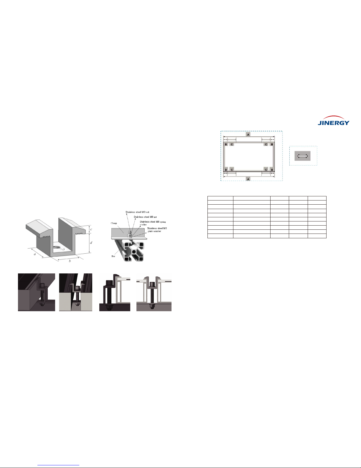
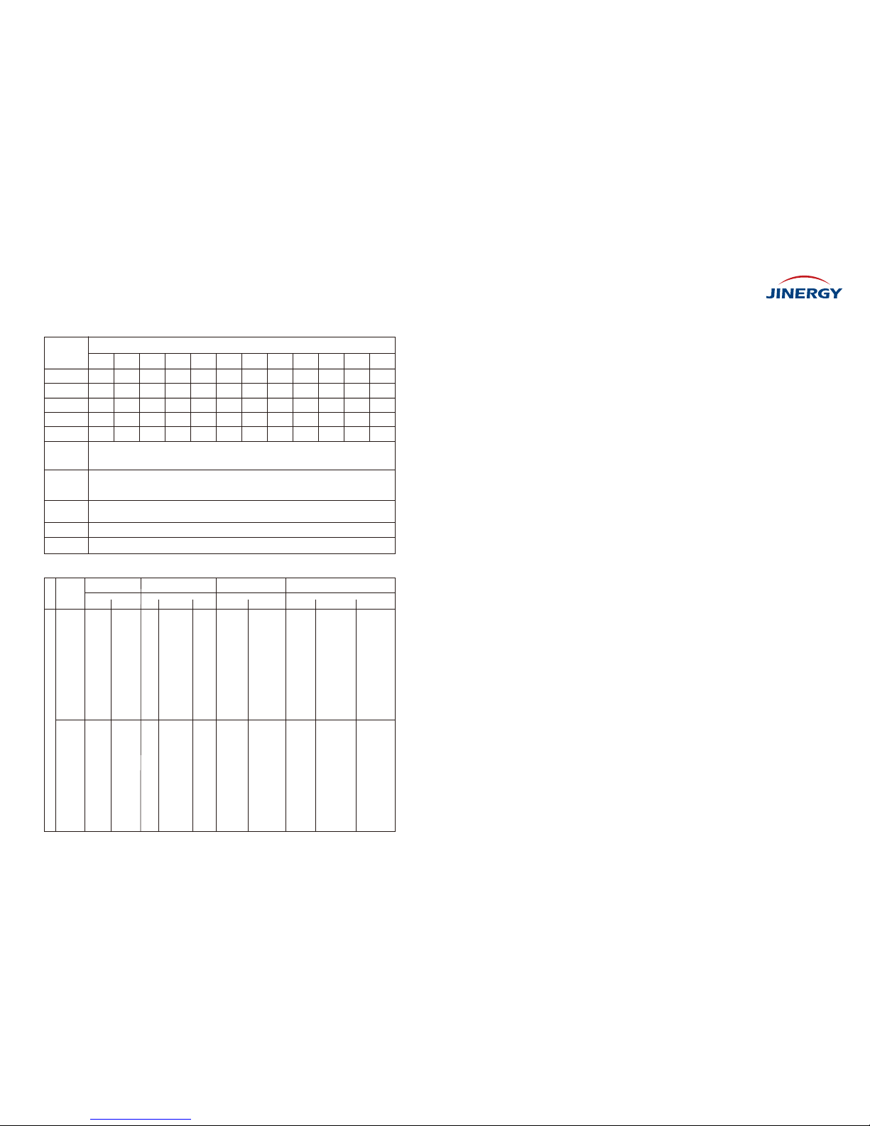
Table 1
3 4

3. Secure each bolt to the frame with 2 stainless-steel washers, one on each side of the mo- unting
structure; and screw on either a stainless-steel spring washer or a toothed lock washer. Finally,
secure with a stainless steel nut (M6 or M8).
4. The torque for tightening the nut and bolts recommended 13Nm when the property class of
bolts and nuts is Class 8.8.
3.2.2 Clamping
Modules can be laid across the supporting bars (Fig. c) .
Remark: Illustrations of the three different methods for clamping modules onto the frame with aluminum clamps.
and maximum series overcurrent protective device in the combiner box are recommended for
reverse current protection when more than three strings are connected in parallel.
2.2.16 The solar modules are recommended to be installed over a fireproof and insulating roof
covering when installed on a roof.
2.2.17 Module may not be contacted during working.
2.2.18 Modules should be safely fixed on the roof to bear all expected loads, including wind and
snow loads.
3. Mechanical Installation
3.1 Installation Condition
3.1.1 Environment temperature: -40 to 85℃
3.1.2 Operating temperature: -40 to 85℃
3.1.3 Mechanical load on panels (e.g., from wind or snow): wind load less than 2400 Pa/snow
load less than 5400 Pa.
3.1.4 Tilt Angle selection: The installation should be facing north in the southern hemisphere and
facing south in the northern hemisphere.
3.1.5 To maintain the modules’ Class C fire rating, the fire class of the roof and building mate-
rials should higher than Class C. The fire rating of this module is valid only when mounted in the
manner specified in the mechanical mounting instructions.
3.1.6 Raise the distance when installation requirement is greater than or equal to 0.3 m. Mod-
ule installation use appropriate installation angle, refer to the following Table 2.
3.1.7 Considering the minimum mechanical means for installing a module securely on a roof.
3.2 Installation Methods
3.2.1 Bolting
All modules must be securely fastened with at least 4 bolts (Fig. a). For maximum security ag-
ainst strong winds or heavy snow falls, suggestion for all of the mounting holes should be used.
Local latitude
0°~15°
15°~25°
25°~30°
30°~35°
35°~40°
>40°
Installation angle
15°
latitude
latitude+5°
latitude+10°
latitude+15°
latitude+20°
Table 2
Fig. a
Fig. c
Fig. b
Module Frame
M6 or M8 Bolt
Washer
Mounting structure
Washer
Spring Washer
M6 or M8 Nut
5 6
Bolts are inserted as described in the process below (Fig. b).
1. Place the module on the supporting bars underneath.
2. Insert stainless-steel bolts (M6 or M8) through the holes (use M6 series mounting access-
ories when the size of mounting holes is 7x11.5mm and use M8 series when the size is 9x13
mm) in the frame according to the Fig. a. For maximum security against strong winds and he-
avy snow, all available mounting holes should be used.
Remark: As for above diagram, the solid red arrows indicate primary bolt positions; dashed green arrows indicate positions where bolts can
be added for additional support.

Fig. f Fig. g
Fig. h
Each aluminum mounting clamp comes with an M8 bolt, a plain washer, a spring washer, and an
M8 nut. To fasten the module:
1. Place the module on the two supporting bars (not provided). The bars should be made with
stainless material or treated with an anti-corrosion process (e.g., anodic oxidation treatment).
2. The bar’s top surface contacted with module frame should come with grooves compatible with
an M8 bolt.
3. If the bars do not come with grooves, holes of a suitable diameter may need to be drilled to
allow bolts to be attached to the bars at the same locations as mentioned before.
4. Secure each clamp by attaching plain washer, spring washer, and nut, in that order.
5. Both of close-ups of Fig. f indicate the middle clamps and Fig. g indicate the side clamps for
your reference. The dimensions for the middle clamps are a ≥ 40mm, b ≥ 26mm, c = 8mm, d ≥
28mm, and Ø = 9mm. The torque for tightening the nut and bolts recommended 28Nm when the
property class of bolts and nuts is Class 8.8.
6. Especially for Fig. c mounting method, slide bolts through groove on the supporting bars next
to the locations where the 4 clamps are to be fastened. The module may be clamped only in
the permitted clamping area as on the long edge of the frame. For exact locations on the frame
refer to Fig. h in conjunction with Table 3 below.
Table 3
End Clamp installation Middle Clamp installation
7 8
For exact dimensions for a given module series, please see the following Table 3. Use in conjunction with Fig. i to determine permitted
clamping locations for a given module series for clamping with clamps.
Variable clamping range
4. Electrical Installation
Details for wiring in accordance with the NEC, and that the grounding method of the frame of
arrays shall comply with the NEC, Article 250. CNL model instruction manuals shall also incl-
ude a statement that installation shall be in accordance with CSA C22.1, Safety Standard for
Electrical Installations, Canadian Electrical Code, Part 1.
4.1 Installation
4.1.1 The electrical characteristics are within ±10 percent of the indicated values of Isc、Voc
and Pmax under standard test conditions (irradiance of 1000mW/cm, AM 1.5 spectrum, and
a cell temperature of 25°C (77°F)).
4.1.2 The maximum system voltage for all module series is 1000V for North American Market
and 1000V for European Market.
4.1.3 Connect quantity of modules that match the voltage specifications of the inverters used
in system. Commended number of 60pcs module is 20 in series and 1 in parallel, 72pcs
module is 17 in series and 1 in parallel. Modules must not be connected together to create a
voltage higher than the permitted maximum system voltage under the worst local temperature
conditions.
4.1.4 Under normal conditions, a photovoltaic module is likely to experience conditions that
produce more current and/or voltage than reported at standard test conditions. The requirem-
2
Module
JNMP60-XXX
JNMP60(5BB)-XXX
JNMM60-XXX
JNMP60-XXX
JNMP60(5BB)-XXX
JNMM60-XXX
JNMP72-XXX
JNMP72(5BB)-XXX
JNMM72-XXX
Series Dimension(mm)
1650*992*35/40
1650*992*35/40
1650*992*35/40
1640*992*35/40
1640*992*35/40
1640*992*35/40
1956*992*35/40/45
1956*992*35/40/45
1956*992*35/40/45
A(mm)
1650
1650
1650
1640
1640
1640
1956
1956
1956
B(mm)
200
200
200
200
200
200
380
380
380
C(mm)
210
210
210
210
210
210
100
100
100

Fig. h
Nut
Gasket
Fixed end
Bolt
Fastening bolt
Frame
Ground wire
5.1 Regularly carry out a visual inspection for dirt, dust, bird dropping, leaves, and other
detritus covering the modules.
5.2 If there is a buildup of dirt or dust on the module surface, wash the module with clean water
and a gentle implement (a sponge). Never use chemicals on the surface of the module.
5.3 If snow is present, a soft-bristled brush with soft bristles may be used to clean the surface
of the modules.
5.4 Regular electrical and mechanical inspection by a licensed professional will keep the
system safe and operating at maximum efficiency.
6. Attachment
6.1 Electricity performance
6.1.1 Electrical specifications of JNMM60-xxx (xxx=235-280) Series 6 inch Mono-crystalline
solar modules
Table 4
9 10
Grounding the aluminum frame with copper wire
ents of the National Electrical Code (NEC) in Article 690 shall be followed to address these
increased outputs. In installations not under the requirements of the NEC, the values of Isc and
Voc marked on this module should be multiplied by a factor of 1.25 when determining coonductor
capacities, over current device ratings, and size of controls connected to the PV output.
4.1.5 Each module (or series-connected string of modules) shall be provided with the maximum
series overcurrent protective device, specified as 15A for the 6 inch cell module series.
4.1.6 Use a special solar cable and plugs for installing the PV system and make sure that all
connections are safe and tight. The cable cross section size should be 4mm (12AWG) and able
to withstand the maximum possible system open-circuit voltage.
4.1.7 Bypass diodes are included in module junction boxes to avoid decreased module perfor-
mance in the event of shade or shelter. Please check the relevant product datasheet for the
specific diodes of J-box.
4.2 Grounding
4.2.1 Use the marked 5.5mm grounding holes (5.5mm) to ground the anodized frame. Use an
M5 nut, an M5 gasket, and an M5 bolt, Fastening bolt and a Ground wire. All nuts, bolts, and
gasket are type M5 and should be made of stainless steel (Fig.h).
4.2.2 Fixed Ground wire on Fixed end through fastening bolt. (Note that the copper wire cannot
be attached directly to the aluminum).
4.2.3 Put the bolt through the Fixed end and then through the hole in the aluminum frame.
4.2.4 Add the gasket and nut on the other side of the bolt and tighten to secure all parts. The
tightening torque should be 2.1±0.1Nm.
5. Maintenance and Disposal
Module Type
Pmax(W)
Vmp(V)
Imp(A)
Voc(V)
Isc(A)
Maximum
System
Voltage(VDC)
Maximum
Series
Fuse(A)
Dimensions
(mm)
STC
Weight(Kg)
1000
15
1650*992*35/40 or 1640*992*35/40
AM=1.5, E=1000W/m², T=25℃
18.6/18.9 or 17.6/17.9
JNMM60-
2
235
235
30.10
7.81
37.25
8.51
240
240
30.20
7.95
37.35
8.63
245
245
30.30
8.09
37.43
8.75
250
250
30.40
8.22
37.51
8.88
255
255
30.50
8.36
37.59
9.03
260
260
30.60
8.50
37.73
9.18
265
265
30.70
8.63
37.91
9.31
270
270
30.80
8.77
38.10
9.45
275
275
30.90
8.90
38.30
9.57
280
280
31.10
9.01
38.52
9.67

11 12
Table 5
Table 6
6.1.2 Electrical specifications of JNMP60-xxx (xxx =240-285) Series 6 inch Polycrystalline solar
modules
6.1.3 Electrical specifications of JNMP60(5BB)-xxx (xxx =240-285) Series 6 inch Polycrystalline
solar modules
6.1.5 Electrical specifications of JNMP72-xxx (xxx =285-340) Series 6 inch Polycrystalline solar
modules
Table 8
6.1.4 Electrical specifications of JNMM72-xxx (xxx =290-340) Series 6 inch Mono-crystalline
solar modules
Table 7
Module Type
Pmax(W)
Vmp(V)
Imp(A)
Voc(V)
Isc(A)
Maximum
System
Voltage(VDC)
Maximum
Series
Fuse(A)
Dimensions
(mm)
STC
Weight(Kg)
1000
15
1956*992*35/40/45
AM=1.5, E=1000W/m², T=25℃
22.4/20.0/22.4
JNMP72-
Module Type
Pmax(W)
Vmp(V)
Imp(A)
Voc(V)
Isc(A)
Maximum
System
Voltage(VDC)
Maximum
Series
Fuse(A)
Dimensions
(mm)
STC
Weight(Kg)
1000
15
1650*992*35/40 or 1640*992*35/40
AM=1.5, E=1000W/m², T=25℃
18.6/18.9 or 17.6/17.9
JNMP60-
240
240
29.67
8.09
37.25
8.48
245
245
29.88
8.20
37.34
8.63
250
250
29.98
8.34
37.41
8.79
255
255
30.25
8.43
37.54
8.94
260
260
30.51
8.52
37.65
9.09
265
265
30.71
8.63
37.81
9.24
270
270
30.80
8.77
38.10
9.45
275
275
31.00
8.88
38.20
9.48
280
280
31.19
8.98
38.34
9.59
285
285
31.41
9.08
38.45
9.73
Module Type
Pmax(W)
Vmp(V)
Imp(A)
Voc(V)
Isc(A)
Maximum
System
Voltage(VDC)
Maximum
Series
Fuse(A)
Dimensions
(mm)
STC
Weight(Kg)
1000
15
1650*992*35/40 or 1640*992*35/40
AM=1.5, E=1000W/m², T=25℃
18.6/18.9 or 17.6/17.9
JNMP60-
240
240
29.34
8.18
36.88
8.77
245
245
29.63
8.27
37.11
8.84
250
250
29.95
8.35
37.33
8.91
255
255
30.26
8.43
37.52
8.98
260
260
30.56
8.51
37.69
9.05
265
265
30.86
8.59
37.89
9.12
270
270
31.15
8.67
38.14
9.20
275
275
31.43
8.75
38.27
9.27
280
280
31.72
8.83
38.47
9.34
285
285
31.99
8.91
38.66
9.41
290
290
36.31
7.98
44.93
8.62
290
295
36.48
8.09
45.01
8.71
290
300
36.60
8.20
45.11
8.81
290
305
36.72
8.31
45.28
8.92
290
310
36.84
8.41
45.49
9.01
290
315
36.96
8.51
45.70
9.10
290
320
37.08
8.62
45.87
9.21
290
325
37.20
8.73
45.97
9.31
290
330
37.32
8.84
46.07
9.41
290
335
37.43
8.95
46.16
9.52
290
340
37.63
9.04
46.30
9.64
Module Type
Pmax(W)
Vmp(V)
Imp(A)
Voc(V)
Isc(A)
Maximum
System
Voltage(VDC)
Maximum
Series
Fuse(A)
Dimensions
(mm)
STC
Weight(Kg)
1000
15
1956*992*35/40/45
AM=1.5, E=1000W/m², T=25℃
22.4/20.0/22.4
JNMP72-
285
285
35.60
8.00
44.51
8.52
290
290
35.86
8.09
44.65
8.64
295
295
35.98
8.20
44.74
8.76
300
300
36.30
8.26
44.82
8.88
305
305
36.61
8.33
44.91
8.99
310
310
36.92
8.40
45.00
9.10
315
315
37.24
8.46
45.08
9.22
320
320
37.36
8.57
45.17
9.34
325
325
37.48
8.67
45.33
9.44
330
330
37.68
8.76
45.47
9.55
335
335
37.88
8.85
45.59
9.67
340
340
38.08
8.93
45.70
9.79

13
NO
1
Model
Type Manuf-
acturer
Manuf-
acturer
Manuf-
acturer
CableDiode
Type
PV1-F
Diam-
eter
4.0mm
Connector
Type
Junction Box
Type Manufacturer Temperature
Rating
-40 to 85℃
2
6.2 List of manufacturers and types of J-box, connector and cable
Table 10
6.1.6 Electrical specifications of JNMP72(5BB)-xxx (xxx =285-340) Series 6 inch Polycrystalline
solar modules
Table 9
Module Type
Pmax(W)
Vmp(V)
Imp(A)
Voc(V)
Isc(A)
Maximum
System
Voltage(VDC)
Maximum
Series
Fuse(A)
Dimensions
(mm)
STC
Weight(Kg)
1000
15
1956*992*35/40/45
AM=1.5, E=1000W/m², T=25℃
22.4/20.0/22.4
JNMP72-
285
285
35.15
8.11
44.34
8.81
290
290
35.41
8.19
44.56
8.86
295
295
35.68
8.27
44.82
8.91
300
300
35.93
8.35
45.01
8.96
305
305
36.19
8.43
45.21
9.01
310
310
36.43
8.51
45.34
9.06
315
315
36.85
8.55
45.57
9.11
320
320
37.13
8.62
45.78
9.16
325
325
37.32
8.71
45.86
9.21
330
330
37.63
8.77
46.01
9.26
335
335
37.88
8.85
46.15
9.31
340
340
38.08
8.93
46.33
9.36
JNMM72-
xxx;
JNMP72-
xxx;
JNMP72
(5BB)-xxx
15SQ045;
20SQ045
Jinan
JingHeng
Electronics
Yangzhou
Yangjie
Electronic
Technology
Co.,Ltd
ZheJiang
ChuangYuan
Photovoltaic
Technology
Co.,Ltd.
Jiangsu Jingke
New Energy
Technology
Co.,Ltd
Suzhou
Baohing
Electric
Wire&Cable
Co., Ltd.
Wuxi
Xinghongye
Wire & Cable
Co. Ltd.
ZheJiang
ChuangYuan
Photovoltaic
Technology
Co.,Ltd.
ZheJiang
ChuangYuan
Photovoltaic
Technology
Co.,Ltd.
Jiangsu
Jingke New
Energy
Technology
Co.,Ltd
PV-CY01L
PV-CY05L
CABLE-JK4
PV-CY1202
JK-BOX018
PV1-F 4.0mm -40 to 85℃
2
JNMM60-
xxx;
JNMP60-
xxx;
JNMP60
(5BB)-xxx
15SQ045;
20SQ045
Jinan
JingHeng
Electronics
Yangzhou
Yangjie
Electronic
Technology
Co.,Ltd
ZheJiang
ChuangYuan
Photovoltaic
Technology
Co.,Ltd.
Jiangsu Jingke
New Energy
Technology
Co.,Ltd
Suzhou
Baohing
Electric
Wire&Cable
Co., Ltd.
Wuxi
Xinghongye
Wire & Cable
Co. Ltd.
ZheJiang
ChuangYuan
Photovoltaic
Technology
Co.,Ltd.
ZheJiang
ChuangYuan
Photovoltaic
Technology
Co.,Ltd.
Jiangsu
Jingke New
Energy
Technology
Co.,Ltd
PV-CY01L
PV-CY05L
CABLE-JK4
PV-CY1202
JK-BOX018
Other manuals for JNMP60 series
2
This manual suits for next models
5
Table of contents
Other Jinergy Solar Panel manuals
Popular Solar Panel manuals by other brands

Sonnenkraft
Sonnenkraft SKR500 Series manual

LG
LG LG240M1C installation instructions

Battery Power Solutions
Battery Power Solutions SunPower SP40 manual

Tycon Power Systems
Tycon Power Systems RPDC-12 Series quick start guide

RM Solar
RM Solar S Class 20 Pro instruction manual

Energizer
Energizer HardCase Sunpack 180W user guide