JMQ E6 User manual

1
JMQ E6
-

2
CONTENTS
Contents ...........................................................................................................1
Safety Instruction .............................................................................................2
Product Overview ............................................................................................3
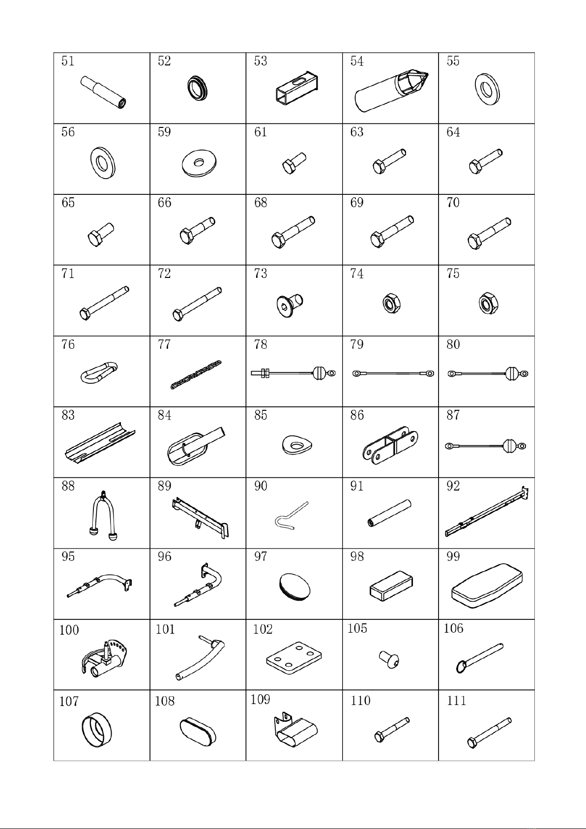
Parts List ..........................................................................................................4-9
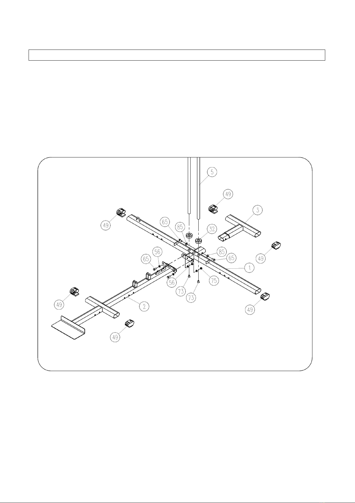
Assembly Instruction ....................................................................................10-28
Daily Care & Maintenance ............................................................................29
Friendly Reminder:
• Product or part pictures here may vary slightly from actual item due to model upgrades.
But they share similar assembly instruction. Please refer this manual as reference. Should you
have any question, please don’t hesitate to contact us for support. Thank you!
• Please check the packing details before assembly, if there is any missing part, contact after-sales
service department for support.
•
Please read all instructions carefully before using the product. Retain this user manual for future
reference.

3
General Assembly Drawing
MLD-M6
Executed Standard: GB17498.1
No.
Name
Qty.
No.
Name
Qty.
*Bench Assembly Instruction is on Page 28.

4
List of parts
1
Main base
1
37
Φ25 handle cover
4
2
Front underframe
1
38
Arm rest
1
3
Rear base
1
39
Back rest
1
4
Front column
1
40
Saddle
1
5
Counterweight guide bar
2
41
Pull knob
2
6
Push arm (right)
1
42
Φ19 bushing
2
7
Winged rack
1
43
Fixing knob of winged rack
1
8
Top beam
1
44
Φ25 foam cover
8
9
Saddle frame
1
45
38x38 square pipe plug
4
10
Front support for saddle
mounting bracket
1
46
25x50 square pipe plug
2
11
Push arm (right)
1
47
40x80 elliptical pipe plug
3
12
48
38x38 square pipe sleeve
2
13
Leg strength arm
1
49
40x80 foot pipe sleeve
6
14
Arm rest support
1
50
Handle (with iron piece)
2
15
Fixing axle of winged rack
1
51
Push arm handle
4
16
Winged rack screw
1
52
Φ50 round pipe plug
1
17
Connector
2
53
50x50 square bushing
1
18
Sandbag draw cord
1
54
Sandbag
1
19
Pulley
16
55
Flat pad Φ8
22
20
Pulley cross U-frame
1
56
Flat pad Φ10
94
21
Pulley single U-frame
2
57
Self drilling screw M4.2x19
1
22
Back pull rod
1
58
20x40 square pipe plug
1
23
Rowing rod
1
59
Large flat pad Φ10
4
24
Adjustment plate
2
60
Flat pad Φ5
1
25
Φ25 foam tube (380mm)
4
61
Hexagon head bolt M8x16
14
26
Counterweight top block
1
62
Tapered cushion
1
27
Counterweight block
12
63
Hexagon head bolt M8x40
1
28
Counterweight spacer
1
64
Hexagon head bolt M8x55
2
29
Weight increasing rod fixing
pin
1
65
Hexagon head bolt M10x25
17
30
Weight increasing rod bushing
1
66
Hexagon head bolt M10x45
16
31
Weight increasing rod
1
67
Rear support frame
1
32
Counterweight cushion
2
68
Hexagon head bolt M10x60
8
33
L-shaped weight increasing pin
1
69
Hexagon head bolt M10x65
2
34
Φ80x160 foam
8
70
Hexagon head bolt M10x70
1
35
Φ90x245 foam
2
71
Hexagon head bolt M10x100
11
36
Pull pin
4
72
Hexagon head bolt M10x110
2
No.
Name
Qty.
No.
Name
Qty.

5
73
Countersunk head hexagon
socket bolt M10x20
2
109
Pedal support
1
74
Anti-lock nut M8
1
110
Hexagon head bolt M8x65
4
75
Anti-lock nut M10
53
111
Hexagon head bolt M8x95
2
76
Buckle
7
112
Anti-lock nut M12
3
77
Iron chain (280mm)
2
113
Curved spacer Φ8
6
78
Back pull rod cord (2,650mm)
1
114
M10x55 square well bolts
2
79
Butterfly arm pull cord
(2,900mm)
1
115
Saddle mounting bracket
1
80
Rowing rod pull cord
(2,770mm)
1
116
Left column pipe
1
81
Sit-up bench rear bottom pipe
1
117
Left connecting bend
1
82
Back rest frame
1
83
Steel plate cover
1
119
40x80 elliptical bushing
1
84
leg wrapping bands
1
120
Iron chain (490mm)
1
85
Curved spacer Φ10
13
121
Flat pad Φ12
4
86
Pulley H-shaped U-frame
1
122
Single rod bend
1
87
Abdominal muscle band cord
(2,040mm)
1
123
Single rod frame
1
88
Abdominal muscle band
1
124
Hexagon head bolt M10x55
2
89
Rear top beam
1
125
Hexagon head bolt M12x70
1
90
Sandbag hook
1
126
Welding plate 8
1
91
Φ25 handle pipe
2
127
Hexagon head bolt M10x95
1
92
Right column
1
128
Φ25 tapered pipe plug
1
95
VKR arm (right)
1
96
VKR arm (left)
1
97
Ø60 round pipe plug
4
98
VKR arm cushion
2
99
VKR Back rest
1
100
Push arm attachment (left)
1
101
Push arm (left)
1
102
VKR Connector
1
103
104
105
Bevel head hexagon head bolt
M8x12
4
106
Ring bolt Φ10x70
1
107
Φ50xΦ26 pipe sleeve
2

6
108
40x100 elliptical flat pipe plug
2

7

8

9

10
Installation steps
Notes:
1. Spacers should be placed on both ends of the bolt (against the bolt head and nut), unless otherwise
specified.
2. For preliminary assembly, hand-tighten all bolts and nuts, and tighten with a wrench when fully
assembled.
3. Some parts have been pre-assembled in the factory.
4. The product is recommended to be installed by more than two people.
Figure 1
1. Main base (#1), on front base (#2), rear base (#3), inserted feet bushing (#49);
2. Insert the 2 counterweight guide rods (#5) into the mounting holes of the main base (#2) with
the 3 large holes in the main base (#1) facing upwards and secure with 2 countersunk hex bolts
M10x20 (#73);
3. Insert the rear base (#3) into the main base (#1) and lock with 2 hex head bolts M10x25 (#65)
and 2 curved spacer Φ10 (#85) to lock it firmly;

11
4. Lock the main base (#1) and front frame (#2) together with 2 hex head bolts M10x25 (#65), 4
flat washers Φ10 (#56) and 2 lock nuts M10 (#75);
5. Attach two counterweight cushions (#32) to each of the two counterweight guide rods (#5) as
shown in the figur;
Installation steps
Figure 2
1. Place counterweight block (#27) into counterweight guide bar (#5) in sequence (groove side
down); attach weight increasing rod bushing (#30) to weight increasing rod (#31), align hole in
weight increasing rod bushing (#30) with topmost hole in weight increasing rod (#31), insert
weight increasing rod retaining pin (#29); then insert the weight increasing rod (#31) into the
middle hole of the counterweight block (#27) and align the hole of the weight increasing rod
(#31) with the groove below the counterweight block (#27).
2. Attach counterweight top block (#26) to counterweight guide bar (#5) and weight increasing rod
(#31), place counterweight block spacer (#28) on top of counterweight block top block (#26) and
insert L-shaped weight increasing pin (#33) into weight increasing rod (#31).
3. Attach pulley single U-frame (#21) to left/right U-frame on front column (#4) with 2 M10x65 hex
head bolts (#69), 4 flat pad Φ10 (#56) and 2 lock nuts M10 (#75); attach the 38x38 square pipe
plug (#45) to the front riser (#4) as shown and sleeve the 38x38 square pipe.
4. Installed to the front bottom frame (#1) with 3 hex head bolts M10x100 (#71, 4 flat washers

12
Φ10 (#56) and 2 lock nuts M10 (#75);
5. Place the top beam (#8) in the position shown in the figure, put the connecting piece (#17) and fix
it with 2 hex head bolts M10x60 (#68), 2 lock nuts M10 (#75) and 4 flat washers Φ10 (#56);
Connect and secure the top beam (#8), rear top beam (#89) and counterweight guide bar (#5)
with 2 hex head bolts M10x25 (#65) and 2 flat pad Φ10 (#56); attach the 40x80 elliptical pipe
plug (#47) to the top beam (#8).
Installation steps
Figure 3
1. Install 40x80 oval pipe plug (#47) into left connection bend (#117) as shown in the figure;
attach a sandbag hook (#90) to the left connection bend (#117) with a curved spacer Φ10 (#85)
and a locknut M10 (#75).
2. Install the left column (#116) on the main base (#1) with 3 hex head bolts M10x100 (#71, 6
flat washers Φ10 (#56) and 3 lock nuts M10 (#75);
3. Insert a left connection bend (#117) at the upper end of the left column (#116) into the rear top
beam (#89) connection with 2 hex head bolts M10x60 (#68), 4 flat pad Φ10 (#56) and 2 lock
nuts M10 (#75);
4. Attach the back cushion (#39) to the front column (#4) with 2 hex head bolts M8x55 (#64) and 2
flat pads Φ8 (#55).

13
5. Attach the winged rack screw (#16) to the U-frame of the front column (#4) square tube with 1
hex head bolt M8x40 (#63), 2 flat pad Φ8 (#55) and 1 locknut M8 (#74); screw the winged rack
fixing knob (#43) to the winged rack screw (#16).
6. Cover a 25X50 square pipe plug (#46) at the end of the winged rack (#7).
7. Attach the Φ19 liner to the top beam (#8) as shown, and mount the winged rack (#7) to the top
beam (#8) via the winged rack fixing axle (#15); then lock 2 hex head bolts M10x25 (#65) and 2
large flat pads Φ10 (#59) to both ends of the winged rack fixing axle (#15).
Installation steps
Figure 4
1. Installed on the main base (#1) with 3 hex head bolts M10x100 (#71), 6 flat pad Φ10 (#56) and
3 locknut M10 (#75), with bolts temporarily left untightened.
2. Lock the bar frame (#123) to the single rod bend tube (#122) with 2 hex head bolts M10x55

14
(#124), 4 flat washers Φ10 (#56), 2 locknut M10 (#75) and 1 hex head bolt M10x95 (#127), 2
curved washers Φ10 (#85) and 1 locknut M10 (#75).
3. Insert a single rod bend (#122) at the upper end of the right column (#92) into the rear top beam
(#89) connection with 2 hex head bolts M10x110 (#72), 4 curved pad Φ10 (#85) and 2 lock nuts
M10 (#75) to connect the welded plate 8 (#126), rear top beam (#89) and right column (#92);
4. Lock all bolts.
Installation steps
Figure 5
1. Install the Φ60 plastic pipe plug (#97) on the right side of the push arm (#11) as shown; then
place the foam Ø53ר90×245 (#35) on the right side of the push arm (#11).
2. Insert a shaft-mounted Ø19 bushing (#42) on the upper right (#11) of the push arm into the
winged rack (#7) as shown; lock with a flat pad Ø12 (#121) and a locknut M12 (#112); (left

15
assembled with the same methods).
3. Attach the push arm handle (#51) to the push arm (right) (#11) with 1 hexagonal bolt M10×25
(#65) and 1 arc pad Ø10 (#85); then lock the long pull handle (with iron piece) (#50) to the
other end of the push arm handle (#51) with 1 hexagonal bolt M10×25 (#65) and 1 large flat pad
Ø10 (#59).
4. Assemble the left part in the same manner.
Installation steps
Figure 6
1. Install 50x50 square bushings (#53) into cushion mounting rack (#115).
2. Attach the saddle mounting rack (#115) and connecting piece (#17) to the front column (#4)
with 2 hex head bolts M10x60 (#68), 4 flat washers Φ10 (#56) and 2 lock nuts M10 (#75).
3. Attach a 40x80 elliptical bushing (#119) to saddle mount front support (#10); then attach 38x38
square pipe plug (#45) to saddle mount front support (#10) and sleeve 38x38 square pipe;
4. Connect the front support of the saddle mount (#10) to the saddle mount (#115) with 2 M10x55
square well bolts (#114), 2 flat pads Φ10 (#56) and 2 lock nuts M10 (#75).
5. Then attach the front support (#10) to the front bottom support (#2) with 2 hex head bolts

16
M10x100 (#71, 4 flat washers Φ10 (#56) and 2 lock nuts M10 (#75);
6. Insert Φ50 round pipe plug (#52) into leg force arm (#13);
7. Attach the leg force arm (#13) to the front support of the saddle mount (#10) with 1 hex head
bolts M10x70 (#70, 2 flat washers Φ10 (#56) and 1 lock nuts M10 (#75);

17
Installation steps
Figure 7
1. Attach the arm force pad (#38) to the arm force pad frame (#14) with 4 hex head bolts M8x16
(#61) and 4 flat pads Φ8 (#55);
2. Insert the assembled arm cushion frame (#14) partially into the front support (#10) of the
cushion mounting rack and lock the pull knob (#41);
3. Attach 38x38 square pipe plug (#45) to cushion holder (#9) as shown;
4. Mount the cushion (#40) to the cushion frame (#9) with 4 hex head bolts M8x16 (#61) and 4 flat
pads Φ8 (#55);
5. Insert the assembled cushion frame (#9) partially into the cushion mounting rack (#115) and
lock the pull knob (#41);

18
Installation steps
Figure 8
1. Insert 2 Φ25 foam pipes (380mm) (#25) into the leg force arm (#13) and the front support of the
saddle mount (#10) respectively;
2. Then insert Φ80x160 foam (#34) at both ends of Φ25 foam pipe (380mm) (#25);
3. Finally, insert the Φ25 foam cover (#44) at both ends of the Φ25 foam pipe (380mm) (#25).

19
Installation steps
Figure 9
1. Install 2 Φ50xΦ26 sleeves (#107) and 2Φ25 handle sleeves (#37) on right/left VKR arms
(#95/#96) respectively;
2. Secure the right/left VKR arm (95#/96#) to the front column (#92) with 1 hex head bolt M12x70
(#125), 2 flat washers Φ12 (#121) and 1 locknut M12 (#112);
3. Install the 2 handle Φ25x120 (#37) to one end of the Φ25 handle pipe (#91) without the weld
nut.
4. Install Φ25 handle pipe (#91) on right/left VKR arm (#95)/(#96) with 2 hex head bolts M10x25
(#65) and 4 curved pads Φ10 (#85).
5. Install 2 VKR arm pads (#98) with 4 hex head bolts M8x65 (#110) and 4 curved pads Φ8
(#113).
6. Install the VKR arm connector (#102) on the right/left VKR arm (#95/#96) with four bevel head
hex bolts M8x12 (#105) and four flat pads Φ8 (#55).
7. Insert the ring pins Φ10x70 (#106) into the front column #92).

20
Installation steps
Retractable
Figure 10
As shown, the VKR arm can be folded over when not in use and the pin (#106) removed and
inserted into the hole under the front column (#92) to prevent the VKR arm from being folded down.
Installation steps
This manual suits for next models
1