Jntech JNPH3AR-S User manual

Power Pack
User Manual
JNPH3AR-S
JNPH3AR-S -EN-V1.4

The copyright belong to Hefei JNTECH New Energy Co., Ltd.
This document involves the proprietary and confidential information about
Solar pump system Power Pack of Hefei JNTECH New Energy Co. Ltd. It
strictly prohibited to disclose the document by duplicating, photocopying,
publishing online and in other forms without Hefei JNTECH’s permission.
Hefei JNTECH New Energy Co., Ltd. reserves the right to change details in
this publication without notice.
V1.4

I
Preface
Manual Instruction
This manual describes the transportation, installation, operation, maintenance
and troubleshooting of the following JNTECH Power Pack (Short as Power
Pack).
●JNPH3AR-S
For JNP37KH solar pumping system.
Target Reader
This manual applies to the professional engineering and technical person who
is responsible for installing and operating of Power Pack.
Use the Manual
Please read this manual carefully before installing and operating Power Pack.
Please keep this manual well for operation and maintenance in future.
The manual content would be constantly updated and revised, but it
unavoidably has slightly discrepancies or errors with real Power Pack, please
kind prevails if user purchases our Power Pack.
Symbol Used
The following safety symbols may be used in this manual, and the
meanings are shown in below.
Safety Symbol
Meaning
Danger
Means that it may lead to serious accident of injuries, if
safety warning is ignored.
Warning
Means that it may lead to serious accident of injuries,
equipment serious damage or main business interruption, if
safety warning is ignored.
Notice
Means that it may lead to moderate accident of injuries,
equipment moderate damage or part of the business
interruption, if safety warning is ignored.
Noted
Means that the content is additional information.
Power Pack related symbols:
Symbol
Meaning
DC power.
AC power.

II
Refer to relevant instructions.
Cannot discard Power Pack together with domestic garbage.
Beware of dangerous high-voltage.
Should wait for 5 minutes after Power Pack and PV panel
or AC power are disconnected, then Power Pack only can
be touched.
Beware of hot surface
The Power Pack temperature can exceed 60℃during operation.
CE certificates

III
Contents
Preface.............................................................................................. I
Manual Instruction ..................................................................... I
Target Reader............................................................................. I
Use the Manual........................................................................... I
Symbol Used .............................................................................. I
1 Safety Instructions.................................................................... 1
2 Product Introduction................................................................. 4
2.1 Power Pack application system Introduction ..................... 4
2.2 Product’s Introduction ........................................................ 5
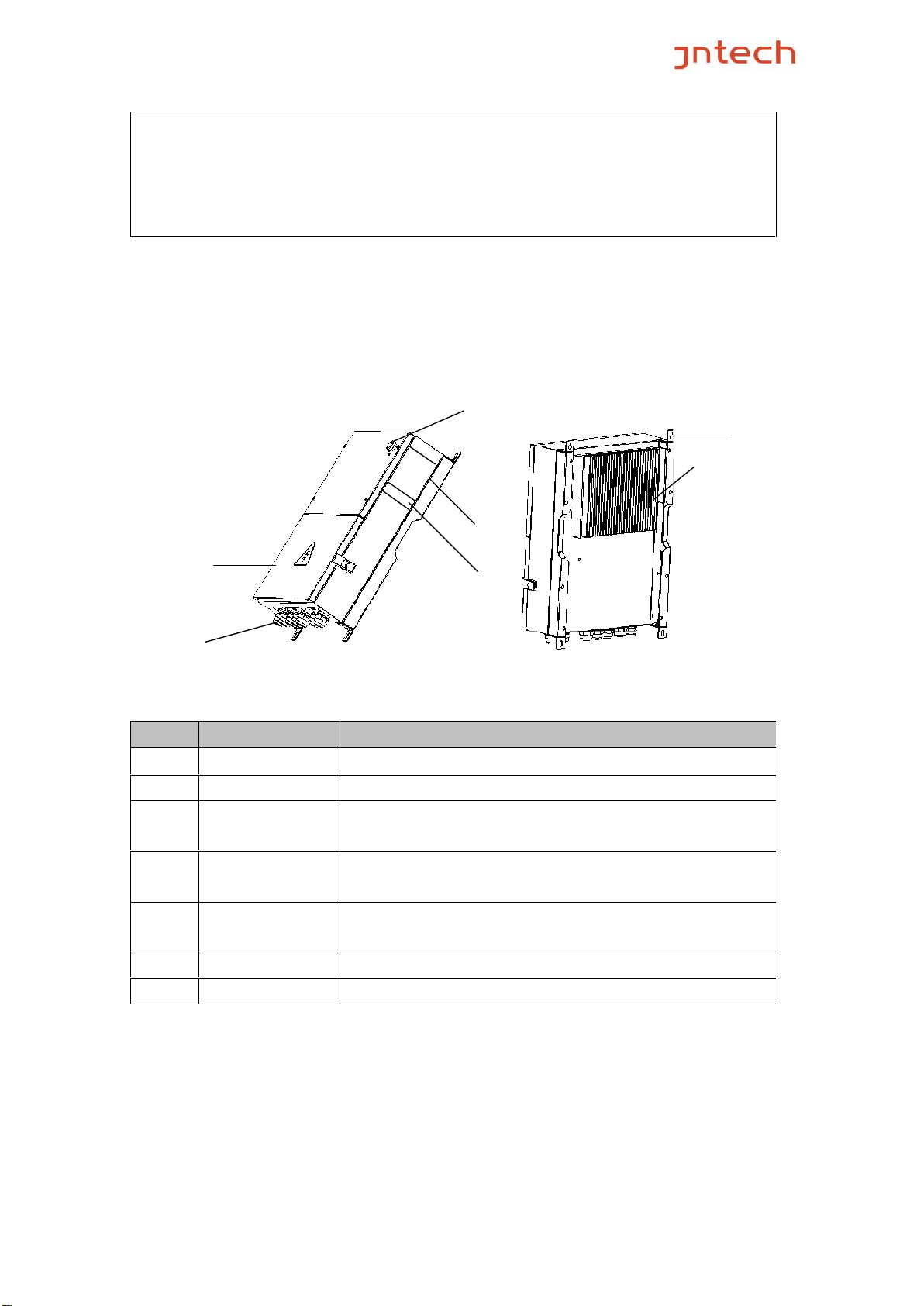
2.2.1 Appearance.................................................................. 5
2.2.2 Production Dimensions............................................... 6
2.2.3 Product Name.............................................................. 6
3 Power Pack Unpacking ............................................................. 7
3.1 Unpacking Check ................................................................ 7
3.2 Identify Power Pack............................................................. 8
4 Installation procedure............................................................... 9
4.1 Prepare Installation Tools ................................................... 9
4.2 Installation Site Required...................................................10
4.3 Installation Direction..........................................................10
4.4 Installation of Power Pack..................................................12
5 Electrical Connection...............................................................13
5.1 Power Pack Connecting Terminals.....................................13
5.2 Cable Selection ..................................................................16
5.3 Connector Disassembling ..................................................16
6 Power Pack Commissioning ....................................................17
6.1 Inspection before Commissioning .....................................17
6.2 First Commissioning of Power Pack ..................................19
7 Common troubleshooting and maintenance............................22
7.1 Troubleshooting .................................................................22
7.2 Maintenance .......................................................................23
7.3 Contact Customer Service .................................................23
8 Appendix..................................................................................24

1
1 Safety Instructions
For the electrical and electronics equipment, safety relates to the whole
process of installation, commissioning, operation and maintenance. Therefore,
incorrect use or operation would damage the life and personal security of
operating person or the third party, and Power Pack.
In order to reduce damage of Power Pack and other equipment, user or
operating person should strictly abide by all the safety information tips of
danger, warning and notice which are in the process of operating and
maintaining.
Warning!
All the installation and operation of JNPH3AR-S Series Power Pack must
be done by professional and technical person. Professional and technical
person need:
●Receive special training.
●Read this manual carefully and master the operation related to safety
matters.
Any damage caused by improper installation or operation will be beyond
the warranty scope.
Before installation
Notice!
User should check the Power Pack if there is any damage during
transportation. Please contact Hefei JNTECH New Energy Co., Ltd or
transportation company immediately if some problems of Power Pack are
found.
Installing
Ensure Power Pack not have electrical connections and electricity before
installing.
Danger!
The solar cell arrays should be covered with opaque materials when
installing the photovoltaic arrays during the day, otherwise the solar cell
arrays will generate high voltage, causing person casualties.
Waning!
If Power Pack damage caused by the following circumstances will be
beyond the warranty scope.
●Ensure that the open circuit voltage (Voc) of every PV module string do

2
not exceed 880V
●It would influence the machine performance and may cause machine
damage if the installation environment is selected improperly.
●Do not install the Power Pack in inflammable, explosive place or
inflammable, explosive materials storage place.
●Do not install the Power Pack in explosive dangerous place.
●Do not install the Power Pack in place where is vulnerable to lightning
strike.
●Do not install the Power Pack in place where have much salt fog.
●When running the Power Pack, please ensure good ventilation.
●Power Pack should be installed erectly, and ensure the heat sink is
without shelter.
Electrical connections
Warning!
●All the operation and wiring work should be operated by professional
electrical or machine engineer.
●Please do not close any breakers before all the equipment are not fully
connected well.
Notice!
●All the electrical installation must meet the electrical installation standard
of local and country.
●In order to ensure safe running, proper grounding, using appropriate
conductor size and providing short circuit protection are required.
●Connection cable must select suitable specification, firm connection and
good insulation.
Running
Danger!
●Please do not plug any connectors under Power Pack charged state!
●Please do not open the cover plate under Power Pack charged state!

3
Maintenance
Danger!
●Maintenance should be done by professional maintenance technical
person.
●Please ensure that AC side breakers should be turned off firstly, then DC
side breakers should be turned off before checking and maintaining,
after waiting at least 5 minutes, should measure DC side and AC side
voltage with a voltage meter, to ensure that operation under the
circumstance of no voltage between DC side and AC side.

4
2Product Introduction
2.1 Power Pack application system Introduction
The application of Power Pack can keep water pumping system working 24
hours a day. As Utility grid or Generator shall worked as power supplement in
system, besides of solar energy, which produce a great flow rate than you will
see with only solar power. A common application is for diesel generator or
unstable regions of utility grid. When the sun irradiation is insufficient, just
switch on the AC power source, which will work as supplement; And even at
night, AC power source can work as pass by.
Warning!
Power Pack can’t be connected with the PV array, which is positive or
negative grounded!
Figure2-1 Power Pack application System
Noted!
Make sure that Vmp is very near to the rectifier voltage when the
system was designed. That means if the AC voltage is 380V,then the

5
rectifier voltage is 1.414*380V≈537.3V,and the system was designed
used 18 pieces panels which is 30V(Vmp),so Vmp is 30*18=540V.if
the rectifier voltage is more different from Vmp , the power of solar
will not be used in maximum mode.
2.2 Product’s Introduction
2.2.1 Appearance
Figure 2-2 Appearance of Power Pack
Table 2-1 Power Pack appearance information table
No.
Name
Introductions
1
Power Indicator
Light on when Power Pack AC side power on.
2
Bottom Cover
To switch the connect and disconnect PV input.
3
Connection
Terminals
PV Input, AC Input, DC Output.
4
Machine serial
No.
Manufacturing code, when need after-sales service
should provide the No.
5
Nameplate
Power Pack basic parameters listed on the nameplate
for basic information about Power Pack.
6
Radiator
Help machine heat dissipation.
7
Hanger
Help to install and fix Power Pack.
1
2
3
4
5
6
7

6
2.2.2 Production Dimensions
Figure 2-3 Dimension drawing of Power Pack (Unit:mm)
Table 2-3 Power Pack dimension table
Model
Width (mm)
Height(mm)
Depth(mm)
Net weight(kg)
JNPH3AR-S
440
580
240
20
2.2.3 Product Name
The way of product naming, take JNPH3AR-S for example
JN
P
H
3
AR
-
Company name
System name
Functional unit of system
Power level
Used for 30kw to 37kw H series
7
-S
Optimization upgrading

7
3 Power Pack Unpacking
3.1 Unpacking Check
The product has been tested and checked carefully before
transportation, but damage may be caused during transportation,
therefore, the product should also be checked carefully before
installation
●Please check whether Power Pack outer packing is in good condition;
●After unpacking, please check whether the equipment is in good condition;
●According to the packing list to check whether all the parts is correct and in
good condition
If any damage is found, please contact Hefei JNTECH New Energy Co.,
Ltd. or the transportation company. Please keep well the photos taken at
the damaged parts and we’ll provide you with best and fastest services.
Hefei JNTECH New Energy Co., Ltd. supplies the standard Power Pack
and some commonly used accessories as below:
Figure 3-1 Power Pack and standard fittings
Noted!
Photos are for reference only, please in kind prevail!
Table 3-1 Power Pack and fittings table
No.
Introduction
1
Power Pack
Included
2
Expansion bolt
Included
3
Cool pressure terminal
Included
123
4 5 6

8
4
Packing list
Included
5
Quick installation guideline
Included
6
Certificate of inspection
Included
3.2 Identify Power Pack
The nameplate in the side of Power Pack, and it shows the Power Pack
model, some important parameter and certificate mark.
Figure 3-2 Power Pack nameplate
Table3-2 Nameplate information table
No.
Description
1
JNTECH Logo and name.
2
Power Pack model and parameter information.
3
Company and website.
4
Manufacturing code.

9
4Installation procedure
4.1 Prepare Installation Tools
The following tools will be needed during Power Pack installation and
wire connection. You also can choose the right tools according to your
own experience.
Table 4-1 Installation tools list
Sketch map
Name
Recommend
Specification
Function
Wire
crimpers
M2.5-M8
Used for cool pressure
terminal pressure welding
Electric drill
Ф8
Used for Power Pack
installation plate fixed hole
drilling
Straight
screwdriver
Ф5
Used for the PV and AC
input wire installation
Open-end
wrench
No. 10
Used for locking expansion
bolt
示意图
名称
推荐规格
功能
Wire crimpers
M2.5-M8
Used for cool pressure
terminal pressure welding
Electric drill
Ф8
Used for Power Pack
installation plate fixed hole
drilling
Straight
screwdriver
Ф8
Used for the PV and AC
input wire installation
adjustable
wrench
NO. 10
Used for locking expansion
bolt
straight
screwdriver
NO. 10
Used for cable connecting of AC
output side and PV input side
wire stripping
pliers
M1.5~M8
Used for making cable making
percussion
drilling
Φ8
Used for drill hole and hang the
machine

10
internal
hexagonal
wrench
3.5mm
Used for cable connecting of AC
input side
4.2 Installation Site Required
Power Pack installation site environment has very important influence to
the safe operation, the performance and life of the Power Pack. Choose
the right installation site before install the Power Pack.
●All installation must comply with local standards.
●Do not install the Power Pack at a flammable or explosive place or a place
where the flammable or explosive materials are stored.
●Do not install the Power Pack in a place where there is a risk of explosion.
●Do not install the Power Pack in places where the Power Pack is
vulnerable to lightning strike.
●Do not install the Power Pack in a higher salt spray environment.
●Power Pack installation site must be in good ventilation, do not install the
Power Pack in the closed case.
●Power Pack protection level is IP65, can be installed outdoor, when
the Power Pack is installed outdoor, should be installed as far as
possible in the eaves or other have the shadow place, avoiding
direct sunlight, rain and snow.
●Power Pack is installed indoor; keep away from windows, avoiding
lightning.
●The installation place selected should be solid enough to support the
Power Pack weight for a long period.
●The site for Power Pack installation must be clean and the ambient
temperature must be maintained within -25 to +60 °C.
●Power Pack installation site relative humidity should not be more
than 95%, water vapor may corrode Power Pack, and damage the
internal components.
●The Power Pack must be installed in a place convenient for
observation and maintenance.
4.3 Installation Direction
●The Power Pack should be installed vertically or titled backwards with a

11
maximum angle of 10°.
●Do not install Power Pack tilted forwards.
●Never install the Power Pack horizontally.
Figure4-1 Installation directions
●Do not install the Power Pack in a place where children can touch.
●The Power Pack uses air cooling mode and the installation site
selected should ensure the minimum installation spacing between
the Power Pack and the fixed object and the nearby inverters to
ensure good ventilation.
100cm
100cm
100cm
100cm
100cm
100cm
Figure 4-2 Minimum spacing of adjacent installations
Table 4-1 Minimum spacing dimension
Direction
Minimum spacing
Above
100cm
Below
100cm
Sides
100cm
Front
100cm
√
√
Min 80。
×

12
4.4 Installation of Power Pack
Step 1: Fix four hangers to the four corners of Power Pack, shown as
sketch map as below after fastening.
Figure 4-3 Power Pack hangers sketch map
Step 2: Drill holes in the selected installation position according to the
size and shape of installation bracket; suggest drill Diameter
10+1/0, depth 60+5/-0.
Figure 4-4 JNPH3AR-S Installation hole position figure
Step 3: Hang the Power Pack four hangers to the fixed expansion bolt,
tighten bolt with wrench.
Through expansion
bolt to fix the bracket
to the wall
Hangers on the top of
PowerPack
Hangers at the bottom
of PowerPack

5 Electrical Connection
After the mechanical installation of Power Pack being finished, the
electrical connection can be carried out. Following are the operation
rules that need to be followed.
Warning!
●All the electrical connection must meet local electrical connection
standard.
●Only qualified electrical personnel can perform the wiring installation
work.
●Incorrect wiring operation may cause operating casualties or equipment
damage
permanently.
●Ensure that there is no electricity in Output and Input side before the
electrical
connection.
●Grounding correctly, using proper conductor and taking necessary
short-circuit protection to ensure the safe operation of the Power Pack.
●Do not close any circuit breaker before all the electrical connections
being finished.
5.1 Power Pack Connecting Terminals
The input and output terminals are at the bottom of the Power Pack,
including PV INPUT terminals, AC INPUT terminals, and DC OUTPUT
terminals, as shown in the following diagram.
Figure 5-1 External connection terminals of the Power Pack
Table 5-1 Description
Terminals
Description
PV INPUT
PV array input terminals.
AC INPUT
AC power input terminals.
DC OUTPUT
DC output terminal; connect with the input side of solar
pumping inverter.
To solar panel
To 3 phases AC power
To pumping inverter

1.PV INPUT terminals connection
Open the cover through the lock catch on right bottom of Power Pack.
PV connecting terminals are waterproof. Put the cable through terminal
block, and crimp the end into cold-pressed terminals, then finish the
connection in accordance with the PV+ and the PV-.
Operation Instruction
Operation Demonstration
1.Loosen the waterproof
terminal cap, rotate the nut in
counterclockwise to remove
the terminal caps
.
2.Put cable through the
waterproof terminal block, and
then crimp the end into
cold-pressed terminals.
3. Connect the cold-pressed
terminals correctly according
to the "PV+" and "PV-" which
are marked on the terminal
board
In accordance with the above steps, fixing the positive and negative
terminals of PV arrays onto the Power Pack’s input terminal one by one.
PV+ PV-

Noted!
PV+ waterproof terminals are on top of the panel, while the lower are
PV-.
Warning!
Before connecting the PV array to the Power Pack, ensure its earth
impedance is not less than 1Mohm.
Warning!
The positive and negative polarities of PV arrays cannot be inversely
connected to Power Pack.
2.AC INPUT terminals connection
AC INPUT terminals adopt M25 waterproof terminals. The operation
method is the same as terminal disassembling method of the DC INPUT
side. Putting AC input cable through the waterproof terminals block, then
accessing three-phase AC input and grounding wire in accordance with
the "U, V, W, PE" logo.
Figure 5-2: Power Pack’s AC input wiring diagram
3.DC Output terminals connection
Refer to DC input terminals connection.
AC INPUT
terminal Blocks
Table of contents
Popular Power Pack manuals by other brands

Toro
Toro ProPass 200 installation instructions

Makita
Makita PDC01Z instruction manual

Newcastle Systems
Newcastle Systems PowerPack Ultra 2.6 Assembly instructions

e-bike vision
e-bike vision PowerPack Series Manual/Safety Notes

Broncolor
Broncolor Scoro A2 operating instructions

Husqvarna
Husqvarna PP 325 E Operator's manual