Jobsite CT0567 User manual

1
6HP DIESEL REVERSIBLE PLATE COMPACTOR
CT0567
INSTRUCTION MANUAL
IMPORTANT:
These instructions accompanying the product are the original instructions. This document is
part of the product, keep it for the life of the product passing it on to any subsequent holder of
the product. Read all these instructions before assembling, operating or maintaining this
product.
Cannon Tools Limited
Address: 20 Station Road, Rowley Regis, West Midlands, B65 0JU.U.K.

2
EC DECLARATION OF CONFORMITY
We CANNON TOOLS LTD
20 Station road, Rowley Regis, West Midlands,B65 0JU.U.K.
Declare that the following machine complies with the appropriate basic safety
and health requirements of the EC Directive based on its design and type, as
brought into circulation by us.
In case of alteration of the machine, not agreed upon by us, this declaration will
lose its validity.
Product description: 6HP DIESEL REVERSIBLE PLATE COMPACTOR
Model: CT0567
Applicable EC Directives:
EC Machinery Directive 2006/42/EC
Harmonized standards
EN ISO 12100:2010, EN 500-1:2006+A1:2009, EN 500-4:2011
20 Station Road, Rowley Regis, West Midlands, B65 0JU.U.K.
Mr. Gurcharan Tony Singh Sanghera
Managing Director
CANNON TOOLS LTD
2020-11-04

3
1. SPECIFICATION
Power: 6Hp (4.4KW)
Operation Mass: 168kg
Frequency: 4000vpm
Centrifugal Force: 30.5kn
Compaction Depth: 500mm
Travel Speed: 25cm/s
Efficiency: 570 m
2
/hr
Plate Size: 730 X 500mm(includes Extension Plate)
Governed speed: 3200r/min
Engine type:KAMA 178, 4 stroke diesel engine
Sound specification
Measured sound Power level : 105dB(A)
Guaranteed sound power level :108dB(A)
Uncertainty:3dB(A)
Plate ram full load operation noise:
Sound pressure level: 84dB(A)
Sound power level: 97 dB(A)
Vibration specification: 5m
2
/s
APPLICATIONS:
Trench compaction, Earthworks, Road maintenance, Landscaping,
Brick paving, Driveway topping.
2. IMPORTANT SAFETY INFORMATION
Workers who have been trained can operate the machine.
Before using this equipment, study the entire owner’s manual to become
familiar with its operation. Do not allow untrained or unauthorized personnel,
especially children, to operate this equipment. Use only factory authorized
parts for service.
General safety instruction for the operation of power equipment The goal of
our company is to produce power equipment that helps the operator work
safely and efficiently. The most important safety device for this or any tool is
the operator. Care and good judgement are the best protection against injury.

4
All possible hazards cannot be covered here, but we have tried to highlight
some of the important items, individuals should look for and obey caution,
warning and danger signs placed on equipment, and displayed in the
workplace. Operators should read and follow safety instruction packed with
each product. Learn how each machine works. Even if you have previously
used similar machines, carefully check out each machine before you use it.
Get the “feel” of it and know it’s capabilities, limitations, potential hazards,
how it operates, and how it stops.
Hazards And Risks
●
NEVER allow any person to operate the machine without adequate
instruction.
●
ENSURE all operators read, understand and follow the operating
instructions.
●
SERIOUS INJURY could result from improper or careless use of this
machine.
●
Plate compactors are heavy units and should be positioned by two people
of appropriate strength. Using the lifting handles provided on the machine,
along with correct lifting techniques.
Mechanical Hazards
●
DO NOT operate the machine unless all protective guards are in place.
KEEP handles and feet clear of rotating and moving parts as they will
cause injury if contacted.
●
ENSURE that the motor operation switch is in the OFF position and the
spark plug ignition lead is disconnected before removing the guards or
making adjustments.
●
ENSURE both the machine and the operator are stable by setting up on
level terrain and the machine will not tip over, slide of fall while in
operation or unattended.
●
DO NOT leave the machine in operation while it is unattended.
●
ENSURE that the walls of a trench are stable and will not collapse due to
the action of the vibration, prior to commencing compaction.
●
ENSURE that the area to be compacted does not contain any “live”
electrical cables, gas, water or communication services which may be
damaged by the action of vibration.
●
EXERCISE CARE when operating unit. Exposure to vibration or

5
repetitive work actions may be harmful to hands and arms.
●
NEVER stand on the unit while it is operating.
●
DO NOT increase the governed no-load motor speed above 3200 r/min
●
Any increase may result in personal injury and damage to the machine.
●
BE CAREFUL not to come in contact with the muffler when the engine is
hot, since it can cause severe burns.
●
ENSURE that the repairs to the motor and machine are carried out by
COMPETENT personnel.
Fire & Explosion Hazards
●
DIESEL is extremely flammable and explosive under certain conditions.
●
ENSURE that the diesel is only stored in an approved storage container.
●
DO NOT refuel the motor while it is in operation or hot.
●
DO NOT refuel the motor in the vicinity of sparks, a naked flame or a
person smoking.
●
DO NOT over fill the fuel tank and avoid spilling diesel when refueling.
Spilled diesel or diesel vapour may ignite. If spillage occurs, ensure that
the area is dry before starting the motor.
●
ENSURE that the fuel tank cap is securely fitted after refueling.
Chemical Hazards
●
DO NOT operate or refuel a diesel motor in a confined area without
adequate ventilation.
●
CARBON MONOXIDE exhaust gases from internal combustion motor
driven units can cause death in confined spaces.
Noise Hazards
●
EXCESSIVE NOISE can lead to temporary or permanent loss of hearing.
●
WEAR an approved hearing protection device to limit noise exposure. As
required by Occupational Health and Safety regulations.
Protective Clothing
●
ALWAYS wear approved hearing protection when working in a confined
work space. Protective goggles and a dust mask should be worn when
working in a dusty environment. Protective clothing and footwear may
also be desirable when working with hot mix bitumen.

6
Additional Hazards
●
Slip/Trip/Fall is a major cause of serious injury or death. Beware of
uneven or slippery work surfaces.
●
Exercise care when working in the vicinity of unprotected holes or
excavations.
3. UNPACKING AND CHECKING
●
Carefully remove the product from the packaging and examine it for any
sign of damage that may have happened during shipping. If any part is
damaged or missing, please contact the seller and do not attempt to use
the product.
●
Accessories
Trolley wheel - for easy transportation.
Extension Plate
Handle
4. FUNCTIONS AND CONTROLS
The motor is controlled by an ON/OFF switch or push button is mounted on
the motor below the fuel tank. Tension of the drive belt is adjustable, loosen
the four nuts on the bolts which secure the motor to the base plate. Adjust the
set screws which bear against the motor crankcase to achieve the required
belt tension. Ensure that the four nuts and the set screw lock nuts are
tightened after adjustment.
5. OPERATION
Pre-start-up inspection
The following Pre-start-up inspection must be performed before the start of
each work session or after every four hours of use, whichever is first. If any
fault is discovered, the compactor must not be used until the fault is rectified.
Thoroughly inspect the compactor for signs of damage.
1. Check components are present and secure. Pay special attention to the
belt drive safety guard fitted between the engine and the vibrator unit.

7
2. Check the engine oil level and top up as necessary.
3. Check the engine fuel level and top up as necessary.
4. Check for fuel and oil leaks.
Start And Stop Procedure
Diesel Engine
1. Open the fuel cock.
2. Turn the governor lever to “STARTING” position.
3. Hold the recoil starter handle.
4. Pull the starter handle until you feel the resistance, then return handle
slowly.
5. Press the decompression lever to “Non-compression” position. The lever
will return back automatically after the engine started.
6. Hold the recoil starter handle with two hands and pull it hardly.
7. It is difficult to start the engine at cold weather. Remove the rubber plug on
the cylinder head and fill about 2CC engine oil before starting.
8. Concerning the electric starting engine, open the fuel cock, turn the
governor lever to “starting” position, turn the electric staring key clockwise to
“starting” position, release the electric starting key after the engine is started.
If the engine could not start after the starting motor ran ten seconds, start it
again after 15 seconds. (Run the starting motor for long time will cost the
battery power greatly even burn out the motor.)
9. To stop the engine, set the governor lever to the low speed position, then
run the engine at zero load five minutes.
10. Set the governor lever to the “STOP” position. Do not stop the engine
with the decompression lever.

8
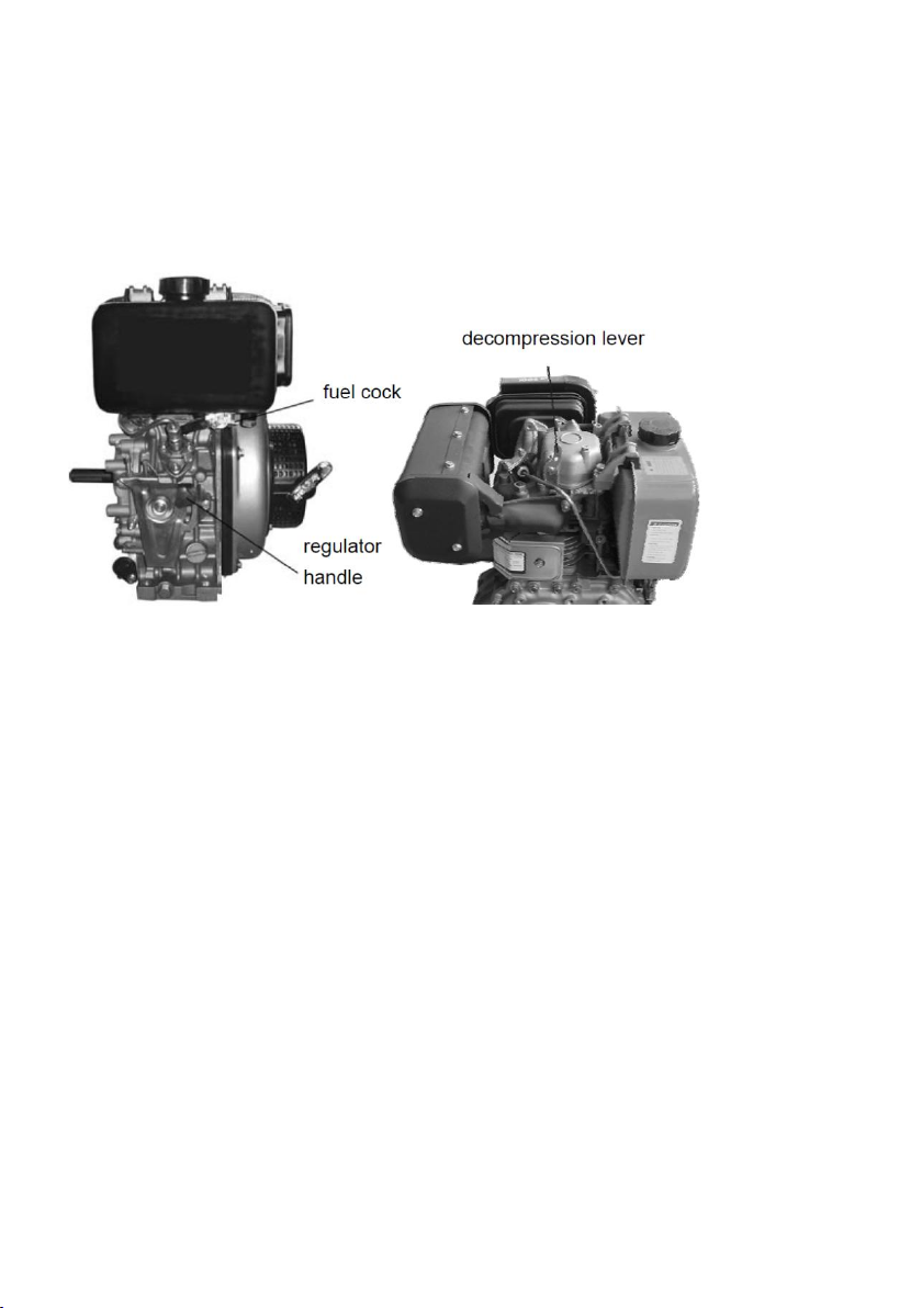
11. Set the fuel cock the “OFF” position.
12. Pull the recoil starter handles slowly, until you feel resistance. (At this
point, the decompression just begins and intake/exhaust valves are both
closed, thus the cylinder can be prevented from rust.)
13. Concerning the electric starting engine, directly turn the starting key to
“CLOSE”position.
●
The machine is best suited to the compaction of bituminous and granular
materials e.g. granular soils such as silt and clay are best compacted
using the impact force produced by a vibrating rammer.
●
Where possible the site should be graded and leveled before
commencing compaction.
●
Correct moisture content in soil is vital to proper compaction. Water acts
as a lubricant to help slide soil particles together. Too little moisture
means inadequate compaction; too much moisture leaves water-filled
voids that weaken the soil’s load-bearing ability.
●
Compaction of dry materials will be facilitated by moistening with a water
hose fitted with a sprinkler.
●
Excessive watering or water content will cause the machine to stall.
●
The optional water tank kit is recommended when the machine is used on
bituminous surfaces as the water film prevents a build up of material on
the underside of the plate.
●
The vibratory motion provides a self propelling action. Position the handle
at the opposite end of the machine to the vibrator.
●
For more information on starting and correct operating procedures of the
motor, refer to the motor operation manual supplied with the unit.
●
Increase the motor speed to the maximum setting using the hand throttle
lever, before commencing compacting.
●
The machine should be controlled by grasping the handle with both
hands and applying restraint to control the forward motion.
●
Steer the machine by moving the handle sideways to the right or left.
●
ALWAYS maintain good footing so that you do not slip and loose control
when starting or operating the machine.
●
If the optional water tank is fitted, the flow rate can be controlled by
adjusting the cock in the supply hose to sprinkler bar.
●
Inspect the water hose and its connections to ensure that they do not
leak.

9
6. CARE AND PREVENTIVE MAINTENANCE
Check the oil level in the motor crankcase daily.
Inspect the rubber anti vibration mounts for wear or deterioration.
If the optional water tank is fitted inspect the water hose and its
connections to ensure that they do not leak.
Clean the underside of the plate regularly to prevent a build up of
material.
CAUTION:
Inspection and other services should always be carried out on
hard and level ground with the engine shutdown.
Inspection and Maintenance Service Tables
To make sure your plate compactor is always in good working condition before using,
carry out the maintenance inspection in accordance with Tables 1 through 3.
TABLE 1. MACHINE INSPECTION
Item Hours of Operation
(Starting check) Every 8 hours (every day)
Loosened of lost screws Every 8 hours (every day)
Damage of any part Every 8 hours (every day)
Function of controlling system part
Every 8 hours (every day)
Vibrator oil check Every 100 hours
Vibrator oil replacement Every 200 hours
V-belt (clutch) check Every 200 hours
TABLE 2. ENGINE CHECK
(For details, see separate engine Manual)
Item Hours of Operation
Leakage of oil fuel Every 8 hours (every day)
Tightness of fastening Threads Every 8 hours (every day)
Engine oil check and replenishment
Every 8 hours (every day)
(Replenish to specified Max. level)
Engine oil replenishment At first 20 hours, then every 100 hours
Air cleaner cleaning Every 50 hours

10
TABLE 3. TIGHTENING TORQUE (in. kg/cm) Diameter
Material
6mm
8mm
10mm
12mm
14mm
16mm
18mm
20mm
4T 70 150 300 500 750 1100 1400 2000
6-8T 100 250 500 800 1300 2000 2700 3800
11T 150 400 800 1200 2000 2900 4200 5600
* 100 (6mm) 300-350 (8mm) 650-700 (10mm)
*(In case counter-part is of aluminium)
(Threads in use with this machine are all right handed)
Material and quality of material is marked on each bolt, and screw.
CAUTION:
These inspection intervals are for operation under normal conditions.
Adjust your inspection intervals based on the number hours plate
compactor is in use, and particular working conditions.
CAUTION:
Fuel piping and connections should be replaced every 2 years.
Daily Service
Check for leakage of fuel or oil.
Remove soil and clean the bottom of compaction plate.
Check engine oil.
Check for loose screws including tightness. See Table 3 above (tightening
torque), for retightening.
Changing Vibrator Oil
When changing the vibrator oil, remove the drain plug located at the
bottom-right of the vibrator, and simply tip the compactor to drain the oil. Note
that the oil will drain more easily while it is hot.
Air Filter
1. The air filter element should be cleaned because a clogged air cleaner can
cause poor engine starting, lack of power and shorten engine life
substantially.
2. To clean or replace air filter loosen the wing nut on the air filter housing
(Figure 1), remove the cover and take out air filter cartridge. If only cleaning

11
of the air filter is desired blow through the air filter cartridge from the inside,
moving a jet of dry compressed air up and down until all dust is removed.
CAUTION:
NEVER attempt to check the V-belt with the engine running.
Severe injury can occur if your hand gets caught between the
V-belt and the clutch. Always use safety gloves.
Checking and Replacing the V-belt and Clutch
After 200 hours of operation, remove the upper belt cover to check the V-belt
tension . Tension is proper if the belt bends about 10mm when depressed
strongly with finger between shafts. Loose or worn V-belts reduces power
transmission efficiency, causing weak compaction and reduces the life of the
belt itself.
CAUTION:
Whenever the compactor’s vibration becomes weak or lost
during normal operation regardless of operation hours, check
the V-belt and clutch immediately.

12
● Replacing the V-belt
Remove the upper and lower belt covers. Engage an offset wrench (13mm)
or the like to vibrator pulley (lower) fastening bolt. Engage waste cloth or the
like at midway of V-belt on the left side and while pulling it back strongly,
rotate the offset wrench clockwise so that the V-belt will come off.
● Reinstalling the V-belt
Engage V-belt to lower vibrator pulley and push the V-belt to left side of upper
clutch and, in the same manner as in removal, rotate offset wrench clockwise
so that the V-belt goes back on.
● Checking Clutch
Check the clutch simultaneously with V-belt checking. With belt removed,
check outer drum of the clutch for seizure and “V” groove for wear or damage
with your eyes. Clean the “V” groove as necessary. Wear of lining or shoe
should be checked with running check. If the shoe is worn, power
transmission becomes deficient and slipping will result.
7. TRANSPORTATION
1. Always shut off engine when transporting machine.
2. Make sure lifting device has enough capacity to hold machine (see
identification plate on machine for weight).
3. Use lifting point when lifting machine.
4. Trolley wheel as optional is used for short distance transportation.

13
8. TROUBLE SHOOTING
ENGINE TROUBLE SHOOTING
SYMPTOM POSSIBLE CAUSE SOLUTION
Difficult to start, "fuel is
available,but no
SPARK at spark plug".
Spark plug bridging? Check gap, insulation or replace spark plug.
Carbon deposit on spark plug? Clean or replace spark plug.
Short circuit due to deficient spark plug
insulation? Check spark plug insulation, replace if worn.
Improper spark plug gap? Set to proper gap.
Difficult to start, "fuel is
available,and SPARK
is present at spark
plug.
ON/OFF switch is shorted? Check switch wiring, replace switch.
Ignition coil defective? Replace ignition coil.
Improper spark gap, points dirty? Set correct spark gap and clean points.
Condenser insulation worn or short
circuiting? Replace condenser.
Spark plug wire broken or short
circuiting? Replace defective spark plug wiring
Difficult to start, "fuel is
available,spark is
present and
compression is normal"
Wrong fuel type? Flush fuel system, and replace with correct
type of fuel.
Water or dust in fuel system? Flush fuel system.
Air cleaner dirty? Clean or replace air cleaner.
Difficult to start, "fuel is
available,spark is
present and
compression is low.
Suction/exhaust valve stuck or
protruded? Re-seat valves.
Piston ring and/or cylinder worn? Replace piston rings and or piston.
Cylinder head and/or spark plug not
tightened properly? Torque cylinder head bolts and spark plug.
Head gasket and/or spark plug gasket
damaged? Replace head and spark plug gaskets.
No fuel present at
carburetor.
Fuel not available in fuel tank? Fill with correct type of fuel.
Fuel cock does not open properly?
Apply lubricant to loosen fuel cock level,
replace if necessary.
Fuel filter clogged? Replace fuel filter.
Fuel tank cap breather hole clogged? Clean or replace fuel tank cap.
Air in fuel line? Bleed fuel line.
"Weak in power"
compression is proper
and does not misfire.
Air cleaner not clean? Clean or replace air cleaner.
Improper level in carburetor? Check float adjustment, re-build carburetor.
Defective Spark plug? Clean or replace spark plug
"Weak in power"
compression is proper
but misfires
Water in fuel system? Flush fuel system, and replace with correct
type of fuel.
Dirty spark plug? Clean or replace spark plug.
Ignition coil defective? Replace ignition coil.
Engine overheats.
Spark plug heat value improper? Replace with correct type of spark plug.
Correct type of fuel? Replace with correct type of fuel.
Cooling fins dirty? Clean cooling fins.
Rotational speed
fluctuates.
Governor adjusted correctly? Adjust governor.
Governor spring defective? Replace governor spring.
Fuel flow restricted? Check entire fuel system for leaks or clogs.
Recoil starter
malfunction.
Recoil mechanism clogged with dust and
dirt? Clean recoil assembly with soap and water.
Spiral spring loose? Replace spiral spring.
SYMPTOM POSSIBLE CAUSES SOLUTION
Travel speed too low,
and vibration is weak.
Engine speed too low? Set engine speed to correct RPM.
Clutch slips? Check or replace clutch.
V-belt slips? Adjust or replace V-belt.
Excessive oil in vibration? Drain excess oil and fill to proper level.
Malfunction in vibrator housing? Check eccentric, gears and counter weights.
Bearing Failure? Replace Bearing
Insufficient engine output? Check engine, compression etc.

14
9. EXPLANATION OF SYMBOLS
DANGER!
Engines emit carbon monoxide; operate
only in well-ventilated area.Read the
Operation Manual for machine information.
No sparks, flames, or burning objects
near the machine. Shut off the engine
before refueling. Use only clean, filtered
unleaded Diesel.
CAUTION !
Lifting point.
CAUTION!
Read and understand the supplied
OperationManual before operating the
machine.Failure todo so increase the risk
of injury to yourself orothers.
WARNING!
Always wear hearing and eye protection
when operating this machine.

15
Guaranteed sound power level in dB(A).
Forward and backward

16
10. EXPANDED VIEW AND PART LISTS
Part 1

17
ITEM NO PART NO DESCRIPTION QTY
1 3001000-2 BASE PLATE 1
2 3002000 VIBRATION BOX 1
3 0700018-45 BOLT M18 x 45-GB70 4
4 0970018 WASHER 18-GB97 4
5 0930018 SPRING WAHSER18-GB93 4
6 3003000-A ENGINE MOUNTING PLATE 1
7 3004000 ADJUSTING PLATE 4
8 0410012 NUT12-GB41 4
9 0970012 WASHER 12-GB97.1 4
10 0930012 SPRING WAHSER 12-GB93 4
11 3005000 FRAME ASSEMBLY 1
12 0700012 BOLT M12 x 20-GB70 4
13 0930012 SPRING WASHER12-GB93 4
14 3000001-1 DIESEL ENGINE 1
15 0700010 BOLT M10 x 30-GB70 4
16 0930010 SPRING WASHER10-GB93 4
17 0970010 WASHER10-GB97.1 4
18 3006000 HANDLE ASSEMBLY 1
20 3007000 BELT GUARD 1
21 3008000-1 ENGINE PULLEY FOR DIESEL 1
22 0700006 BOLT M6 x 15-GB70 4
23 0930006 SPRING WASHER6-GB93 4
24 0970006 WASHER6-GB97.1 4
25 0700008-20 BOLT M8 x 20-GB70 1
26 0930008 SPRING WASHER8-GB93 1
27 0970008 WASHER8-GB97.1 1
28 0700008-20 BOLT M8 x 20-GB70 1
29 3009000 SPRING 1
30 3010000 TROLLEY WHEEL (OPTIONAL) 1
31 3011000-1 V-BELT 1

PART 2
ITEM NO PART NO DESCRIPTION QTY
32 3001001-1 BASE PLATE 1
33 3001002 VIBRATION DAMPER 4
34 0970012 WASHER12-GB97 4
35 0617012 NUT M12-GB6170 4
36 3001003 EXTENSION PLATE 2
37 0970020 WASHER-GB97 6
38 0930020 SPRING WASHER-GB93 6
39 0578020 BOLT M20X45-GB5783 6

PART 3

ITEM NO
PART NO DESCRIPTION QTY
40 3002001 EXCITER BOX 1
41 3002002 BOX COVER 1
42 0700008-25 BOLT M8 x 25-GB70 9
43 0930008 SPRING WASHER8-GB93 30
44 0119008 PIN BOLT8-GB119 2
45 0283006 BEARING32206-GB283 2
46 0987752 OIL SEAL φ52 x φ28 x 7-GB9877.1 1
47 3002003 BEARING COVER 1
48 0700008-20 BOLT M8 x 20-GB70 12
49 3002004 PULLEY 1
50 3002005 WASHER 1
51 0109608 KEY C20 x 8-GB1096 1
52 0578308 BOLT M8 x 20-GB5783 1
53 3002006 BEARING COVER 2
54 0276006 BEARING60206-GB276 2
55 3002007 PINCH CLAMP 1
56 3002008 BOLT M20 1
57 3002009 BOLT 1
58 0854010 WASHER10-GB854 10
59 0617010 NUT M10-GB6170 1
60 0910003 SPLIT PIN φ2.5 x 20-GB91 1
61 3002010 SPINDLE 1
62 3002011 UNBALANCE WEIGHT 1
63 0894040 RETAINING RING40-GB894 2
64 3002013 DIRECTION PIN 1
65 0730008 BOLT M8 x 25 1
67 3002014 SPINDLE 1
68 3002015 DIRECTION HOUSING 1
69 3002016 ROTARY COVER 1
70 3002017 WAHSER 1
71 0930005 SPRING WASHER5-GB93 4
72 0700005 BOLT M5 X 15-GB70 4
73 3002018 SPINDLE 1
Table of contents
Popular Garbage Disposal manuals by other brands

InSinkErator
InSinkErator Model LC-50 installation manual

Kenmore
Kenmore Garbage Disposal Installation & use manual

GE
GE ZCGP150LII INSTALL owner's manual

IMC
IMC 04 SERIES Installation, operating and maintenance manual

Leafield Environmental
Leafield Environmental EnviroHub installation guide

Whirlpool
Whirlpool GC2000PE2 parts manual