3901726 JobSmart 4 Gallon Air Compressor Assembly & Operating Instructions 7
Handle: Rubber gripped handle for easy transport.
Air Regulator: Controls the air flow pressure. Turn regulator
clockwise to increase air pressure, counter-clockwise to
decrease.
Air Chuck: Allows for fast, easy connection to an air hose.
Tank Drain Valve: Open to allow moisture and compressed
air to be released from the Air Tank.
WARNING The Tank Drain Valve should always be
opened slowlv to avoid damage to equipment and
possible injury.
Oil Breather Cap: As the compressor motor operates
pressurized air must be released from the crank case. The oil
breather cap allows built up air to escape, while shielding your
air compressor from airborne impurities.
Air Tank: Powder coated steel tank, with a 4 gallon capacity,
stores the compressed air until it is needed.
Power Switch: Red tipped power switch turns the air
compressor on and off. When switch is pulled up, compressor
is turned ON. When switch is pushed down, compressor is
turned OFF.
Note: Always make sure that compressor Power Switch is in
the OFF position before performing any maintenance or
plugging the compressor Into a power supply.
Pressure Gauges: Dual gauges indicate the amount of air
pressure built up in the air tank, as well as the air pressure
being delivered to the air chuck.
Safety Valve: Relieves pressure from the Air Tank in the
event of excessive pressure build up. Preset at factory. Do not
attempt to make any adjustments to the Safety Valve.
Periodically pull ring on the Safety Valve end to check that it is
working properly.
Air Filter: Heavy duty metal air filter keeps your compressor
running clean by filtering out impurities.
ASSEMBLY
Before performing any assembly or maintenance, make sure compressor is turned off and unplugged
from the power supply.
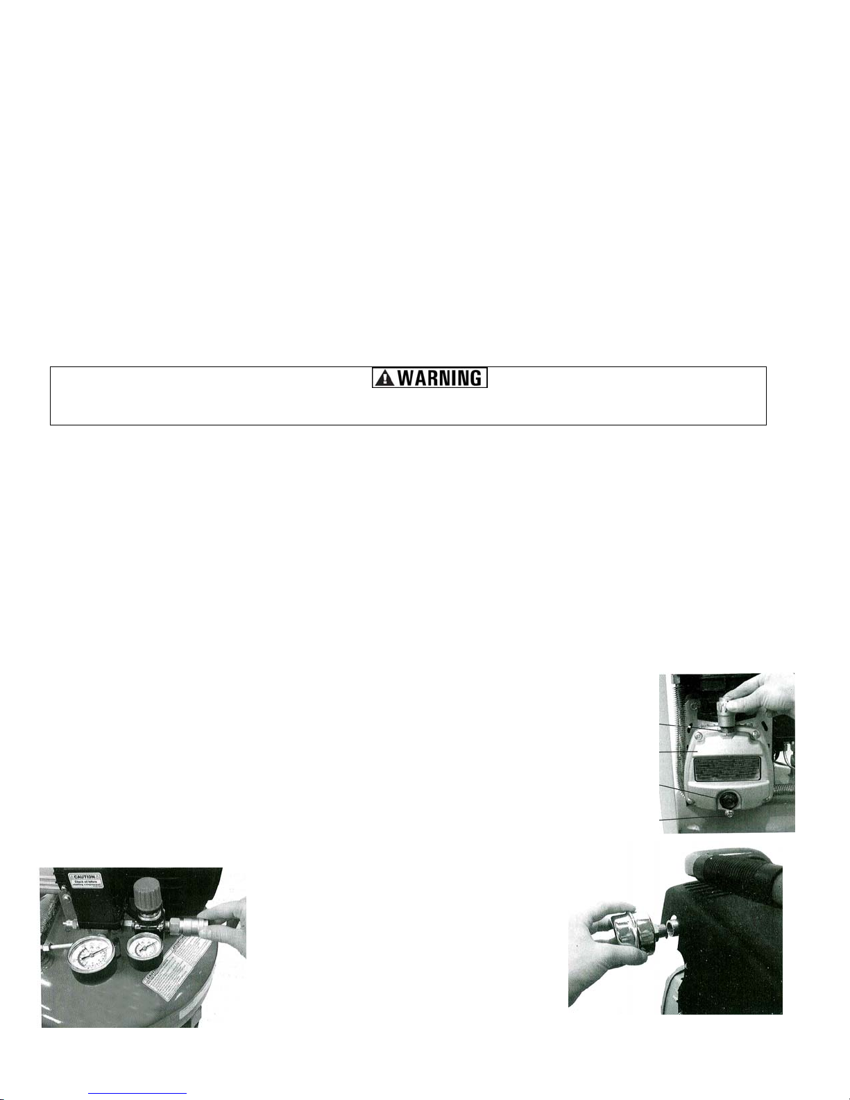
Your air compressor is shipped without oil in the crankcase. YOU MUST ADD OIL TO THE CRANKCASE
BEFORE STARTING THE AIR COMPRESSOR.
1. Place compressor on level ground.
2. Remove the Oil Shipping Plug from the Oil Fill hole, located on the top of the crankcase cover at the rear.
3. Pour the oil into the Oil Fill hole, until the oil level rises to the center of the red dot on the Oil Sight Glass.
Note: This compressor uses only SAE 5W-30 motor oil.
4. Install the Oil Breather Cap into the Oil Fill hole.
5. Firmly hand-tighten the Oil Breather Cap by turning clockwise.
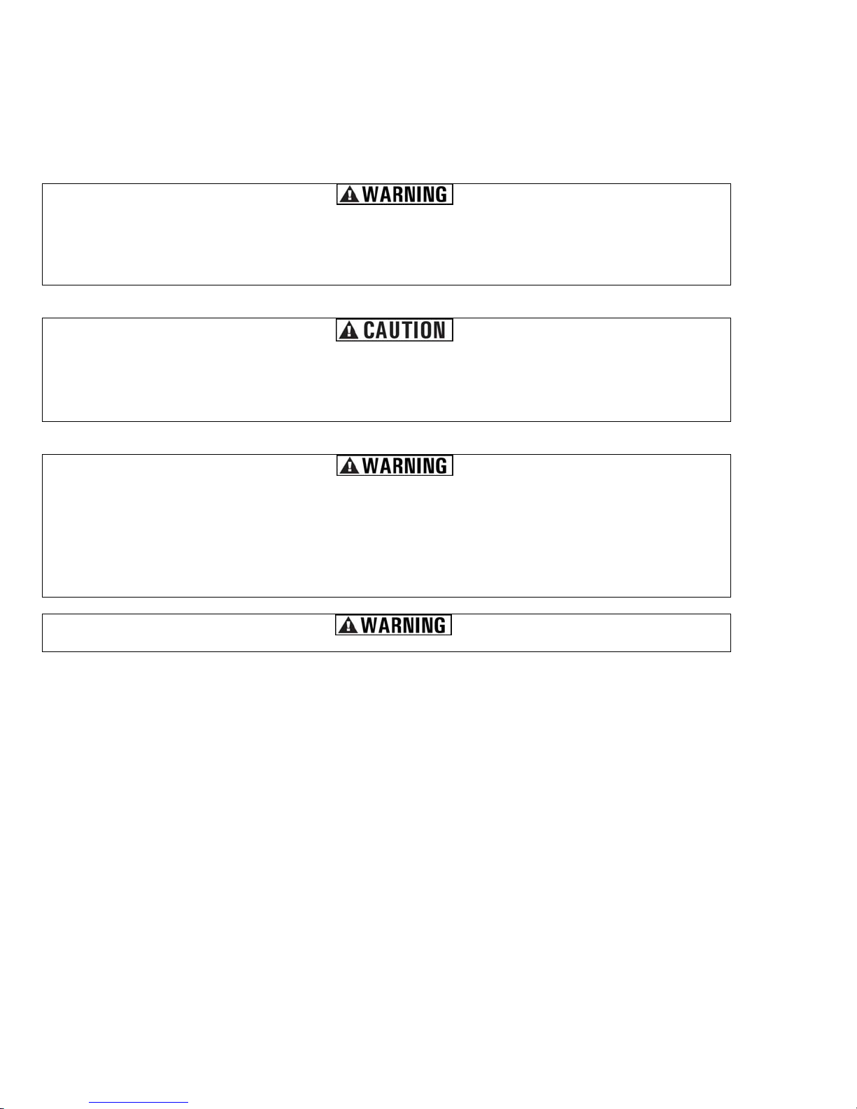
lnstalling the Air Chuck
Note: Use a sealant tape on the threads of the Air Chuck to prevent air leakage.
1. Thread the Air Chuck into the Air Regulator by turning the Air Chuck clockwise.
2. Securely tighten the Air Chuck in place with a wrench.
Note: DO NOT over tighten Air Chuck.
lnstalling the Air Filter
The metal Air Filter is installed into the threaded port of the cylinder head.
1. Thread the Air Filter into the Cylinder Head by turning Air Filter clockwise.
2. Securely tighten the Air Filter in place with a wrench. (See Figure 4)
Note: DO NOT over tighten Air Filter.
Figure 4
lnstalling the
Air Filter
Figure 3
lnstalling the
Air Chuck
Figure 2
lnstalling the
Oil & Oil
Breather Cap
Oil Fill
Crankcase
Sight Glass
Drain Plug