JoeTap JADE524-SS03A User manual
This appliance is intended for use in
commercial establishments, where all
operators are familiar with the appliance
use, limitations and associated hazards.
Operating instructions and warnings
must be read and understood by all
operators and users.
2060 Cessna Drive
Suite 100
Vacaville, CA 95688
www.joetap.com
TECHNICAL SUPPORT:
707-448-5151
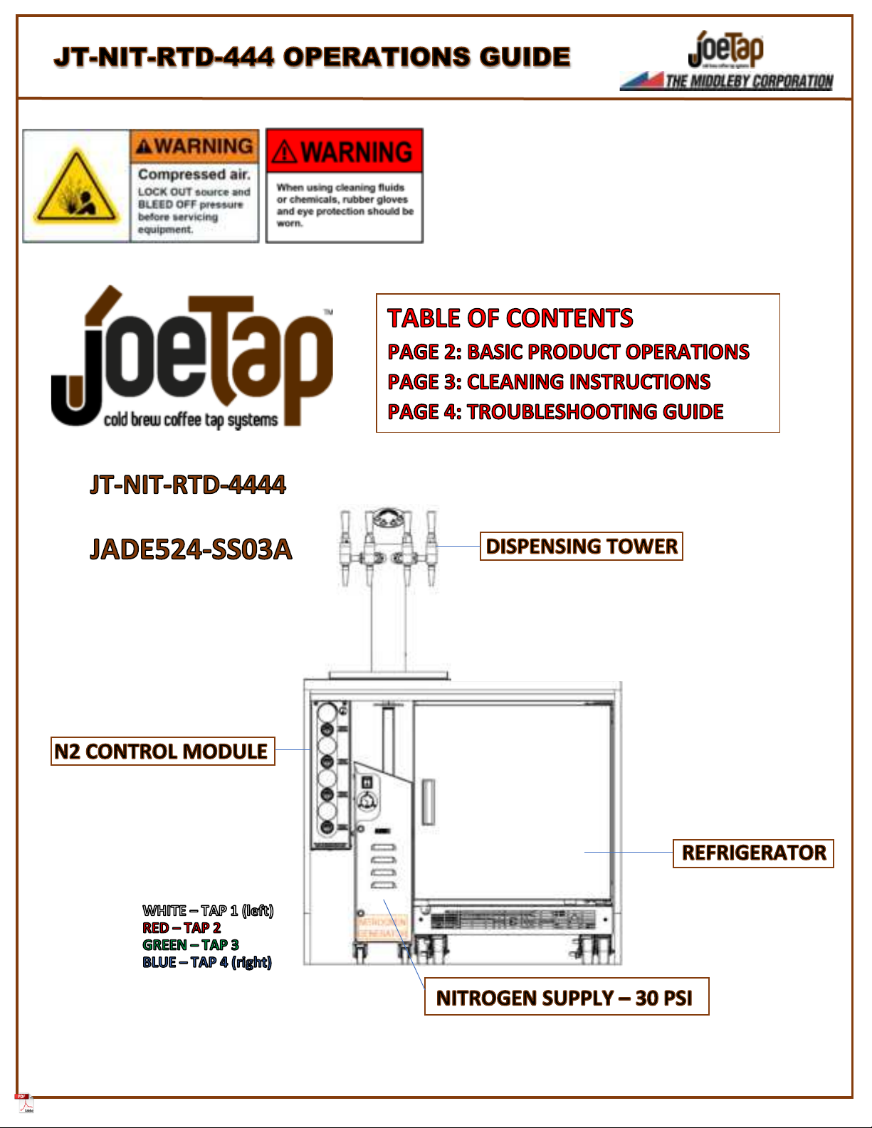
JOETAP MODEL:
ULINE COOLER MODEL:
•INPUT PRESSURE 30 PSI
•Independent Nitrogen infusion
pressure adjustments and gauges
for each tap: Recommended setting
12 PSI
•Solenoid controlled N2 activation
for each tap
•Color Coded nitrogen supply lines
o
o
o
o
•Four taps/Four different beverages
•Independent Nitrogen Infusion
Control for each tap
•Illuminated switches for visual
confirmation of Nitro activation
•LED ON = Nitro Active
•Cold storage for up to 4
kegs (2.5 or 3 gallon/ea.)
•Independent temperature
and defrost controls
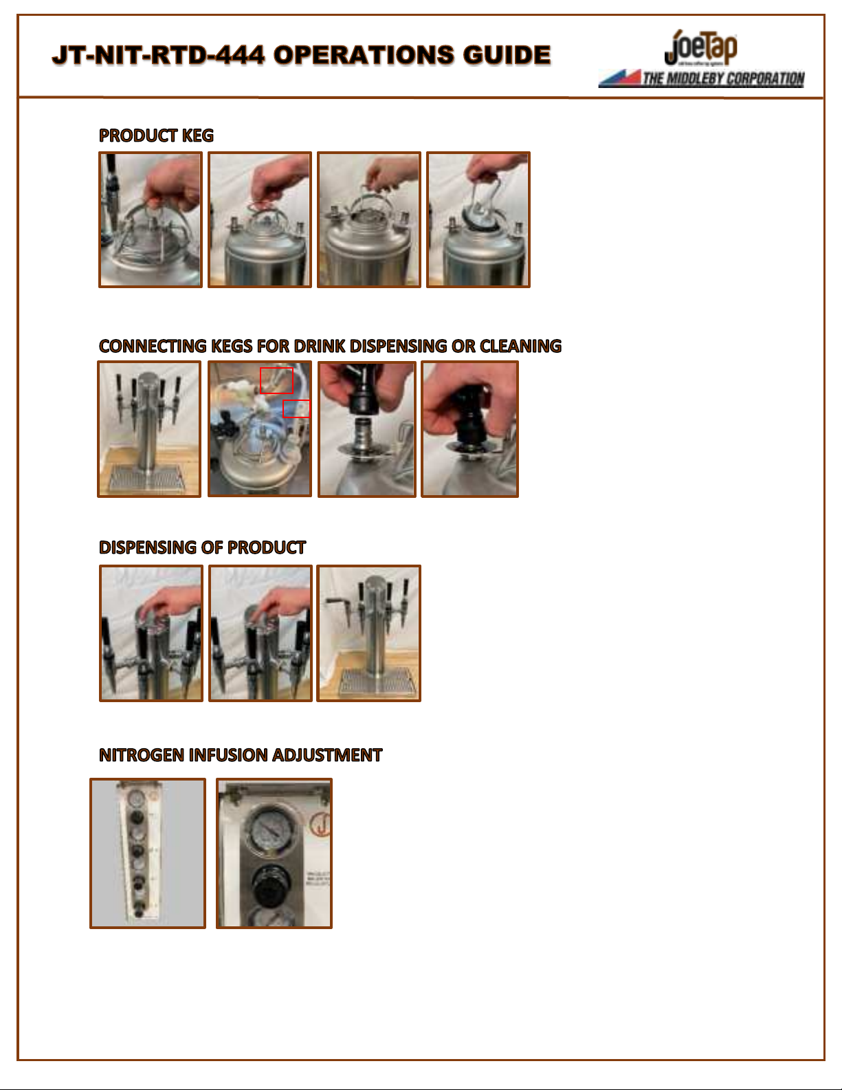
Relieve any static pressure in the product keg
by lifting the ring on the pressure relief valve.
Once drained of pressure, lift the locking
mechanism of the tank lid and press
downward on the lid to push it inside the tank.
Twist the lid sideways and tilt it slightly to
remove the lid from the tank. To re-insert and
lock the lid, reverse the steps as shown.
Using the Tap Numbers printed on the top of
the Dispensing Tower as a guide, connect the
labelled Product Supply (BLACK) and Nitrogen
Supply (GREY) lines to the correct product keg
by placing them on the keg connectors, lifting
connector sleeve upward and firmly pressing
downward until the connector locks into
place. Product lines are labelled 1-4 from left
to right to correspond with faucets on the
tower which are also 1-4 left to right.
Each of the 4 product taps can pour both nitrogen-infused and
non-infused beverages. This option is selected by pressing the
buttons at the top of the Dispensing Tower:
ILLUMINATED BUTTON = NITROGEN INFUSION
NON-ILLUMINATED BUTTON = NO NITROGEN INFUSION
Once the desired nitrogen option has been selected, pull the tap
handle to a fully horizontal position to dispense product. It is
important that the buttons are left in an illuminated position when
the system will be idle for extended periods, such as overnight.
The regulators located on the front of the Nitrogen Control Module allow for
independent control of nitrogen infusion for beverages at each tap. The gauges
will indicate the current pressure setting for each regulator. Increasing the
nitrogen pressure by turning the regulator knob CLOCKWISE will increase the
amount of nitrogen infusion in the beverage. Optimal infusion pressures will vary
depending on the type of beverage being dispensed, but generally, setting the
infusion pressures between 9 and 12 PSI will provide the desired infusion levels.
Any changes should be done in small steps as alterations of 1 PSI will have a
noticeable effect on product pours. When decreasing pressures, multiple pours
are necessary to allow the pressures to stabilize.
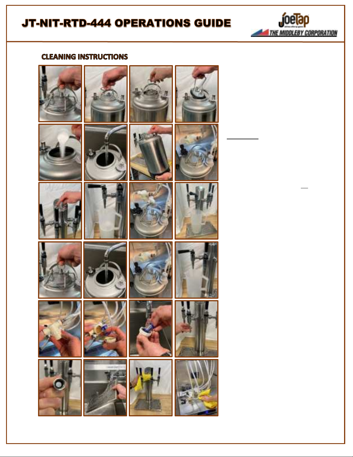
Relieve any static pressure in the product keg
by lifting the ring on the pressure relief valve.
Once drained of pressure, lift the locking
mechanism of the tank lid and press
downward on the lid to push it inside the tank.
Twist the lid sideways and tilt it slightly to
remove the lid from the tank.
STERA-SHEEN®: Mix one, 2-ounce packet of
Stera-Sheen® sanitizer powder with 2 gallons /
7-1/2 liters of 100°F / 38°C potable water in a
clean product tank. Gently swirl water in tank
to mix sanitizer. Connect ‘Product 1’ and ‘N1’
ball lock connectors to keg.
Ensure all Nitro select switches are not
illuminated. Open tap #1 until approximately
64 ounces of sanitizer has dispensed. Leaving
the ‘N1’ connector in place, switch the liquid
Ball-Lock connector to ‘Product 2’. Open tap
#2 until 64 ounces of sanitizer has been
dispensed. Repeat this process for taps #3 and
#4. Disconnect keg and relieve pressure.
Allow sanitizer to remain in the system for 5
minutes. Rinse the keg well and refill with 100°
water. Follow the same procedure as the
sanitizing process by connecting the ‘Product
1’ and ‘N1’ connectors to keg. Dispense 64
ounces of water from Tap #1 and continue the
rinsing process for Taps 2 –4. Disconnect keg
and relieve pressure.
Open each tap to relieve pressure from lines.
Disassemble each of the 4 product filters. If
they are too tight to unscrew by hand, use a
tool with a protective barrier to prevent
damage to the housing. Remove and rinse the
filter membranes and lower housings under
warm clean water. Reassemble the filter
housings. Unscrew all 4 Tap Nozzles and verify
the holes in the Diffusion Plates are clear of
debris.
If debris is present, wash with sanitizer over a
bucket to prevent losing nozzle internals.
Reinstall nozzles. Wash and sanitize the Drip
Tray. Using a towel moistened with sanitizer,
wipe down the tower assembly and
refrigerator.
CLEANING PROCESS COMPLETE
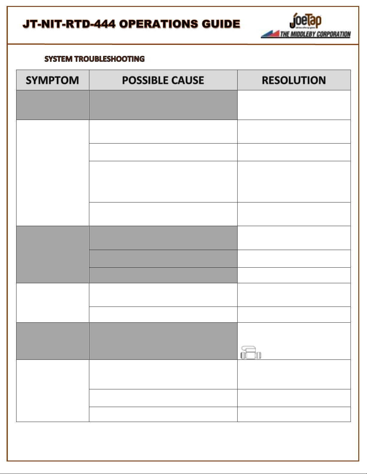
NO PRODUCT POUR
ALL FAUCETS
NO NITROGEN PRESSURE
VERIFY THAT THE NITROGEN GENERATOR IS PLUGGED
IN AND THE POWER SWITCH IS IN THE ‘ON’ POSITION.
IF A GAS CYLINDER IS BEING USED, VERIFY SUFFICIENT
PRESSURE WITHIN THE TANK BY CHECKING THE
PRESSURE GAUGE ON THE OUTPUT REGULATOR.
NO PRODUCT POUR
SINGLE FAUCET
NO PRODUCT IN KEG
REMOVE BOTH THE GRAY AND BLACK CONNECTORS
FROM KEG AND RELEASE THE PRESSURE BY LIFTING
THE RING ATOP THE PRESSURE RELIEF VALVE.
REMOVE LID AND VERIFY AMPLE PRODUCT IN KEG.
BAD CONNECTION AT PRODUCT KEG
REMOVE BOTH THE GREY AND BLACK BALL-LOCK
CONNECTORS FROM THE KEG AND RE-INSERT THEM
FIRMLY.
PRODUCT FILTER IS CLOGGED
REMOVE BLACK BALL-LOCK CONNECTOR FROM
AFFECTED PRODUCT KEG AND BRIEFLY OPEN THE
AFFECTED TAP TO REMOVE PRESSURE FROM THE
LINE. UNSCREW BOTTOM OF FILTER HOUSING, THEN
REMOVE FILTER ELEMENT INSIDE. CLEAN ELEMENT
WITH APPROVED SANITIZER AND RE-INSTALL.
RECONNECT KEG AND VERIFY OPERATIONS.
NOZZLE AT TAP IS CLOGGED
REMOVE NOZZLE FROM DISPENSING FAUCET AND
CHECK FOR BLOCKAGE. IF BLOCKAGE IS PRESENT,
REMOVE NOZZLE INTERNALS AND CLEAN WITH
APPROVED SANITIZER.
NITRO POUR ONLY
ALL FAUCETS
POOR CONNECTION TO POWER SUPPLY
VERIFY THAT THE LOW-VOLTAGE POWER SUPPLY
CONNECTOR IS PROPERLY INSERTED INTO THE BACK
OF THE NITROGEN CONTROL MODULE AT THE LOWER
SECTION OF THE REAR PANEL.
PRIMARY NITROGEN PRESSURE TOO HIGH
VERIFY PRESSURE OUTPUT OF NITROGEN SOURCE IS
SET TO 30PSI. ADJUST OUTPUT REGULATOR AS
NEEDED.
ALL PRODUCT HAS BEEN EXPOSED TO NITROGEN
PRESSURE FOR MORE THAN 48 HOURS
DISCARD PRODUCT AND CONNECT A KEG OF FRESH
PRODUCT TO AFFECTED TAPS.
NITRO POUR ONLY
SINGLE FAUCET
PARTIALLY CLOGGED NOZZLE/MISSING RESTRICTOR DISK
REMOVE NOZZLE FROM DISPENSING FAUCET AND
CHECK FOR BLOCKAGE OR MISSING RESTRICTOR DISK.
IF BLOCKAGE IS PRESENT, REMOVE NOZZLE
INTERNALS AND CLEAN WITH APPROVED SANITIZER.
PRODUCT HAS BEEN EXPOSED TO NITROGEN PRESSURE
FOR MORE THAN 48 HOURS
DISCARD PRODUCT AND CONNECT A KEG OF FRESH
PRODUCT TO AFFECTED TAPS.
NON-NITRO POUR
ONLY –SINGLE
FAUCET
MANUAL NITROGEN SHUT-OFF VALVE IS CLOSED
VERIFY THAT THE MANUAL NITROGEN SHUT-OFF
VALVES LOCATED AT THE BASE OF THE TOWER,
UNDER THE COUNTERTOP, ARE IN THE OPEN
POSITION.
NITRO CARRYOVER
WHEN SWITCHING
FROM NITRO POUR
TO NON-NITRO POUR
INFUSION REGULATOR SET TOO HIGH
AT THE FRONT OF THE NITROGEN CONTROL MODULE,
PULL THE KNOB OF THE AFFECTED REGULATOR TO
UNLOCK IT. SLIGHTLY ROTATE COUNTER-CLOCKWISE
AND CONDUCT A TEST POUR. CONTINUE
ADJUSTMENT AND TEST AS NEEDED. (9-12PSI)
PRIMARY NITROGEN PRESSURE TOO HIGH
VERIFY PRESSURE OUTPUT OF NITROGEN SOURCE IS
SET TO 30PSI. ADJUST OUTPUT REGULATOR AS
NEEDED.
PRODUCT HAS BEEN EXPOSED TO NITROGEN PRESSURE
FOR MORE THAN 48 HOURS
DISCARD PRODUCT AND CONNECT A KEG OF FRESH
PRODUCT TO AFFECTED TAPS.
This manual suits for next models
1
Other JoeTap Accessories manuals


