JoeTap JT-NIT-RTD-4444 User manual

1
2060 Cessna Drive
Suite 100
Vacaville, CA 95688
www.joetap.com
TECHNICAL SUPPORT:
707-448-5151
This appliance is intended for commercial use only and is intended for use in dispensing brewed
beverage products for human consumption. No other use is recommended or authorized by the
manufacturer or its agents.
This appliance is intended for use in commercial establishments, where all operators are familiar with
the appliance use, limitations and associated hazards. Operating instructions and warnings must be
read and understood by all operators and users.
Except as noted, this piece of equipment is made in the USA and has American sizes on hardware. All
metric conversions are approximate and can vary in size.
The following trouble shooting, component views and parts lists are included for general reference, and are intended
for use by qualified service personnel.
JOETAP MODEL:
ULINE COOLER MODEL:
SYSTEM REQUIRES USE OF COMPRESSED
NITROGEN FOR PROPER OPERATION.
NITROGEN CAN BE SUPPLIED VIA
NITROGEN GENERATOR OR COMPRESSED
GAS CYLINDERS. NITROGEN SUPPLY
DIAGNOSTICS ARE NOT COVERED IN THIS
MANUAL.

2
•Four taps/Four different beverages
•Independent Nitrogen Infusion
Control for each tap
•Illuminated switches for visual
confirmation of Nitro activation
•LED ON = Nitro Active
•INPUT PRESSURE 30 PSI
•Independent Nitrogen infusion
pressure adjustments and gauges
for each tap: Recommended setting
12 PSI
•Solenoid controlled N2 activation
for each tap
•Color Coded supply lines
o
o
o
o
•Cold storage for up to 4
kegs (2.5 or 3 gallon/ea.)
•Independent temperature
and defrost controls
•PAGE 2 –SYSTEM OVERVIEW
•PAGE 3 –COMPONENT OVERVIEW
•PAGES 4-5 –OPERATIONAL OVERVIEW
•PAGE 6 –NITRO BEVERAGE CALIBRATION
•PAGE 7 –NITRO TROUBLESHOOTING GUIDE
•PAGE 8 –CONTROL SYSTEM WIRING DIAGRAM
•PAGE 9 –NITRO COMPONENT REPLACEMENT GUIDE
•PAGE 10 –REFRIGERATOR OPERATIONS
•PAGE 11 –REFRIGERATOR PROGRAMMING/ERROR CODES
•PAGE 12 –REFRIGERATOR TROUBLESHOOTING GUIDE
•PAGES 13-15 –REFRIGERATOR INVERTER DIAGNOSTICS/REMOVAL AND COMPRESSOR DIAGNOSTICS
•PAGES 16-21 –REFRIGERATOR UI BOARD/HARNESS REPLACEMENT INSTRUCTIONS
•PAGE 22 –QUICK REFERENCE PARTS GUIDE
•PAGES 23-25 –CLEANING INSTRUCTIONS

3
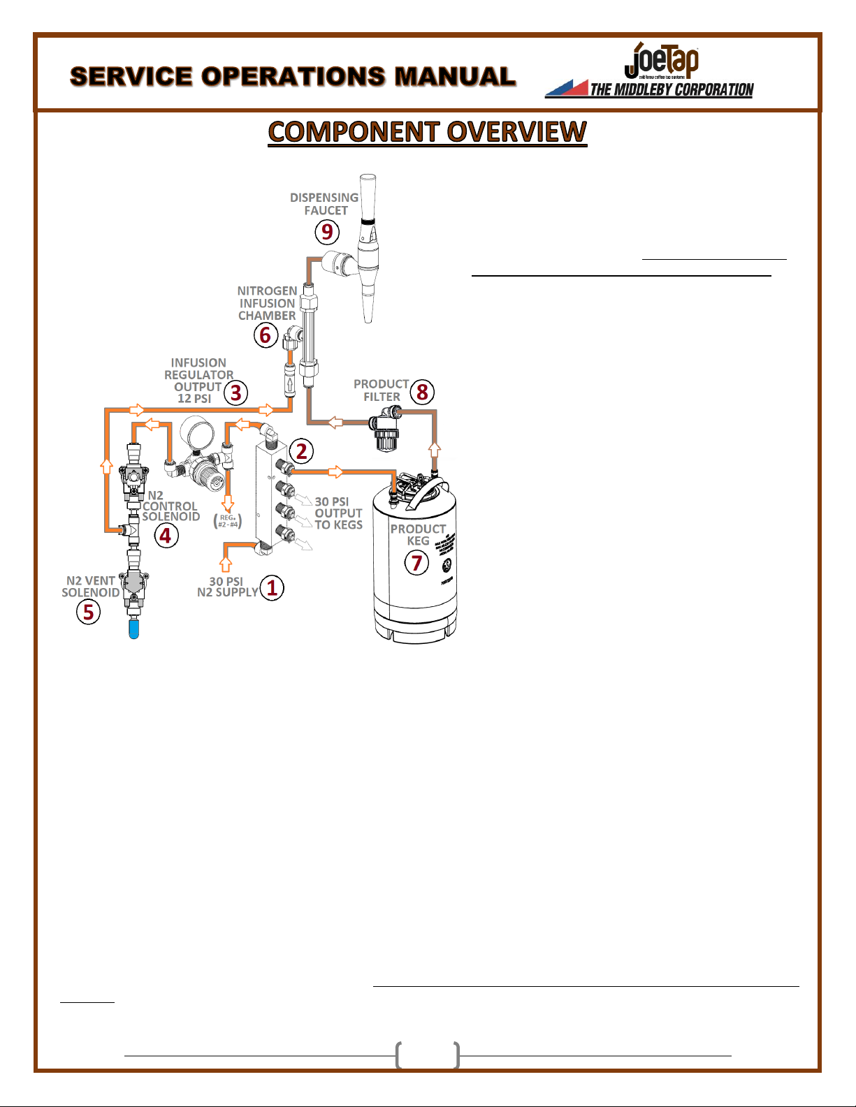
1. 30 PSI N2 SUPPLY INPUT
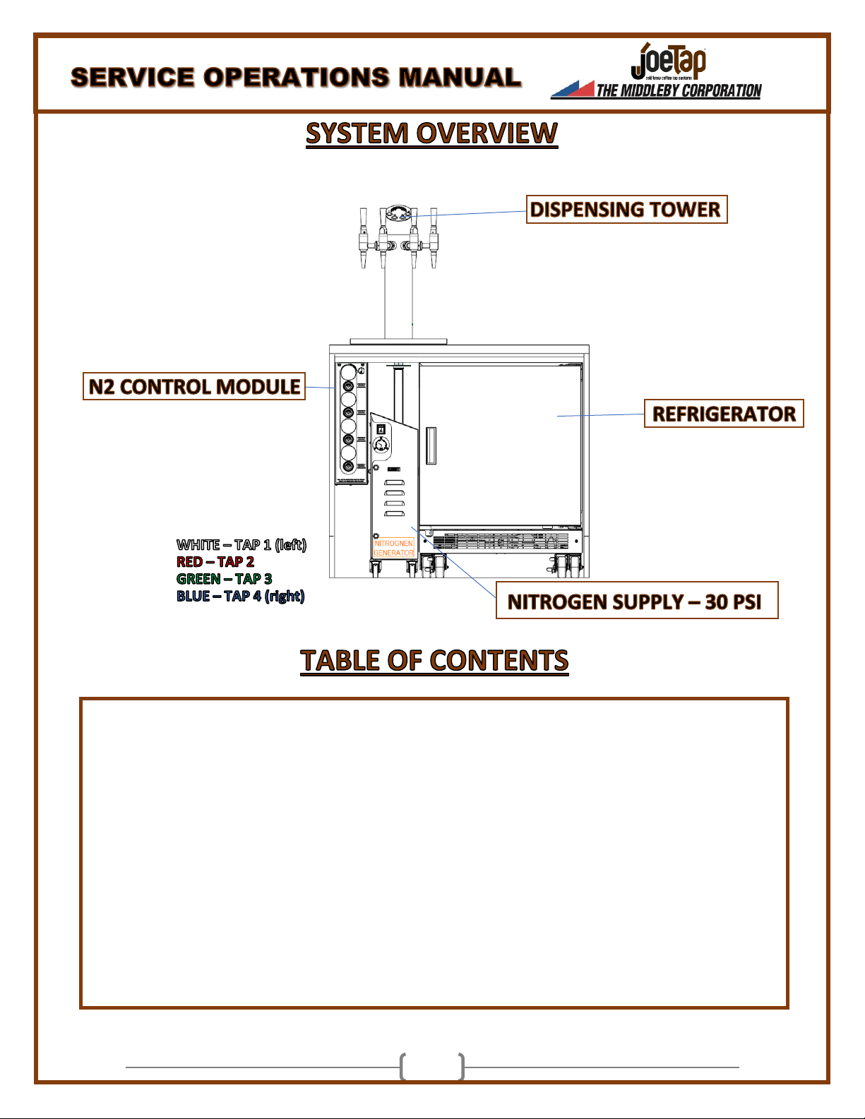
LOCATION: REAR PANEL OF N2 CONTROL MODULE.
N2 supplied via a Nitrogen generator or compressed gas cylinder.
Adjustments to this pressure can be made via a regulator at the
output of either nitrogen source. Supply pressure dictates the
amount of pressure displacing liquid from the product keg.
Factory recommended setting: 30 PSI (50PSI MAX)
2. NITROGEN DISTRIBUTION BLOCK
LOCATION: INSIDE N2 CONTROL MODULE
Distributes incoming N2 Pressure to 4 separate kegs in the
refrigerator. These pressures are not independently adjustable.
3. INFUSION REGULATORS (X4)
LOCATION: FRONT OF N2 CONTROL MODULE
Regulates N2 Pressure to each tap for proper infusion with liquid
product within the N2 Infusion Chamber (6). Easily adjusted at
the front of N2 Control Module. Increasing this pressure will add
more froth to final product.
Factory recommended setting: 12 PSI.
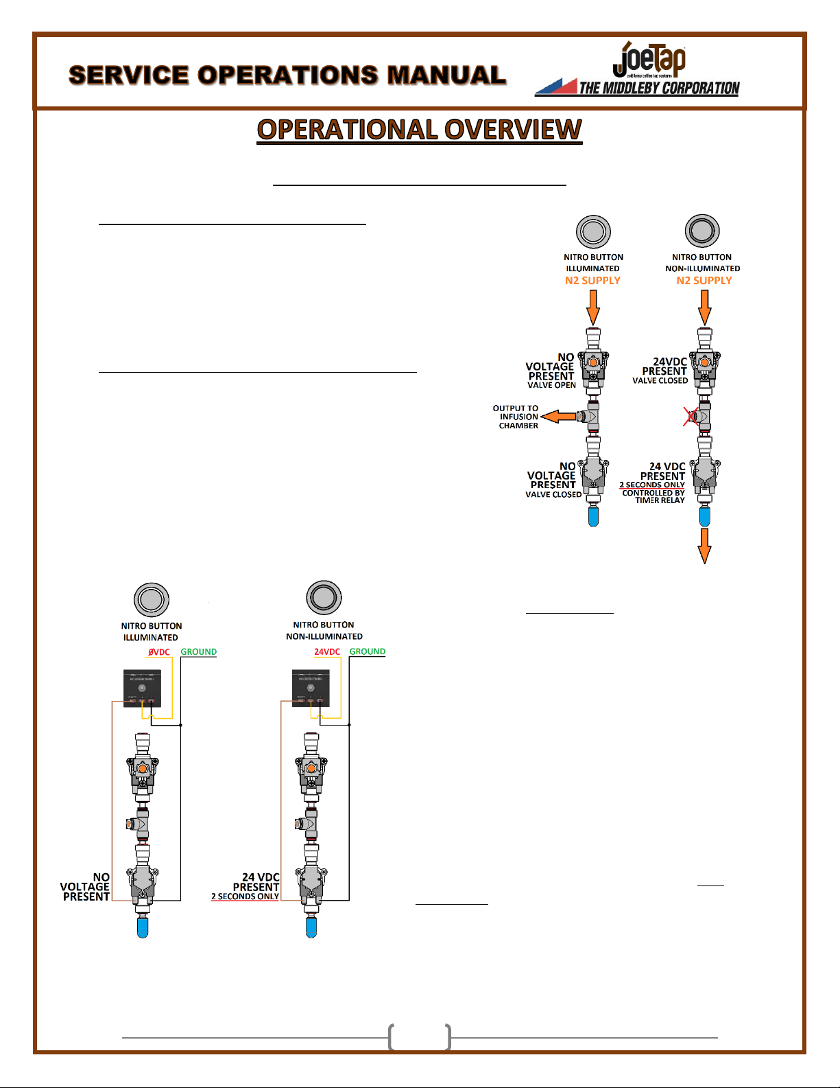
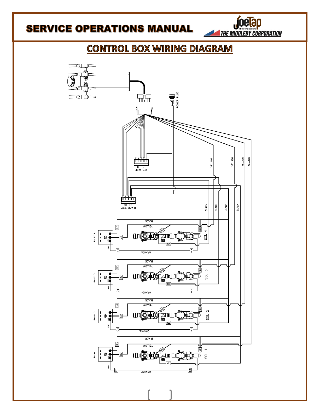
4. N2 CONTROL SOLENOID (X4 -Normally
Open/24VDC/88-90Ω)
LOCATION: INSIDE N2 CONTROL MODULE.
Activated by the Nitrogen Select buttons at the top of the
Dispensing Tower, the N2 Control Solenoids determine the
presence of N2 pressure at the Infusion Chamber. These valves
are NORMALLY OPEN. An illuminated N2 Select Button DOES
NOT apply 24VDC to the valve, allowing a nitrogen infused
beverage to be dispensed.
5. N2 VENT SOLENOID (X4 -Normally Closed/24VDC/88-90Ω)
LOCATION: INSIDE N2 CONTROL MODULE.
When N2 supply pressure to the Infusion Chamber is stopped by the N2 Control Solenoid, any static N2 pressure in the supply line is vented
through the N2 Vent Solenoid for 2 seconds. This is controlled via Timer Relays inside the N2 Control Module.
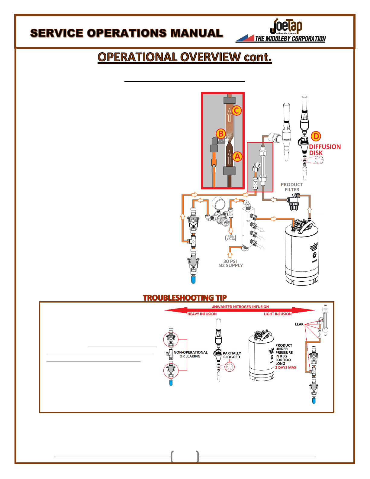
6. NITROGEN INFUSION CHAMBER (X4)
LOCATION: INSIDE DISPENSING TOWER
Nitrogen pressure controlled by the N2 Control Solenoid is blended with liquid product from the kegs to produce a nitrogen infused beverage.
7. PRODUCT KEG (UP TO 4)
LOCATION: INSIDE REFRIGERATOR
Rated at 2.5 or 3 gallons, these product kegs store beverage products prepared by the customer. Liquid is forced from the kegs by incoming
Nitrogen pressure at 30 PSI. *NOTE* Storing product kegs under Nitrogen pressure for more than 48 hours will saturate the product with
Nitrogen gas and cause frothy beverages to be dispensed at all times.
8. PRODUCT FILTER (X4)
LOCATION: INSIDE REFRIGERATOR
A removable and cleanable particulate filter that prevents clogging of smaller orifices within the dispensing tower
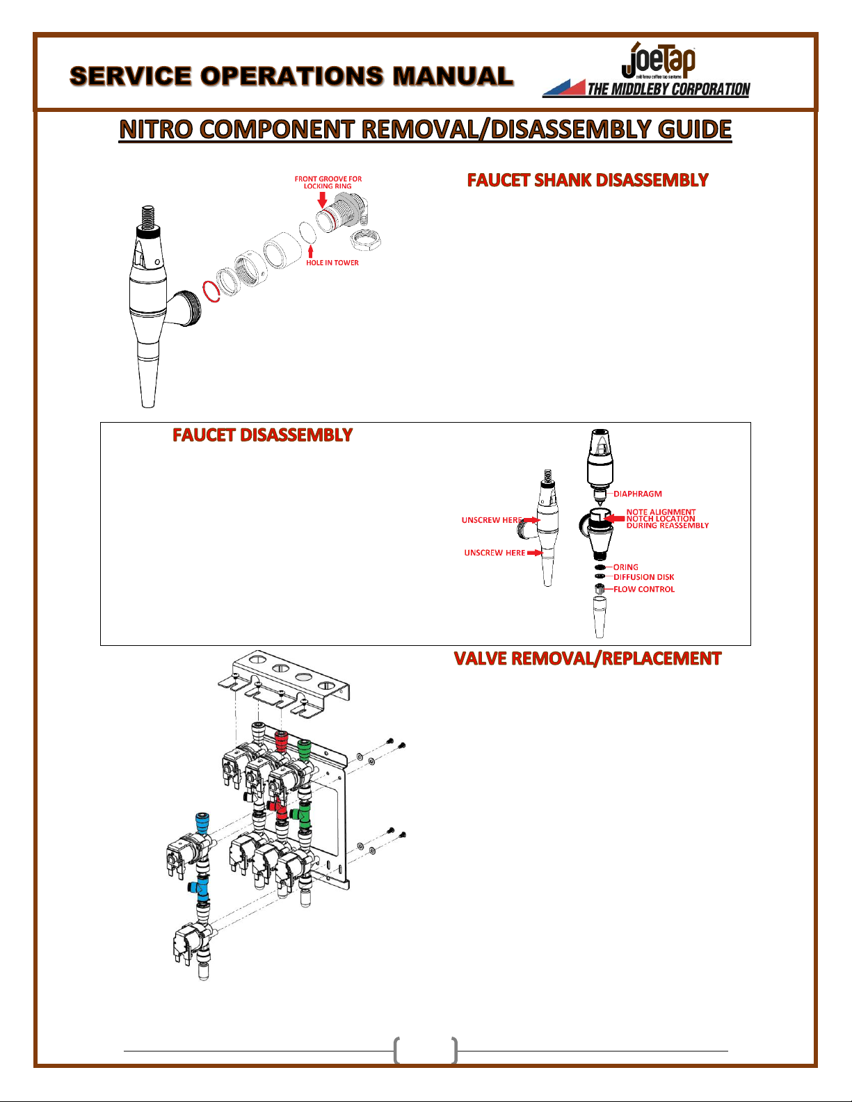
9. DISPENSING FAUCET (X4)
LOCATION: TOP OF DISPENSING TOWER
A manually operated lever utilized for dispensing of product. It is important that the lever is pulled to a completely horizontal position for proper
dispensing. The faucet is serviceable with available internal components.

4
NITROGEN CONTROL BOX/TOWER OPERATIONS
ILLUMINATED BUTTON –NITRO ACTIVATED
Nitrogen Control Solenoid status: OPEN –NO VOLTAGE PRESENT
Nitrogen Vent Solenoid status: CLOSED –NO VOLTAGE PRESENT
Nitrogen pressure from the Infusion Regulator enters the Normally
Open N2 Control solenoid valve and allowed to pass through. The
N2 Vent Solenoid is closed, channeling the Nitrogen Gas to the
Infusion Chamber.
NON-ILLUMINATED BUTTON –NITRO DEACTIVATED
Nitrogen Control Solenoid status: CLOSED –24VDC PRESENT
Nitrogen Vent Solenoid status: TEMPORARILY OPEN –24VDC
PRESENT (2 seconds only)
When a Tower Button is switched from ILLUMINATED to NON-
ILLUMINATED, the Nitrogen Control solenoid will activate and close
the nitrogen supply to the Infusion Chamber. The Timer relay in the
Control Box will send 24 VDC to the Vent Solenoid for 2 seconds to
purge static nitrogen pressure from the supply line to the infusion
chamber. After 2 seconds the Vent Solenoid will close.
TIMER RELAYS
The Timer Relays located inside the Nitrogen Control Module
provide a 2 second limit to voltage applied to the Vent
solenoid. When a Tower Button is switched from
ILLUMINATED to NON-ILLUMINATED, a constant supply of
24VDC is sent the to the input of the Timer Relay. The
resistor placed on the Timer Relay load circuit will allow only
2 seconds of power to be applied to the valve.
TO TROUBLESHOOT: Verify the corresponding Tower button
is NON-ILLUMINATED and measure the ‘+’ terminal (YELLOW
WIRE) on the Timer Relay for 24VDC. If voltage is present,
measure voltage at the ‘LOAD’ terminal (BROWN WIRE)
while cycling the Tower Button between ILLUMINATED TO
NON-ILLUMINATED. Verify the presence of 24VDC for 2
seconds only when the Tower Button switches to NON-
ILLUMINATED.

5
NITROGEN FLOW AND COFFEE INTERACTION
A. Incoming N2 pressure (30 PSI) from the
Nitrogen Generator (or Gas Cylinder) is
directed into each product keg, displacing
the liquid. Product is channeled out of the
keg and through an in-line filter into the
base of the infusion chamber located inside
the tower assembly.
B. Nitrogen flow into the infusion chamber is
controlled by the N2 Control Solenoid as
previously discussed. 12 PSI of Nitrogen, set
via the Infusion Regulators on the front of
the N2 Control Module, is directed into the
flow of liquid passing through the
midsection of the infusion chamber and
absorbed into the liquid.
C. The Nitrogen infused liquid will be pushed
through the system by 30 PSI of N2 Supply
pressure.
D. When the tap is opened, Nitrogen infused
liquid will flow past the diaphragm and
through the Diffusion Disk located in the
nozzle. The Diffusion Disk is critical to the
‘Cascading’ process once the beverage has
been dispensed into the cup.
UNWANTED NITROGEN INFUSION:
If Nitrogen gas is present on beverages designated
as Non-nitro (non-illuminated button), the volume
of unwanted nitrogen will help in determining the
nature of the issue. Verify that operating pressures
at the Primary N2 Regulator (30psi) and Infusion
Regulators (12psi) are within specification. Slight
modifications to the Infusion Regulator pressures
can mitigate unwanted N2 infusion when switching
from Nitro to Non-nitro beverages. If unwanted N2
remains, investigate the items to the right based
on the levels of unwanted nitrogen.

6
A: OUTPUT PRESSURE FROM NITROGEN SOURCE (N2
GENERATOR OR COMPRESSED GAS CYLINDER)
B: NITROGEN INFUSION PRESSURE
C: PRODUCT OUTPUT
*Please note that the Nitrogen Control components have been removed
from the diagram for simplification. The calibration guidelines below
assume that the system is clean and all components are working
properly.
A: Nitrogen Supply Pressure (30PSI RECOMMENDED)
This setting should be considered a baseline as it affects all 4 product
kegs. Because this pressure dictates the amount of pressure that will
displace, or ‘push’, product from the keg, higher pressure settings will
accelerate the flow of product through the infusion chamber, creating
higher vacuum pressures and increased agitation. Higher pressures will
INCREASE the level of N2 froth in the beverage and contribute to N2
‘carryover’ when switching from Nitro infused beverages to non-nitro
beverages.
B: Infusion Pressure
These settings are independently controlled for each tap and should be the primary adjustment utilized for determining the
level of N2 ‘froth’ for finished products. Once the Nitrogen supply pressure (A) has been set, adjust the Infusion pressure
regulators until the optimal level of froth has been achieved for each product tap. Increasing the Infusion Pressure will
INCREASE the level of froth in the beverage. 12 PSI is the factory setting, but slight adjustments may be necessary to account
for conditions specific to the site such as altitude or type of product being dispensed. Products that do not contain oil, such as
tea or lemonade, may need HIGHER infusion pressures to achieve optimal results.
C: Product output
The product output is used to determine needed pressure adjustments. It is very important that the Tap Handles are pulled all
the way downward to a horizontal position when dispensing beverages. Failure to do so will impact the level of N2 infusion in
the finished product.
NITROGEN CARRYOVER: After a Nitrogen infused beverage is dispensed, a small amount of infused product becomes trapped
between the infusion chamber and the tap. When the tap is switched to pour a non-nitro beverage, the trace amounts of
Nitrogen infused liquid in the product line are incorporated into the non-nitro beverage. This phenomenon is most noticeable in
coffee-based beverages due to its dark coloring. To mitigate this, lower the infusion pressure (B) for the specific tap until a
balance is reached between having acceptable levels of nitrogen present for infused beverages with a minimum amount of N2
carryover when switched to non-nitro beverages.

7
NO PRODUCT POUR –ALL FAUCETS
•No Nitrogen pressure from Nitrogen
Generator or Compressed Gas Cylinder
NO PRODUCT POUR –SINGLE FAUCET
•No product in keg (Opening faucet will
dispense compressed gas only)
•Improperly connected or faulty GAS/LIQUID
connectors at product keg
•In-line product filter completely clogged
•Diffusion Disk completely clogged
•Clogged pick-up tube in keg
NITRO POUR ONLY –ALL FAUCETS
•Faulty Power Supply or poor Power Supply
connection at N2 Control Module
•Primary Regulator set too high
•All Product Kegs have been connected to N2
pressure for more than 48 hours
NITRO POUR ONLY –SINGLE FAUCET
•Faulty N2 Control Solenoid or bad wiring
connection
•Partially clogged Diffusion disk in Nozzle
•N2 infused product in keg
•Leak in N2 supply tubing to tower
•Leaking N2 Vent Solenoid
•Faulty Nitro Select Button at Tower
•Product in keg is very low or has been
exposed to N2 pressure for more than 48
hours
NON-NITRO POUR ONLY –SINGLE FAUCET
•Faulty Nitro Select Button at Tower
•Faulty Infusion Regulator
•Physical blockage of N2 Supply line
•N2 ball valve closed
•Missing restrictor disk in Nozzle
NITRO CARRYOVER WHEN SWITCHING
FROM NITRO POUR TO NON-NITRO POUR
•Infusion Regulator set too high
•Primary Regulator set too high
•Faulty N2 Vent Solenoid or bad wiring
connection
•Faulty Timer Relay
•Product in keg is very low or has been
exposed to N2 pressure for more than 48
hours

8

9
•Disconnect BLACK/LIQUID Ball Lock Connector
from Product Tank.
•Turn off N2 supply valve at base of Tower
•Open faucet to relieve pressure from line
•Remove Faucet by rotating Faucet Collar clockwise
with faucet wrench
•Remove Tower cap and rest it on a Faucet handle
that is not being removed
•Remove Locknut at rear of Shank
•Push shank forward far enough to remove locking
collar at front of Shank
•Slide Shank hardware off front of shank
•Disconnect BLACK/LIQUID Ball Lock Connector
from Product Tank.
•Turn off N2 supply valve at base of Tower
•Open faucet to relieve pressure from line
•Unscrew Faucet lever and nozzle as indicated
•Replace Diaphragm, O-ring and Diffusion Disk
•Reassemble in reverse order, noting the location
of the alignment notch. The Faucet lever will only
face one direction, with the handle tilting forward
•Unplug Power Supply from rear of Control Box
•Turn off Nitrogen supply to Control Box
•Remove Control Box cover
•Remove the 8 red locking clips at the N2
Input/outputs. Four clips at top of valve
assemblies (input) and 4 clips at the tee fittings
between the two valves (output)
•Remove colored N2 supply lines at top of valve
assemblies and at output tees
•Remove wiring from all solenoids. Wires are
labelled, but make note of locations
•Remove heat-sink screws from top solenoids
•Remove 4 screws from solenoid mounting plate
and remove mounting plate from Control Box
•Remove 4 screws from rear of Mounting Plate
securing Valve Assembly
•Replace defective Valve as needed and reassemble
in reverse order

10
Factory Temperature Setting: 38°F
PRIMARY COOLING COMPONENTS
DESCRIPTION
FUNCTION
EVAPORATOR FAN
Provides air circulation for refrigerator interior. *NOTE* will not operate when door is open or if
the compressor is not actively cooling. Engage door switch to test fan.
THERMISTOR
Measures air temperature of refrigerator interior. Monitored through UI Board.
UI BOARD
User Interface for refrigerator operations. Will display temperature status and allow for
temperature adjustment as well as defrost operations.
MAIN CONTROL BOARD
Primary controller of cooling components including compressor and fan operations.
DOOR SWITCH
Provides status of door (OPEN/CLOSED) for Main Control Board.
INVERTER
Internal capacitors for Compressor operations. Allows for 120V or 208/240V operations
CONDENSER FAN
Dissipates heat from condenser coil
REFRIGERATOR SELF DIAGNOSTIC TEST
Within the first 10 minutes of plugging the unit in, press and hold the “+” icon until ‘Ct’ is displayed and then press and hold the ‘LIGHTBULB’ icon for 3
seconds. All sections of the 7-segment LED on the UI Board should illuminate for 3 seconds. The diagnostic test will take a few minutes to complete.
ERROR CODE
DESCRIPTION
ACTION
‘E1’
NON-FUNCTIONING THERMISTOR
REPLACE THERMISTOR
‘EP’
EPROM FAILURE
REPLACE MAIN CONTROL BOARD
‘BR’
MAIN BOARD FAILURE
REPLACE MAIN CONTROL BOARD

11
(FACTORY SETTINGS SHOWN)

12
THERMISTOR RESISTANCE KEY

13
**DISCONNECT UNIT FROM POWER**
REMOVE SCREWS SECURING THE LOWER
PANEL FROM REAR OF UNIT.
REMOVE SCREW ON RIGHT SIDE OF
INVERTER, THEN PUSH THE LOCKING TAB
TOWARD FRONT OF COOLER TO RELEASE
INVERTER COVER.
REMOVE SCREW FROM WIRE STRAIN
RELIEF BLOCK.
USING NEEDLE NOSED PLIERS, REMOVE
THE BLACK (POWER) AND WHITE
(NEUTRAL) WIRES FROM THE INVERTER.
INSERT TEST A LEAD FROM A MULTI METER
INTO EACH OF THE WIRES. RECONNECT
SYSTEM TO POWER AND VERIFY 120VAC IS
PRESENT. IF NO VOLTAGE PRESENT, THEN
THERE IS A CONTINUITY ISSUE OR NO
SOURCE VOLTAGE.

14
**DISCONNECT UNIT FROM POWER**
UNPLUG BLUE WIRE FROM INVERTER BY
PRESSING TAB TO RELEASE IT FROM
SOCKET.
RECONNECT UNIT TO POWER AND VERIFY
THAT THE COMPRESSOR OPERATION
INDICATOR IS LIT ON THE UI BOARD. IF LIT,
MEASURE VOLTAGE FROM BLUE WIRE TO
CHASSIS GROUND. IF NO VOLTAGE IS
PRESENT, REPLACE THE MAIN CONTROL
BOARD AT FRONT OF UNIT. IF VOLTAGE IS
PRESENT, PROCEED TO NEXT STEP.
**DISCONNECT UNIT FROM POWER**
DISCONNECT GROUND WIRE AND REMOVE
THE TWO SCREWS AS INDICATED. PULL THE
BASE OF THE INVERTER AWAY FROM THE
COMPRESSOR, ROTATING IT UPWARDS FOR
REMOVAL.
DISCONNECT GROUND WIRE AND
COMPRESSOR POWER CONNECTION.
UTILIZE A ROCKING MOTION TO REMOVE
COMPRESSOR POWER CONNECTOR.
RECONNECT WIRING TO THE INVERTER AS
SHOWN. RECONNECT UNIT TO POWER.

15
MEASURE VOLTAGE AT EACH OF THE THREE
OUTPUTS ON THE COMPRESSOR
CONNECTOR. ALL THREE SHOULD MEASURE
APPROXIMATELY 120VAC. INSUFFICIENT
VOLTAGE AT ANY OF THESE OUTPUTS
INDICATES THE INVERTER NEEDS
REPLACEMENT. PROPER VOLTAGE
INDICATES THE COMPRESSOR HAS FAILED.
INSTALL REPLACEMENT INVERTER BY REVERSING THE REMOVAL STEPS OUTLINED ABOVE. TEST
COMPRESSOR OPERATIONS ONCE REPLACEMENT IS COMPLETE.
COMPRESSOR OPERATIONS/DIAGNOSTIC GUIDE

16
**DISCONNECT UNIT FROM POWER**
PEEL ADHESIVE OVERLAY FROM UI MOUNTING
BRACKET.
REMOVE BOTH UI MOUNTING BRACKET SCREWS.
DISCONNECT WIRING HARNESS FROM UI BOARD
AND DISCARD BOARD/BRACKET ASSEMBLY.
MAKING SURE THAT THE MOUNTING HOLES AND
DISPLAY ARE PROPERLY ALIGNED, SNAP THE NEW
UI BOARD INTO NEW MOUNTING BRACKET.
PEEL AWAY THE ADHESIVE SEAL COVER TO
EXPOSE THE FOAM INSULATION GASKET. TAKE
CARE TO NOT TOUCH THE GASKET ONCE THE
COVER HAS BEEN REMOVED.

17
THOROUGHLY CLEAN THE STAINLESS STEEL
MOUNTING SURFACE FOR THE OF THE UI
BRACKET WITH ALCOHOL IF POSSIBLE.
RECONNECT THE UI BOARD TO THE WIRING
HARNESS. ENSURE THE MOUNTING HOLES ARE
ALIGNED WITH STUDS AND ADHERE THE
MOUNTING BRACKET TO THE COOLER.
SCREW THE MOUNTING BRACKET IN PLACE.
PEEL ADHESIVE BACKER FROM NEW OVERLAY
AND APPLY IT TO THE MOUNTING BRACKET.
PROCESS COMPLETE
**DISCONNECT UNIT FROM POWER**
PEEL ADHESIVE OVERLAY FROM UI MOUNTING
BRACKET.
REMOVE BOTH UI MOUNTING BRACKET SCREWS.
DISCONNECT WIRING HARNESS FROM UI BOARD
AND DISCARD OLD BRACKET ONLY. RETAIN UI
BOARD FOR REINSTALLATION.

18
CUT THE DAMAGED WIRE CONNECTOR AS CLOSE
TO THE UI CASING AS POSSIBLE. DISCARD
DAMAGED CONNECTOR.
LAY THE COOLER ON ITS BACK BEING CAREFUL
NOT TO OVER-EXTEND THE TUBING BUNDLE. ON
THE BOTTOM SURFACE OF THE OVERHANG,
PLACE A MARK 12” (CENTER) FROM THE EDGE OF
THE COOLER AND 1” FROM THE FRONT FACE OF
THE OVERHANG.
COVER THE LOWER VENT WITH A TOWEL OR
PAPER TO PREVENT INTRODUCTION OF
SHAVINGS INTO THE SYSTEM. USING A 5/8” DRILL
BIT, DRILL THROUGH THE COOLER FRAME INTO
THE UI CASING.
AFTER DEBURRING THE HOLE JUST DRILLED,
RETURN COOLER TO STANDING POSITION. PLACE
THE PROVIDED GROMMET ON TO END OF NEW
UI CABLE AS SHOWN. APPLY TAPE TO END OF
CONNECTOR TO PROTECT IT FOR NEXT STEP.
FEED THE TAPED END OF THE CONNECTOR
THROUGH THE 5/8” HOLE AND UP INTO THE UI
CASING. INSERT GROMMET INTO STAINLESS
HOLE AND SEAT IT.
REMOVE TAPE FROM CONNECTOR AND SECURE
TO UI BOARD. USE SILICONE SEALANT TO FILL
THE GAPS OF THE 5/8” HOLE.

19
MAKING SURE THAT THE MOUNTING HOLES AND
DISPLAY ARE PROPERLY ALIGNED, SNAP THE OLD
UI BOARD INTO NEW MOUNTING BRACKET.
PEEL AWAY THE ADHESIVE SEAL COVER TO
EXPOSE THE FOAM INSULATION GASKET. TAKE
CARE TO NOT TOUCH THE GASKET ONCE THE
COVER HAS BEEN REMOVED.
THOROUGHLY CLEAN THE STAINLESS STEEL
MOUNTING SURFACE FOR THE OF THE UI
BRACKET WITH ALCOHOL IF POSSIBLE.
RECONNECT THE UI BOARD TO THE WIRING
HARNESS. ENSURE THE MOUNTING HOLES ARE
ALIGNED WITH STUDS AND ADHERE THE
MOUNTING BRACKET TO THE COOLER.
SCREW THE MOUNTING BRACKET IN PLACE.
PEEL ADHESIVE BACKER FROM NEW OVERLAY
AND APPLY IT TO THE MOUNTING BRACKET.
REMOVE BOTH SCREWS SECURING THE LOWER
FRONT VENT. REMOVE VENT COVER AND SET
ASIDE

20
REMOVE 5 SCREWS SECURING LOWER
VENTILATION PANEL AT REAR OF COOLER. SET
PANEL ASIDE.
LOCATE WIRING BUNDLE INSIDE UNIT AND CUT
CABLE TIE SECURING BUNDLE TOGETHER.
LOCATE WIRE HARNESS FOR ‘DISPLAY BOARD’
AND UNPLUG OLD CABLE FROM HARNESS.
BUNDLE OLD CABLE WITH FASTENER AND TUCK
INSIDE THE UNIT OUT OF THE WAY.
FEED NEW CABLE CONNECTOR THROUGH THE
FRONT OF THE TOP MIDDLE VENT OF THE LOWER
FRONT PANEL. FEED NEW CABLE THROUGH
LOWER CHASSIS TO REAR OF UNIT.
PULL CABLE TO REAR OF UNIT UNTIL NO SLACK
REMAINS AND MOUNT FRONT VENT.
This manual suits for next models
1
Table of contents
Other JoeTap Accessories manuals