Johansson proflex 5500 User manual

User Manual
PROFLEX
VERSATILE HEADEND MODULE
Ref. 5500

5500 ProFlex
1
Contents
1. Introduction ................................................................................................................................ 2
1.1. Product description..................................................................................................... 2
1.2. Typical installation...................................................................................................... 3
1.3. Package contents ........................................................................................................ 3
1.4. Product dimensions .................................................................................................... 4
1.5. Front view of the module ........................................................................................... 5
1.6. Mounting ..................................................................................................................... 6
2. Configuring the ProFlex using the webinterface ..................................................................... 7
MINIMAL SYSTEM REQUIREMENTS ........................................................................................ 7
LOGGING IN TO THE DEVICE ................................................................................................. 7
GENERAL CONFIGURATION ................................................................................................... 8
DEVICE CONFIGURATION .................................................................................................... 11
1. Input.......................................................................................................................... 11
2. Output....................................................................................................................... 14
3. CAM........................................................................................................................... 17
3. Technical Specifications........................................................................................................... 18
4. Safety Instructions.................................................................................................................... 19
5. Conditions of warranty ............................................................................................................ 20
No part of this manual may be copied, reproduced, transmitted, transcribed or
translated into any language without permission.
Unitron reserves the right to change the specifications of the hardware and software
described in these manuals at any time.
Unitron cannot be held liable for any damages resulting from the use of this
product. Specifications are subject to change without notice. 03/17
©Unitron - Frankrijklaan 27 - B-8970 Poperinge - Belgium
T+32 57 33 33 63 F+32 57 33 45 24
email sales@unitrongroup.com
www.unitrongroup.com

5500 ProFlex
2
1. INTRODUCTION
1.1. Product description
The ProFlex satellite module has 4 inputs allowing the reception of 4 different
satellite bands per module. Because the module has 8 satellite tuners and a built-in
multiswitch, reception of 8 different transponders coming from any of the 4 input
satellite bands is possible.
Depending on the type of configuration, up to 4 DVB-T/C multiplexes, 4 MPTS or 64
STPS streams can be distributed per module, offering you one of the most flexible
and cost-efficient solutions available on the market. Other benefits include:
- versatile: one module for multiple applications
- flexible: tailor-made configuration
- future proof: configuration upgradable
- scalable: features upgradable
- feature activation can be time based
The ProFlex should be slid in a 19 inch DMH rack (Ref. 5065ETH).

5500 ProFlex
3
1.2. Typical installation
The ProFlex can be used to provide high quality satellite television in a wide range of
projects, both in the hospitality as in the residential market. Typical buildings or
infrastructures where the ProFlex can be used include, but are not limited to:
- Large and small hotels, hostels, bed and breakfasts, holiday parks
- Hospitals, resthomes, prisons
- Large and small multi-dwelling units with an international public, settlements
- Maritime infrastructure such as boats, yachts, barges
1.3. Package contents
- 1 x ProFlex (ref. 5500)
- 2 x DC banana bridges
- 5 x 75 Ohm terminators
- 4 x RF bridges
- 1 x coax cable 125mm
- 1 x ethernet patch cable 1000mm

5500 ProFlex
4
1.4. Product dimensions

5500 ProFlex
5
1.5. Front view of the module

5500 ProFlex
6
1.6. Mounting
Proper installation is critical to system performance. It is particularly important to
install the ProFlex correctly in order to receive optimal signal quality.
- Install the ProFlex in a well ventilated and cool room. In case the ambient
temperature of the room is higher than 30°C (or 91°F), the ProFlex must be
used in combination with a fan unit (Ref. 5062ETH).
- Slide the ProFlex in a 19 inch DMH rack (Ref. 5065ETH). screw 4 bolts in the
front plate of the ProFlex to secure it to the DMH rack.
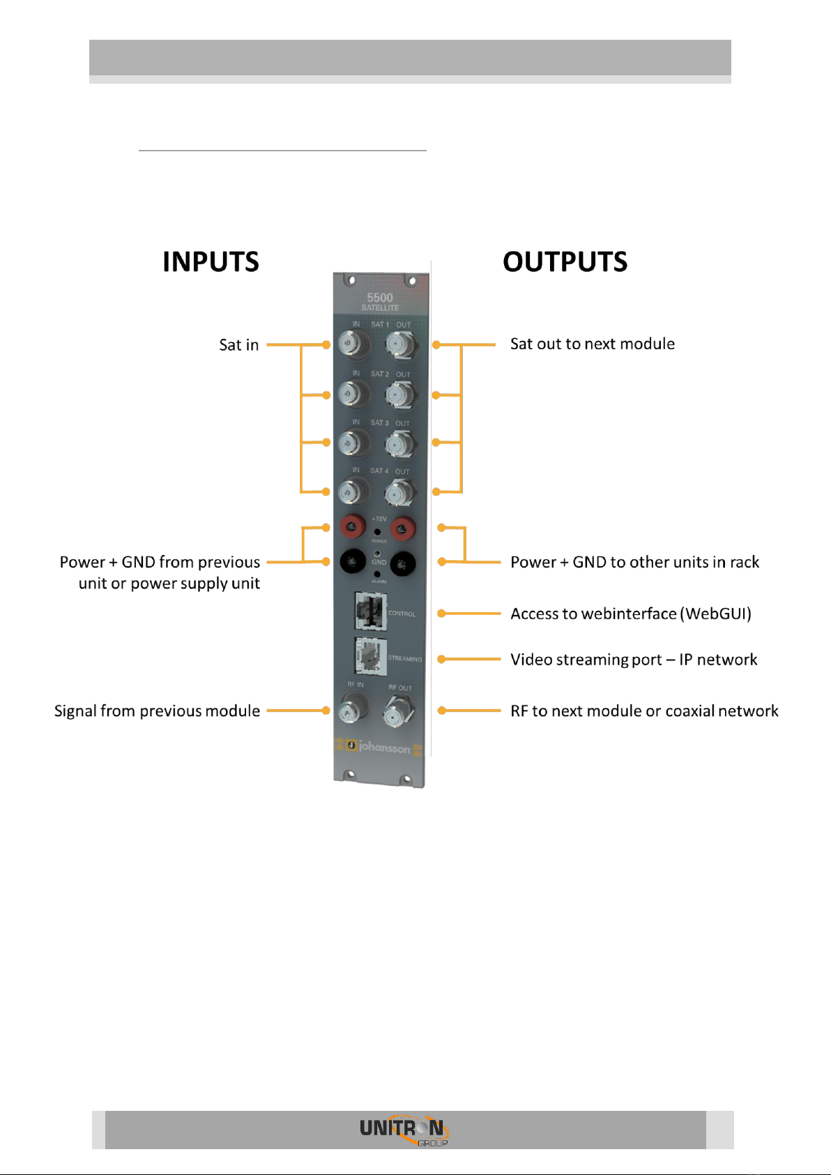
- Plug the 4 satellite cables in the Satellite in ports. If applicable, loop the
satellite signal through to the next module using the RF bridges. If not
applicable, insert a 75 Ohm terminator in each Satellite out port.
- If the ProFlex should receive RF signal from a previous module in the rack,
plug the 125mm coaxial cable in the RF in port.
- If the ProFlex is configured to read CAM cards, insert 1 or 2 CAM cards* and
smart cards* in the slots on the backside of the ProFlex. (*Not included with
the ProFlex).
- Depending on your video communication network: If video communication is
over IP network: plug an Ethernet cable in the streaming port and insert a 75
Ohm terminator in the RF out port. If video communication is over coaxial
network: insert a coaxial cable in the RF out port.
- Connect the ProFlex to the power supply unit (Ref. 5051ETH or 5051UKETH)
(power + GND) using the DC banana bridges. If applicable, also connect the
ProFlex to the next module in the rack, making sure they are powered as well.
Once it is powered, a RED LED above the control port will start blinking. When
the LED stops blinking and turns BLUE, the module is completely booted and
ready for configuration. This will take approximately 4 minutes.
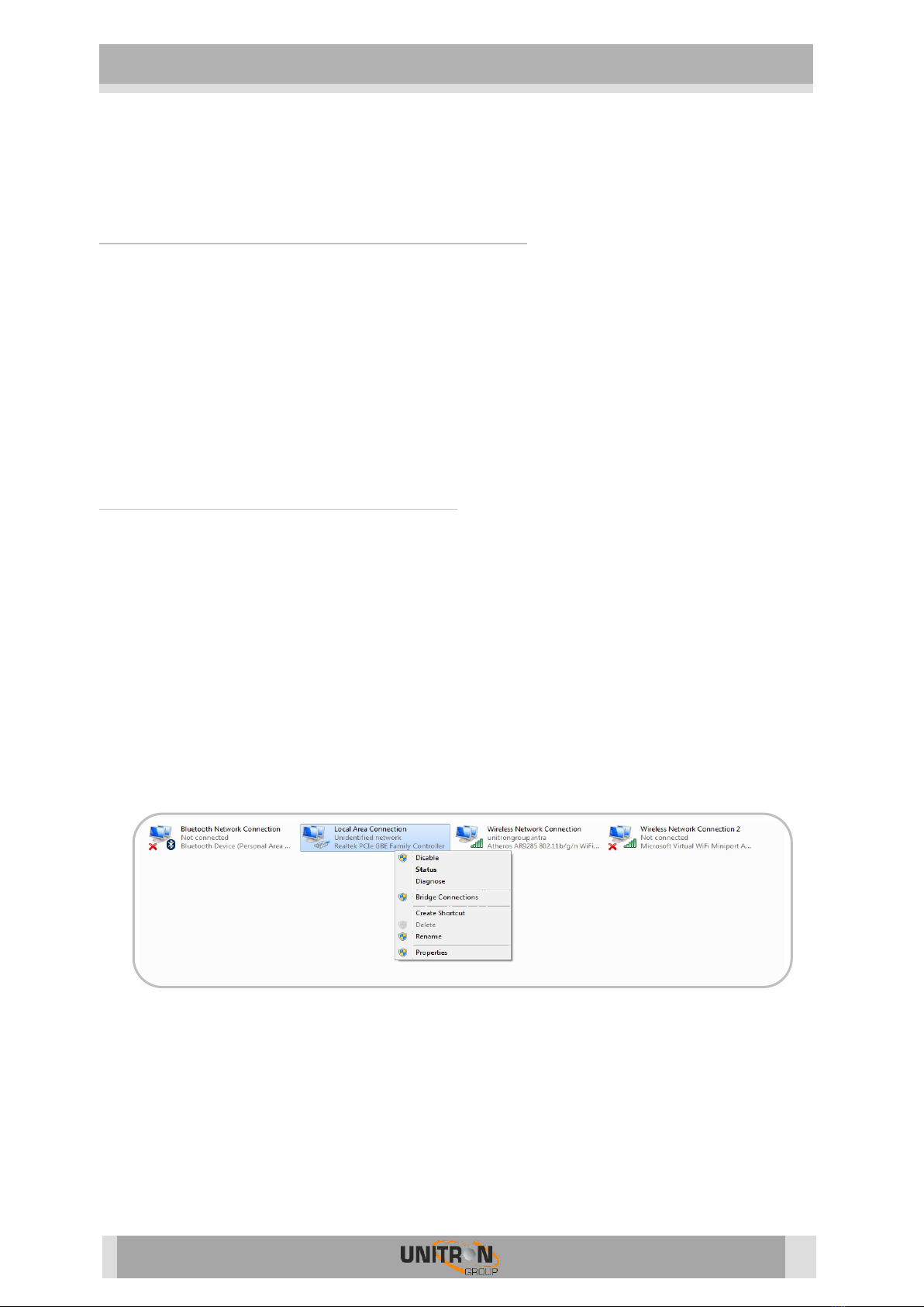
- For configuration of the module, plug one end of the Ethernet cable in the
control port, and the other end in a computer (to access the webinterface) or in
a remote control unit (Ref. 5950) (to remotely access the Universal User
Interface).
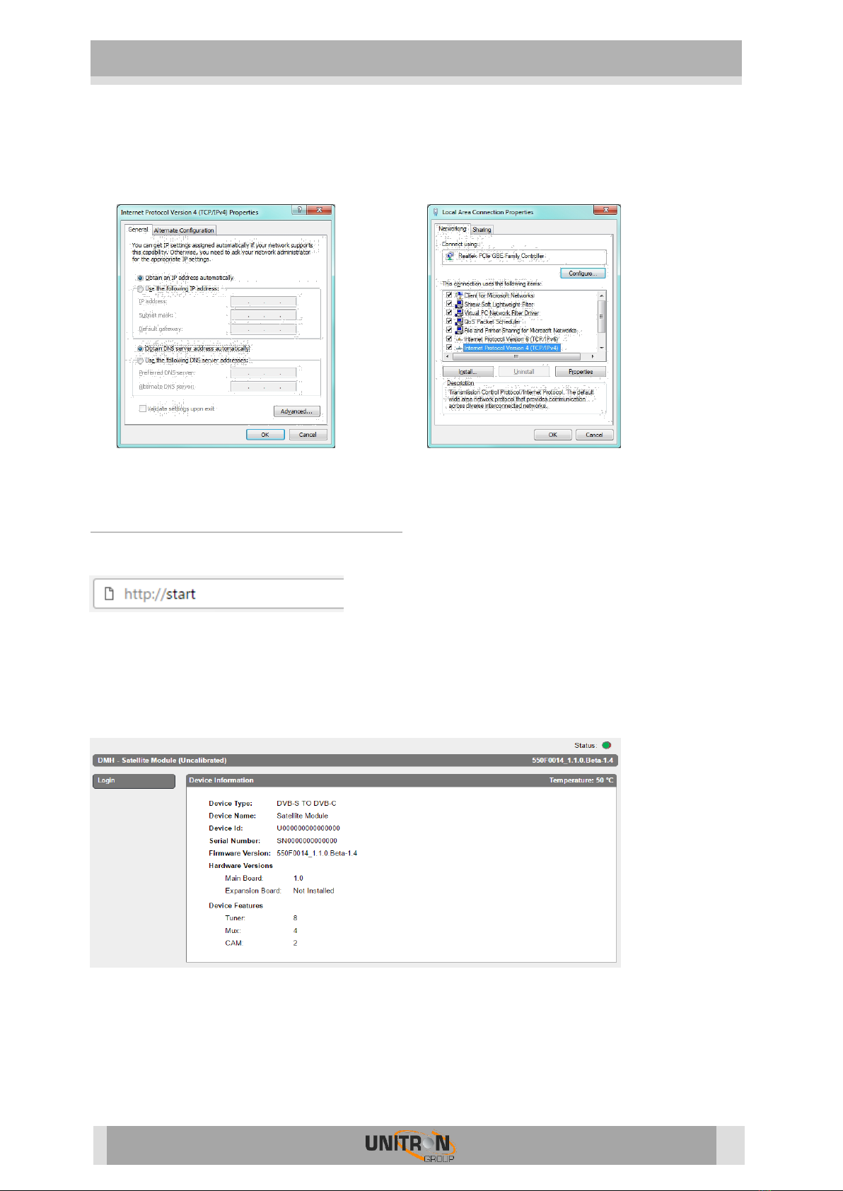
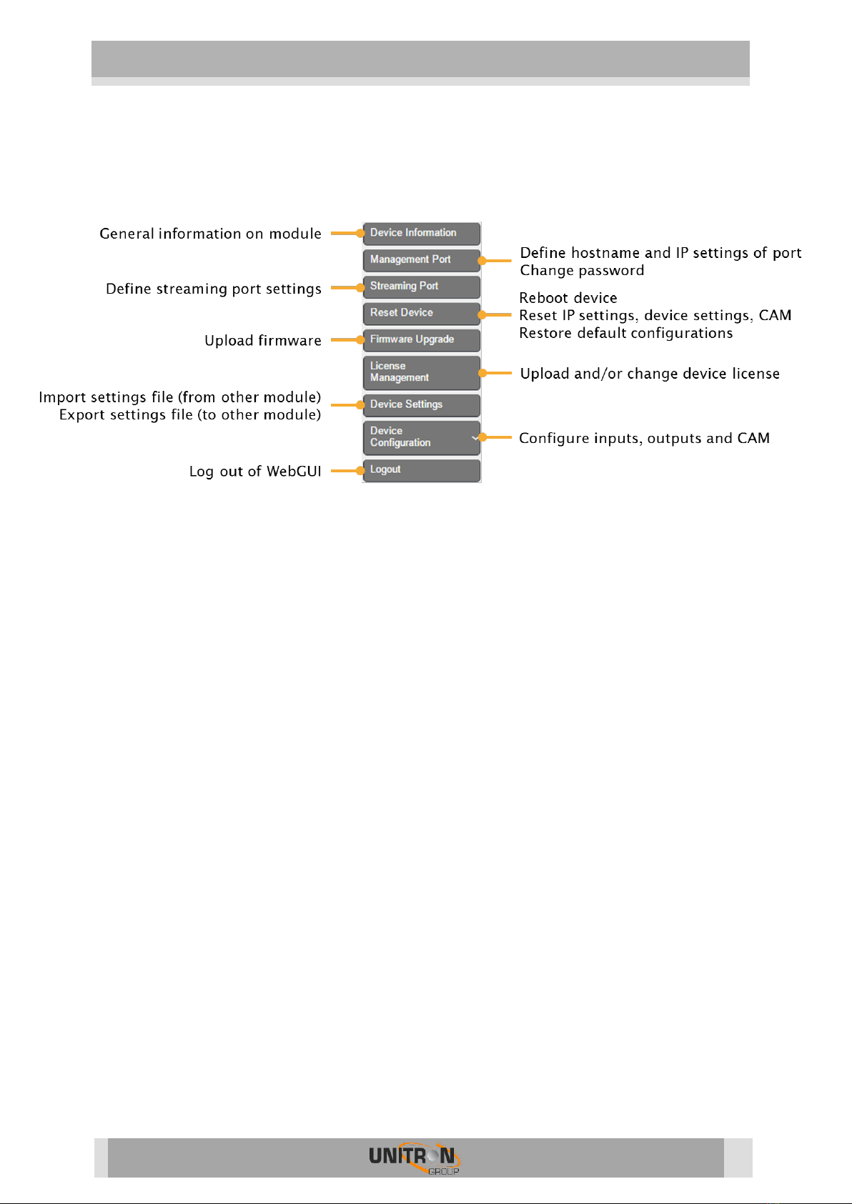
- More information about configuration of the ProFlex module can be found in
the next section

5500 ProFlex
7
2. CONFIGURING THE PROFLEX USING THE
WEBINTERFACE
MINIMAL SYSTEM REQUIREMENTS
The WebGUI is supported by the following web browsers:
- Google Chrome
- Mozilla Firefox
- Internet Explorer
- Safari
Make sure to use the most recent version of the browser. When using a different
browser, we cannot guarantee a correct functioning of the interface.
LOGGING IN TO THE DEVICE
To connect the module to your computer, plug one end of the Ethernet cable in the
control port, and the other end in a computer. Once the ProFlex is powered and fully
booted, the module is reachable and ready to be configured.
- The module will obtain an IP address from your PC, this will take a little while.
- For this operation to work, it is important that the PC is NOT set with a
manual IP address!
oSet the adapter to obtain an automatic IP address as explained in the
following procedure (for Microsoft Windows7®)
oNavigate to the Control Panel (Start Control Panel).
oEnter the Network and Sharing Center and go to the Adapter Settings
oRight-click on the Local Area Connection and choose Properties.

5500 ProFlex
8
oDouble click on Internet Protocol Version 4 (TCP/IPv4) to enter the IP
settings of your adapter.
oMake sure the ‘Obtain an IP address automatically’ checkbox is
selected.
oClick OK to save the settings.
GENERAL CONFIGURATION
- Open your network browser, and go to:
- The landing page with information about the device will appear. On this screen,
you see information about the device type, name, ID, serial number, firmware
version, hardware version and device features. In the top right corner, you will
see the device status. If the status “LED” is green, there are no alarms. When
you move your cursor over the status “LED”, the alarm status will appear.

5500 ProFlex
9
- By clicking on login, you can log in to the module. Use the password “admin”.
! change the password as soon as you log in to the module via Management Port”!
- After logging in, the Device information window will appear again. The menu
structure of the web interface can be found in the left column. In the picture
below, the different functionalities of the different menu buttons are described.
- The following actions are critical for optimal system performance:
Management port:
oDefine the hostname and IP settings of your management port:
Here you can configure the hostname of the module. This name
can be used to access the module by simply typing it into your
browser as the address and surf to it. This is more convenient
than using the IP address.
oChange your password to secure your module for unauthorized users
Streaming port:
oDefine the IP settings of your streaming port.
oSet Time-to-Live according to your network needs (default is 64)
oSet Encapsulation to UDP or RTP
Reset device:
oIf it is at issue, go to the Reset Device tab to reboot your ProFlex. Via
this tab you can also reset certain settings or restore the default
configurations of your ProFlex. All settings can be reset to default by
means of a factory reset.
oThe ProFlex can also be manually reset. This can be done by inserting a
pin (e.g. a paperclip) in the small opening in the front plate of the
ProFlex right above the letters “GND” (between the power and alarm
LEDs).
By pressing this button less than 2 seconds (LED above
management port will turn RED), the device will reboot
By pressing this button longer than 5 seconds (LED above
management port will blink GREEN), the device will reboot, the IP
settings will be reset and the password will be reset to the
default, i.e. “admin”.

5500 ProFlex
10
Firmware Upgrade:
oClick on the BROWSE button, and open the upgrade file. Click UPLOAD to
send the file to the device, this will install the new firmware on the
device.
License management:
oFor first configuration, the device license is already set and should not
be altered.
oFor a license upgrade, first upload the license file* and then activate the
device license via “Activate Device License” and press Apply. Finally,
reboot the device to make sure the firmware upgrade succeeds.
* the procedure to obtain a new license file is to send your current license identifier (LID) to
UnitronGroup and request for a new configuration according to your needs
Device Settings:
oGo to this tab if you want to import a settings file from another module
(click on choose file and select the .exp file on your computer), or
export a settings file (so you can later upload it to another module).
oThis tab can also be used to store and restore the device settings
Device configuration
oThis action is discussed below
Logout:
oWhen you are finished configuring the ProFlex, click logout to secure
the web interface for unauthorized users.

5500 ProFlex
11
DEVICE CONFIGURATION
It is of utmost importance that your device is configured in a right way in order to make the
ProFlex installation successful. To do so, follow the below mentioned steps carefully.
1. Input
1.1 Define the LNB settings (INPUT > LNB > INPUT 1-4)
oInput: Sequence number of the input (also indicated on the front
of the actual module)
oLabel: custom label for each input (e.g. VLow, or ASTRA
19.2VLow, …)
oVoltage: The LNB voltage to select the polarization
13V: Vertical polarization
18V: Horizontal polarization
oTone: LNB tone to select low/high band
ON: high band
OFF: low band
oDiSEqC®: control of a DiSEqC® switch (A/B/C/D)
oBand: Satellite band
Ku-band
C-band
oExtended Voltage: Add 1V to the LNB voltage to compensate the
cable losses for long coaxial cables.
oEnable: do not forget to enable the LNB input, this is disabled by
default)
oPress APPLY to confirm the parameters.

5500 ProFlex
12
1.2 Define the settings for each of the 8 tuners (INPUT > TUNER >
TUNER 1-8)
oInput: this refers to the LNB inputs; make sure the transponder
frequencies you choose correspond to the right polarity of the LNB
inputs
oFrequency: choose the frequency of the transponder you want to
receive
oBaud Rate: choose the baud rate of the transponder signal you want to
receive
oModulation: choose between DVB-S and DVB-S2
oEnable: click the tick box to enable the tuner (this is disabled by
default)
oCheck the lock status, signal level, signal quality and signal to Noise in
the top right of the window to see if the tuner locks on the selected
transponder
oPress APPLY to confirm the parameters.
oThe module will now set the tuner to this frequency. Wait until the
correct parameters are loaded. When the tuner is able to lock on
the frequency, the services status from this transponder will be
shown in the top right corner.

5500 ProFlex
13
1.3 Check for each tuner the configuration of your streams (INPUT >
STREAM > STREAM 1-8)
oThe streams will show you which services are included in each of the
tuned transponders.
oA lot of details of each service can be found here.

5500 ProFlex
14
2. Output
2.1 Set all the MPTS* (OUTPUT > MPTS > MPTS 1-8)
oStream: choose the input stream you set in INPUT
oName: choose the name of the stream
oPath: choose the routing of the service: FTA (Free-to-Air) –CAM 1 –CAM 2
oPriority: provides the possibility to prioritize some services (e.g.
Primetime channels) to guarantee better quality on TV in case of
sporadic bandwidth overflow due to throughput limitation of the
multiplex. It is advised not to exceed 30% of total number of services to
be prioritized for each multiplex.
oEnable:
oNew SID: Change the Service Identifier to remap the SID
oLCN: Give a Logical Channel Number to order the number of channels
on the end-devices
oDefine this for each channel in the list
oPress UPDATE to confirm the parameters.
- The bitrate bar shows the current bitrate of the selected multiplex. Depending
on the model, the ProFlex disposes of 4 multiplexes. The maximum bitrate per
MUX is 30 Mbps (DVB-T) or 50 Mbps (DVB-C). It is however advisable to keep a
buffer of 4 Mbps, to prevent possible overflow (bitrate of services can fluctuate
in time). Select another multiplex by clicking on the tabs on top of the page.
* or SPTS according to the configuration of your ProFlex

5500 ProFlex
15
2.2 Define the networks (OUTPUT > NETWORK > NETWORK 1-4)
oONID: The Original_Network_ID (ONID) is defined as the “unique
identifier of a network”, check the spreadsheets on
http://www.dvbservices.com to find your correct ONID
oTSID: Choose your Transport Stream ID
oNID: Choose your Network ID
oNetwork Name: set your network name
oVersion: set the version of the network (value between 0 and 31)
oPrivate Data Specifier: choose between EACEM –ITC –NORDIG
oPress APPLY to confirm the parameters.

5500 ProFlex
16
2.3 Set all the Mux* (OUTPUT > MUX > MUX 1-4)
oFrequency(kHz): Here you can select the frequency you want to
transmit on. For DVB-T: 47000 to 862000, for DVB-C: 47000 to
1002000
oLevel(dBm): define the level of RF (between -25 to -40)
oConstellation: Choose the type of constellation you want to use.
(64QAM, 16QAM, QPSK)
oBandwidth: Choose the desired bandwidth.
oSpectral Inversion: checking this tickbox, you inverse the RF signal.
This is only needed for receivers that do not automatically detect
spectral inversion
oEnable: click the tick box to enable the tuner (this is disabled by
default)
oPress APPLY to confirm the parameters.
*or UDP according to the configuration of your ProFlex

5500 ProFlex
17
3. CAM
3.1 Set the CAM configurations for the ProFlex (CAM > CAM 1-2)
oOnly do this if you use a ProFlex module with the CAM feature
enabled
oType: To prevent network overflow, it is important to choose the type of
the CAM (this can be found on you CAM-card:
Low-speed (legacy CAM) up to 50 Mbps
High-speed (modern CAM) up to 100 Mbps
oWatchdog: The watchdog monitors the scrambling status of all services
going through the CAM. In case one or more service sare no longer
descrambled, the watchdog will proceed to the reset of the CAM module
to try to restore the descrambling of the service(s). Activate this feature
only once all services are properly descrambled by the CAM module.
oReference Transponder: It is necessary to enable and select a reference
transponder in the CAM menu (for each CAM individually). The CAM
module needs authorization to descramble services. Select the reference
transponder with authorization information for each CAM individually.
oPress APPLY to confirm the parameters.

5500 ProFlex
18
3. TECHNICAL SPECIFICATIONS
Input
Inputs
-
4 x satellite (4 satellite bands per module)
1 IP Gigabit input (4 MPTS transport streams per
module)
Integrated
multiswitch
-
Yes, allows flexible routing of satellite programs to
multiplexes
(QAM or QOFDM)
Configuration
-
Built-in webserver or optional UUI configuration
software
Remote access
-
via RMU ref. 5950
Encoded programs
-
From all 8 tuners.
Can be routed through 1 or 2 CAMs and can be
decoded using multi-service CAMs
Output: DVB-T
DVB-T output
Mbps
Up to 31.7 / multiplex
DVB-C output
Mbps
Up to 51.3 / multiplex
IP output
-
Up to 4-MPTS transport streams in Unicast (CBR)
IPTV output
-
Up to 64-SPTS channels in Multicast (VBR)
General
Dimensions
-
5 RU x 8 TE x 367 mm
Configuration possibilities
1
-
DVB-S/S2 to DVB-C
2
-
DVB-S/S2 to DVB-T
3
-
DVB-S/S2 to IPTV
4
-
DVB-S/S2 to IP
5
-
IP to DVB-C
6
-
IP to DVB-T
Features possibilities
1
#Tuners
1 to 8
2
#Mux
1 to 4
3
#CAM
0, 1, 2
4
#SPTS
16, 32, 48, 64
5
#MPTS
1 to 4
6
#IPLOOP
0, 1 to 4

5500 ProFlex
19
4. SAFETY INSTRUCTIONS
Read these instructions carefully before connecting the unit
To avoid any risk of
overheating:
Install the unit in a well aery location and keep a minimum distance of 15 cm around the
apparatus for sufficient ventilation
Do not place any items such as newspapers, table-cloths, curtains,… on the unit that
might cover the ventilation holes.
Do not place any naked flame sources, such as lighted candles, on the apparatus
Do not install the product in a dusty place
Use the apparatus only in moderate climates (not in tropical climates)
Respect the minimum and maximum temperature specifications
To avoid any risk of electrical
shocks:
Connect apparatus only to socket with protective earth connection.
The mains plug shall remain readily operable
Pull out power plug to make the different connections of cables
To avoid electrical shock, do not open the housing of adapter.
Maintenance
Only use a dry soft cloth to clean the
cabinet.
Do not use solvent
For repairing and servicing refer to qualified
personnel.
Dispose according to your local authority’s recycling processes
Table of contents
Popular Control Unit manuals by other brands

Deditec
Deditec ETH-RELAIS-8 Hardware description

Grundfos
Grundfos CU 361 manual

KIESELMANN
KIESELMANN 567 Series Operating instruction

HYDAC International
HYDAC International FMMHP Operating and maintenance instructions

Gebwell
Gebwell G-Power 2/100 Installation and maintenance manual

Honeywell
Honeywell L4068 manual