manuals.online logo
Brands
  1. Home
  2. •
  3. Brands
  4. •
  5. John Crane
  6. •
  7. Water Pump
  8. •
  9. John Crane Metastream TSK Manual

John Crane Metastream TSK Manual

COUPLINGS TYPE TSK – TSP – TSA – TSC - TLK
Fitting, Operating and Maintenance Instructions
No. G
-
001
-
E
-
A
General Specification
The ranges of Metastream couplings covered by this manual, are designed to transmit torque
between the rotating shafts of a driving and driven machine, whilst accomodating the inevitable
lateral, angular and axial misalignment, which will exist between two coupled machines.
The usual extentof supply comprises:
•a hub for the DRIVING machine (motor) shaft
•a hub for the DRIVEN machine shaft
•a factory assembled transmission unit, comprising two packs of flexible metallic discs,each
bolted to a “guard ring” and to a common spacer (distance piece), which separates the two disc
packs, The overall length of the transmission unit issized to suitthe shaft end separation of the
coupled machines
•a set of fasteners to assemble the transmission unitto the two hub flanges.
IMPORTANT
These instructions should be read in conjunction with any application specific general arrangement
drawing which maybe supplied with the coupling.
Selection verification
Although a coupling may be correctly specified at the time of order placement, the duty conditions
can sometimes change prior to the coupling being put into service. Information is available from
John Crane to advise on the selection and limitations of their power transmission products, but the
USER is ultimately responsible for verifying the suitability of the selection for the actual service
conditions.
The coupling and its manner ofuse must conform to any legal or licensing requirements, and, where
appropriate, meetlocal health and safety requirements.
IMPORTANT: If the conditions of operations are changed without approval from John Crane, then
we would decline responsibility for anyconsequentdamage and the USER would assume all risks.
Documentation supplied with the coupling should be retained for future reference.
Unpacking and Storage
The coupling should be unpacked and examined for any signs of transit damage. Particular attention
should be paid to hub bores and spigot/recess local diameters.
If the coupling is not to be used immediately, it should be re-packed and stored in a dry place away from
directheat.
Documentation supplied with the coupling should be retained for future reference.
Installation
Prior to installing the coupling ensure that the machinery is made safe
•Remove the coupling from its packaging and carefully inspect for signs of damage. Particular attention
should be paid to the hub bores and the spigot/recess location features, which should be free from
burrs and other damage.
•Fit the Driver (1) and Driven (2) hubs to the corresponding machine shafts. Normally, John Crane
supply parallel bored and keywayed hubs, individually machined to give a light interference fit with the
associated shaft. If it is necessary to apply some heating to the hub to assist fitting, then a warm oil
bath will usually be adequate.
Hubs must be adequately supported during installation to avoid accidental damage should
they slip.
It is usual to install the hub such that the hub face and shaft end are flush, but consultthe arrangement
drawing, or other particular instructions,to check the configuration for individual designs.
Align the centre lines of the driving and driven machine shafts as follows:
•With one machine firmly bolted down, set the distance between shaft ends (DBSE) according to
drawing or catalogue dimension ‘A’
IMPORTANT: DBSE is usually measured between the inner face of the hubs and should not be
taken as the length of the transmission unit at its maximum diameter
•Align the shaft centre lines both horizontallyand vertically byaligning the hub flanges. The John Crane
coupling alignment kit and reverse peripheryprocedure allows rapid and accurate alignment of shafts.
IMPORTANT: The misalignment tolerances quoted in literature and on drawings allow for dynamic
conditions and variations. For the best service from the coupling, John Crane recommend that
installed misalignment is no more than10% ofthe maximum allowable misalignment, allowance being
made for any anticipated movements which will occur during operation (eg. thermal movements on
hut pumps).
•Check spigot and recess locations on the hubs and transmission unit for burrs or other signs of damage
and then fit the transmission unit(3) between the hubs.
THE TRANSMISSION UNIT MUST BE ADEQUATELY SUPPORTED DURING INSTALLATION
TO AVOID ACCIDENTAL DAMAGE SHOULD IT SLIP.
It may be necessary to compress the transmission unit whilst sliding it between the hubs, and facilities are
provided to make it easier:
1. on smaller units,lever slots are provided in the hub flanges
2. on larger units, including the TLK, the spacer flanges are drilled so
that the hub bolts (4) may be used to compress the transmission unit
sufficiently to clear the spigot location (see sketch).
Maximum compression ofthe gap ‘X’ should notexceed 0.8 times the
coupling maximum axial misalignement value, unless indicated
otherwise on the general arrangement drawing.
IMPORTANT: Always remove the compression bolts as soon as the transmission unit is in position
and before fully tightening the hub bolts.
Fit the hub bolts (4) (and locking washers (5) if supplied) and tighten these evenly to locate the transmission
unit, ensuring that the spigots enter their recess squarely. Boltsshould be tightened in a “diametrically
opposite” sequence to the valuesquoted in Table 1.If a general arrangement drawing issupplied with the
coupling, then torque values quoted on that drawing take precedence.
•Rotate the machinery two or three timesslowly to ensure it moves freely.
The coupling is now ready for continuous and trouble free service.
John Crane Italia SpA
Via Giotto 3
20053 Muggiò (MI)
Tel. 039-2714.1
Fax 039-2714.300
Operation
BEFORE STARTING THE MACHINERY, ENSURE THAT ALL NECESSARY SAFETY
PROCEDURES ARE BEING OBSERVED
When operated within the duty conditions for which they were designed, John Crane Metastream
flexible disc couplings will give long and trouble free service. Routine examination should include
a periodic check on the tightness of fasteners and visual inspection of transmission components
for signs offatigue or wear.
Ifthe coupled machinery isdisturbed atany time, then shaft alignment should be re-checked as a
matter of routine. Alignment checking is also recommended if a deterioration of installation
alignment during service is suspected.
Inspection and Maintenance
MAINTENANCE WORK MUST ONLY BE CARRIED OUT BY SUITABLY QUALIFIED
PERSONNEL WHEN THE EQUIPMENT IS STATIONARY AND HAS BEEN MADE SAFE
John Crane Metastream flexible power transmission couplings are designed to give long and
trouble free service if operated within the conditions for which they were specified. Failures are
rare and can generally be attributed to:-
•excessive misalignment
•severe torsional overload
In all cases of coupling failure, the cause should be identified and corrected before replacing the
coupling.
The usual mode of failure of flexible disc couplings is rupture of the flexing membranes. In such
circumstances, it is possible to repair the coupling byfitting a replacement disc pack assembly.
ATTENTION: When repairing John Crane Metastream flexible disc couplings, only John
Crane approved parts should be used.
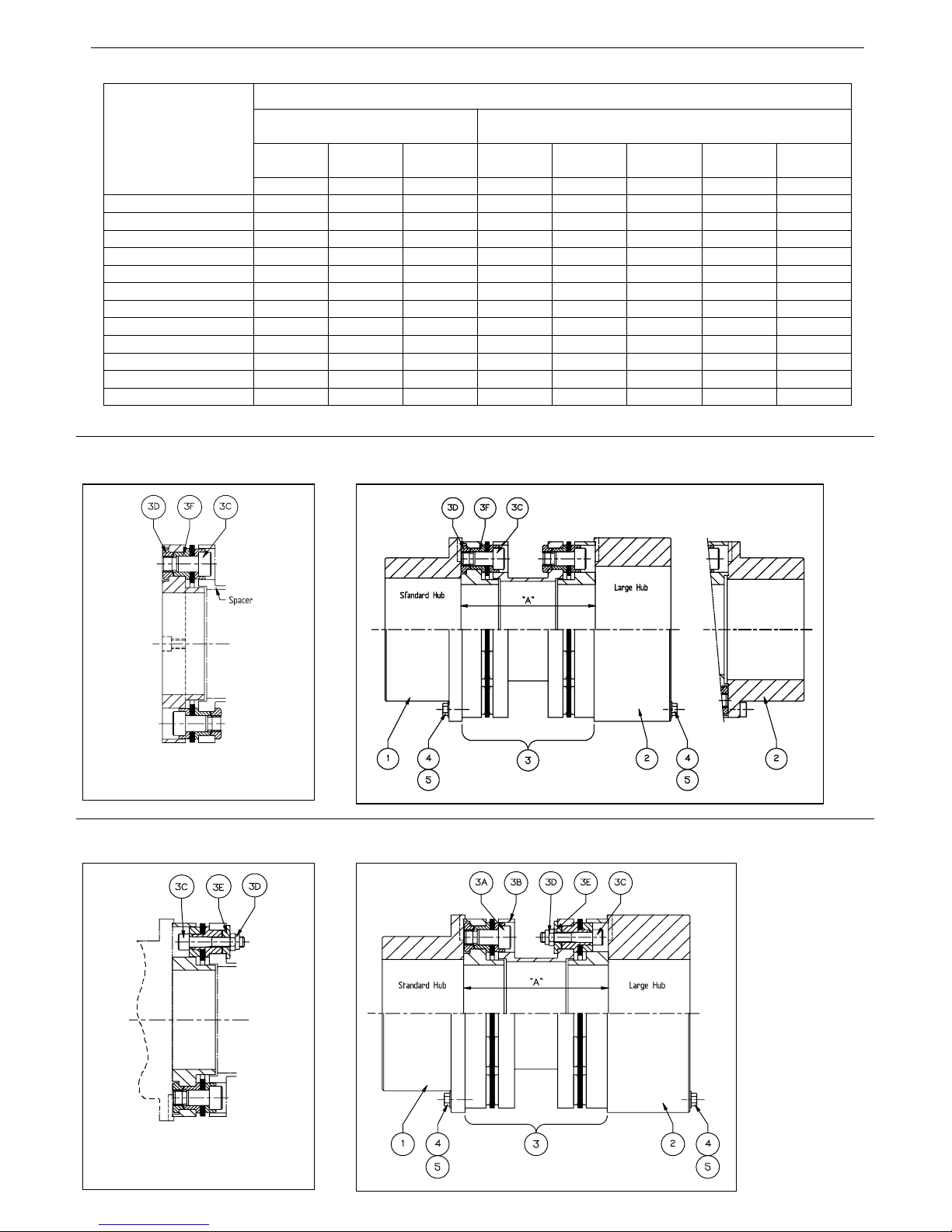
•To replace the transmission unit (3), first remove the hub bolts (4) and then withdraw the
transmission unitusing the lever slots in the hubs or compression bolt feature in the spacer as
appropriate.
TRANSMISSION UNIT MUST BE ADEQUATELY SUPPORTED DURING REMOVAL
TO AVOID ACCIDENTAL DAMAGE SHOULD IT SLIP
•Identify the bolts which connect the disc packs to the spacer piece. Slacken and remove
these drive bolts (3C) and nuts (3D) and carefully dismantle the disc pack assemblies from
the spacer piece. Do not attempt to dismantle the disc pack assemblies any further;
replacementdisc packs are always supplied complete with a new guard ring.
•Subsequent refurbishment is dependent on the type of coupling involved and the precise
configuration of the replacement membrane pack. It is recommended that BOTH membrane
packs be replaced,as failure of one inevitably results in some damage to the other.
TSP (TSA) REPLACEMENT PACK
•Complete the removal ofthe old disc packassemblies by pressing the washers(3E) out of the
holes in each spacer flange.
•Identify the fasteners which attach the disc packs to the spacer. Disassemble the loosely
assembled nuts (3D) and separate the bolts (3C)and washers (3E).
•Fit new washers (3E) into the spacer.
•Carefully press the protruding sleeves in each disc pack into the holes in the spacer flange,
taking care notto over-strain the flexible discs. Insertthe drive bolts (3C) from the guard ring
side and secure using the locknuts (3D). Tighten the locknuts evenly to the correct SPACER
BOLT tightening torque value given in Table 1.
•Complete the refurbishment of the transmission unit by replacing the second disc pack
assembly.
TSK [TSC] AND TLK REPLACEMENT PACK
•Complete the disassembly of the old disc packs by pressing the sleeves (3F) out of the
holes in each spacer flange.
•Identify the fasteners which attach the disc packs to the spacer flanges. Disassemble the
loosely assembled nuts (3D).
•With the bolts (3C) in position, carefully press on the bolt heads to push the new sleeves
into the holes in the spacer flange. Take care notto over-strain the flexible discs.
•Place a small amount of threadlocking compound (e.g. Loctite 242) on the protruding bolt
threads and then assemble the nuts(3D). Tighten these nuts evenly to the correct spacer
bolt tightening torque value given in Table 1.
•Complete the refurbishment of the transmission unit by replacing the second disc pack
assembly.
•Having rebuilt the transmission unit, it is recommended that the shaft alignment be
checked prior to re-installation.
•The refurbished transmission unit should be installed in accordance with the instructions
for fitting a new coupling.
IMPORTANT Hub bolts should be replaced every time the coupling is dismounted.
ATTENTION: REPLACEMENT OF THE DISC PACK ASSEMBLIES INEVITABLY
CHANGES THE INHERENT BALANCE OF THE TRANSMISSION UNIT. HENCE, IF A
BALANCED COUPLING NEEDS REFURBISHING, IT IS RECOMMENDED THAT A
FACTORY ASSEMBLED AND BALANCED TRANSMISSION UNIT BE FITTED TO ENSURE
FUTURE, VIBRATION FREE OPERATION. IF REPLACEMENT DISC PACK ASSEMBLIES
ARE FITTED TO A BALANCED TRANSMISSION UNIT, THEN CONSIDERATION MUST BE
GIVEN TO REBALANCING OF THE REFURBISHED TRANSMISSION UNIT OR IN-SITU
BALANCING OF THE COUPLING.
WARNING
All necessary steps have been taken to ensure, as far as is reasonably practical,
that couplings are designed and manufactured to be safe when properly used.
These instructions are, however, general and it is important that users observe all
statutory plant and other safety requirements.
All safety requirements mustbe strictly adhered to.
Ensure all precautions are taken to avoid personnel hazards.
Full machinery protection (safety guards)is ensured.
Use protective clothes.
John Crane will provide advice on the use of couplings, but the following are the sole
responsibility of the User:
•Compliance with statutory plant requirements
•Compliance with other safety requirements
•Final choice of a coupling for a particularduty
Fitting, operating and maintenance operations should be carried out by qualified,
experienced and competent people,for whom these instructions have been written.
METASTREAM COUPLING TYPE TSK, TSC, TLK GIUNTI METASTREAM TIPO TSK, TSC, TLK
METASTREAM COUPLING TYPE TSP, TSA GIUNTI METASTREAM TIPO TSP, TSA
Table 1 – STANDARD COUPLING BOLT TIGHTENING TORQUES/COPPIE DI SERRAGGIO BULLONI DI GIUNTI STANDARD
BOLT TIGHTENING TORQUES/COPPIE DI SERRAGGIO BULLONI
HUB BOLTS/BULLONI MOZZO (4) SPACER BOLTS/BULLONI SPAZIATORE (3C/3D)
FOR REFURBISHMENT/PER RIPRISTINO
TSK
TSP TSC
TSA TLK TSK TSP TSC TSA TLK
COUPLING SIZES
GIUNTO TIPO
N-m lb-ft N-m N-m N-m lb-ft lb-ft N-m
0011 0013 13 7 - 11 - 8 - -
0027 0033 25 14 - 23 9 17 7 -
0060 0075 25 14 - 47 17 35 14 -
0110 0135 25 14 - 75 31 55 26 -
0180 0230 50 26 - 130 31 95 26 -
0260 0350 25 14 - 150 58 110 41 -
0400 0500 50 26 - 205 58 150 41 -
0560 0740 50 26 - 285 145 210 125 -
0750 0930 86 63 - 380 145 280 125 -
1120 86 63 - 490 277 360 220 -
1400 86 63 86 490 - 360 - 380
1850 - - 86 ----490
(Data given on general arrangement drawings takes precedence) (I valori indicati sul disegno sono prioritari)
MozzoStandard MozzoLar
g
o
Mozzo Standard Mozzo Largo
Spaziatore
REPLACEMENT MEMBRANE PACK
SOSTITUZIONE PACCO MEMBRANA
REPLACEMENT MEMBRANE PACK
SOSTITUZIONE PACCO MEMBRANA
STORAGE AND TRANSPORTATION
METASTREAM COUPLINGS
1. INTRODUCTION
John Crane manufacture and supply Metastream couplings of the highest quality. These are
precision-made pieces of equipment, with faces within hundreds of a mm. allowance. Every care
is taken in their design, manufacture, assembly, and despatch to ensure that they are of the
highest quality, and that they reach their destination to our customer’s satisfaction.
To obtain the optimum performance from our couplings, it is important that they are both fitted
and operated correctly in line with our technical literature. It is also important that couplings are
transported stored, packaged, and handled correctly from the time of delivery to installation in the
equipment.
The following designations are used in this instruction manual to highlight instructions of particular
importance:
NOTE: Refers to special information on how to install or operate the coupling most efficiently.
ATTENTION: Refers to special information or instructions directed towards the prevention of
damage to the coupling or to the equipment involved..
Refers to mandatory instructions designed to prevent personal injury or extensive
damage to the coupling.
2. PACKAGING AND TRANSPORTATION
•John Crane chooses a level of packaging appropriate to the item, the method of
transportation, the environment, and its known destination; if this is an intermediate location
the Company must be advised in advance.
•Specialised packaging is available for particular circumstances.
ATTENTION: Metastream couplings to be transported should always be retained in their original
packaging or an equivalent.
•Equal attention to packaging is needed when transporting couplings when parts are being
returned or reconditioning is planned.
In many instances the original supply packaging is reusable, and if stored appropriately can
be used when moving used parts.
•Transported parts should always be accompanied by documentation confirming the
manufacturer, his identification code, and the reason for the supply.
It is the responsibility of the user to ensure that any parts being sent to a third party
have been appropriately decontaminated and have safe-handling instructions
externally attached to the package.
•On receipt of the package, its contents should be checked against the accompanying
documentation. Minimal disturbance should be applied, and after inspection the parts and all
relevant documentation should be replaced in the original packaging.
•If the package contains a coupling, it will also include an Instruction Manual and/or other
instructions. This information should be read thoroughly before handling the coupling. The
Instruction Manual should remain with the coupling unit until it is installed, and should then be
stored in an accessible and clean area.
•John Crane should be notified immediately if, after checking the documentation, it indicates an
item is missing, doesn’t comply, or there is concern an item has been damaged in transit.
If a part is damaged in transit, the coupling’s integrity may be affected.
ATTENTION: Any gags should be removed before the start-up.
•No sharp edges likely to cause physical injury should exist, but function or processing may
have necessitated them. Check parts before handling and either avoid risk areas, and wear
appropriate protection
3. STORAGE
•The coupling should be fitted with gags to prevent undue movement of the membranes
during transportation and installation. Even so it must be appreciated that these couplings are
high precision items and should be handled carefully to avoid shock loads. It is also
recommended that couplings are stored horizontally. They should not be stood on end.
•The coupling in its container has been carefully packed to give protection during transport
and storage for a minimum period of two years. It is recommended that the coupling is kept in
this package until it is required for installation.
•If a coupling is removed from its packaging for any reason and not installed, the coupling and
its components must be cleaned and repacked. If the time to installation is so short that
complete repackaging is not considered necessary, then the coupling should be at least kept
in its case, along with technical literature and instructions supplied, until required.
•The benefits of careful packaging are nullified if couplings are badly handled when they reach
their destination.
John Crane Italia SpA
Via Giotto, 3
20053 Muggiò (MI)
Tel. 039-2714.1
Fax 039-2714.300

This manual suits for next models

5

Popular Water Pump manuals by other brands

BLACK DECKER BXGP600PBE manual

BLACK DECKER

BLACK DECKER BXGP600PBE manual

AQUA FORTE DM-E Series manual

AQUA FORTE

AQUA FORTE DM-E Series manual

IMP PUMPS NMTD SAN MAX II 32-120 Installation and operating manual

IMP PUMPS

IMP PUMPS NMTD SAN MAX II 32-120 Installation and operating manual

Little Giant 5-ASP-LL manual

Little Giant

Little Giant 5-ASP-LL manual

AQUA FORTE Forza 5000 manual

AQUA FORTE

AQUA FORTE Forza 5000 manual

i-MO ACG Maintenance and service instructions

i-MO

i-MO ACG Maintenance and service instructions

Astral Pool A142C owner's manual

Astral Pool

Astral Pool A142C owner's manual

Little Giant PE-2.5 Series quick start guide

Little Giant

Little Giant PE-2.5 Series quick start guide

Little Giant 4-MD instruction sheet

Little Giant

Little Giant 4-MD instruction sheet

mr. steam Feel Good AromaSteam Installation, operation & maintenance manual

mr. steam

mr. steam Feel Good AromaSteam Installation, operation & maintenance manual

Flofab 880RI Series Operation, maintenance & installation manual

Flofab

Flofab 880RI Series Operation, maintenance & installation manual

Ecoflo EPP33 owner's manual

Ecoflo

Ecoflo EPP33 owner's manual

ThePondguy SuperFlo 9000 product manual

ThePondguy

ThePondguy SuperFlo 9000 product manual

aqua technix AQUA VARIO Plus Original installation and operating manual

aqua technix

aqua technix AQUA VARIO Plus Original installation and operating manual

Flofab FBV 322 Series Operation & service manual

Flofab

Flofab FBV 322 Series Operation & service manual

red lion RL-SWJ Series owner's manual

red lion

red lion RL-SWJ Series owner's manual

Ecoflo EPP33 owner's manual

Ecoflo

Ecoflo EPP33 owner's manual

Power Fist 1-1/2 in. user manual

Power Fist

Power Fist 1-1/2 in. user manual

manuals.online logo
manuals.online logoBrands
  • About & Mission
  • Contact us
  • Privacy Policy
  • Terms and Conditions

Copyright 2025 Manuals.Online. All Rights Reserved.