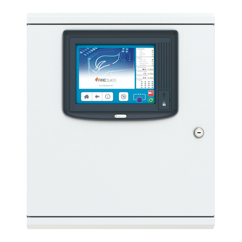
Johnson Controls NION-2C8M User manual

JCI
Intelligent Fire Integrator™
NION-2C8M
Installation & Operation Manual
Document 53346
5/5/09 Rev: A1
P/N: 53346:A1 ECN: 09-347

2NION-2C8M Installation & Operation Manual - P/N: 53346:Rev: A1 5/5/09
Fire Alarm System Limitations
While a fire alarm system may lower insurance rates, it is not a substitute for fire insurance!
An automatic fire alarm system—typically made up of smoke detec-
tors, heat detectors, manual pull stations, audible warning devices,
and a fire alarm control panel with remote notification capability—can
provide early warning of a developing fire. Such a system, however,
does not assure protection against property damage or loss of life
resulting from a fire.
The Manufacturer recommends that smoke and/or heat detectors be
located throughout a protected premise following the recommenda-
tions of the current edition of the National Fire Protection Association
Standard 72 (NFPA 72), manufacturer's recommendations, State and
local codes, and the recommendations contained in the Guide for
Proper Use of System Smoke Detectors, which is made available at
no charge to all installing dealers. These documents can be found at
http://www.systemsensor.com/html/applicat.html.
A study by the Federal Emergency Management Agency (an agency
of the United States government) indicated that smoke detectors may
not go off in as many as 35% of all fires. While fire alarm systems are
designed to provide early warning against fire, they do not guarantee
warning or protection against fire. A fire alarm system may not provide
timely or adequate warning, or simply may not function, for a variety
of reasons:
Smoke detectors may not sense fire where smoke cannot reach the
detectors such as in chimneys, in or behind walls, on roofs, or on the
other side of closed doors. Smoke detectors also may not sense a fire
on another level or floor of a building. A second-floor detector, for
example, may not sense a first-floor or basement fire.
Particles of combustion or “smoke” from a developing fire may not
reach the sensing chambers of smoke detectors because:
• Barriers such as closed or partially closed doors, walls, or chimneys
may inhibit particle or smoke flow.
• Smoke particles may become “cold,” stratify, and not reach the ceiling
or upper walls where detectors are located.
• Smoke particles may be blown away from detectors by air outlets.
• Smoke particles may be drawn into air returns before reaching the
detector.
The amount of “smoke” present may be insufficient to alarm smoke
detectors. Smoke detectors are designed to alarm at various levels of
smoke density. If such density levels are not created by a developing
fire at the location of detectors, the detectors will not go into alarm.
Smoke detectors, even when working properly, have sensing limita-
tions. Detectors that have photo-electronic sensing chambers tend to
detect smoldering fires better than flaming fires, which have little visi-
ble smoke. Detectors that have ionizing-type sensing chambers tend
to detect fast-flaming fires better than smoldering fires. Because fires
develop in different ways and are often unpredictable in their growth,
neither type of detector is necessarily best and a given type of detec-
tor may not provide adequate warning of a fire.
Smoke detectors cannot be expected to provide adequate warning of
fires caused by arson, children playing with matches (especially in
bedrooms), smoking in bed, and violent explosions (caused by escap-
ing gas, improper storage of flammable materials, etc.).
Heat detectors do not sense particles of combustion and alarm only
when heat on their sensors increases at a predetermined rate or
reaches a predetermined level. Rate-of-rise heat detectors may be
subject to reduced sensitivity over time. For this reason, the rate-of-
rise feature of each detector should be tested at least once per year
by a qualified fire protection specialist. Heat detectors are designed to
protect property, not life.
IMPORTANT! Smoke detectors must be installed in the same room
as the control panel and in rooms used by the system for the connec-
tion of alarm transmission wiring, communications, signaling, and/or
power. If detectors are not so located, a developing fire may damage
the alarm system, crippling its ability to report a fire.
Audible warning devices such as bells may not alert people if these
devices are located on the other side of closed or partly open doors or
are located on another floor of a building. Any warning device may fail
to alert people with a disability or those who have recently consumed
drugs, alcohol or medication. Please note that:
• Strobes can, under certain circumstances, cause seizures in people
with conditions such as epilepsy.
• Studies have shown that certain people, even when they hear a fire
alarm signal, do not respond or comprehend the meaning of the signal.
It is the property owner's responsibility to conduct fire drills and other
training exercise to make people aware of fire alarm signals and
instruct them on the proper reaction to alarm signals.
• In rare instances, the sounding of a warning device can cause tempo-
rary or permanent hearing loss.
A fire alarm system will not operate without any electrical power. If
AC power fails, the system will operate from standby batteries only for
a specified time and only if the batteries have been properly main-
tained and replaced regularly.
Equipment used in the system may not be technically compatible
with the control panel. It is essential to use only equipment listed for
service with your control panel.
Telephone lines needed to transmit alarm signals from a premise to a
central monitoring station may be out of service or temporarily dis-
abled. For added protection against telephone line failure, backup
radio transmission systems are recommended.
The most common cause of fire alarm malfunction is inadequate
maintenance. To keep the entire fire alarm system in excellent work-
ing order, ongoing maintenance is required per the manufacturer's
recommendations, and UL and NFPA standards. At a minimum, the
requirements of NFPA 72 shall be followed. Environments with large
amounts of dust, dirt or high air velocity require more frequent mainte-
nance. A maintenance agreement should be arranged through the
local manufacturer's representative. Maintenance should be sched-
uled monthly or as required by National and/or local fire codes and
should be performed by authorized professional fire alarm installers

3NION-2C8M Installation & Operation Manual - P/N: 53346:Rev: A1 5/5/09
Installation Precautions
Adherence to the following will aid in problem-free installation with long-term reliability:
WARNING - Several different sources of power can be connected to
the fire alarm control panel. Disconnect all sources of power before
servicing. The control unit and associated equipment may be dam-
aged by removing and/or inserting cards, modules, or interconnecting
cables while the unit is energized. Do not attempt to install, service,
or operate this unit until this manual is read and understood.
CAUTION - System Reacceptance Test after Software Changes. To
ensure proper system operation, this product must be tested in accor-
dance with NFPA 72 after any programming operation or change in
site-specific software. Reacceptance testing is required after any
change, addition or deletion of system components, or after any mod-
ification, repair or adjustment to system hardware or wiring.
All components, circuits, system operations, or software functions
known to be affected by a change must be 100% tested. In addition,
to ensure that other operations are not inadvertently affected, at least
10% of initiating devices that are not directly affected by the change,
up to a maximum of 50 devices, must also be tested and proper sys-
tem operation verified.
This system meets NFPA requirements for operation at 0°C to 49°C
(32°F to 120°F) and at a relative humidity 93% ± 2% RH (non-con-
densing) at 32°C ± 2°C (90°F ± 3°F). However, the useful life of the
system's standby batteries and the electronic components may be
adversely affected by extreme temperature ranges and humidity.
Therefore, it is recommended that this system and all peripherals be
installed in an environment with a nominal room temperature of 15-
27° C/60-80° F.
Verify that wire sizes are adequate for all initiating and indicating
device loops. Most devices cannot tolerate more than a 10% I.R.
drop from the specified device voltage.
Like all solid state electronic devices this system may operate errati-
cally or can be damaged when subjected to lightning-induced tran-
sients. Although no system is completely immune from lightning
transients and interferences, proper grounding will reduce susceptibil-
ity. Overhead or outside aerial wiring is not recommended, due to an
increased susceptibility to nearby lightning strikes. Consult with the
Technical Services if any problems are anticipated or encountered.
Disconnect AC power and batteries prior to removing or inserting cir-
cuit boards. Failure to do so can damage circuits.
Remove all electronic assemblies prior to any drilling, filing, reaming,
or punching of the enclosure. When possible, make all cable entries
from the sides or rear. Before making modifications, verify that they
will not interfere with battery, transformer, and printed circuit board
location.
Do not tighten screw terminals more than 9 in-lbs. Over-tightening
may damage threads, resulting in reduced terminal contact pressure
and difficulty with screw terminal removal.
Though designed to last many years, system components can fail at
any time. This system contains static-sensitive components. Always
ground yourself with a proper wrist strap before handling any circuits
so that static charges are removed from the body. Use static-sup-
pressive packaging to protect electronic assemblies removed from
the unit.
Follow the instructions in the installation, operating, and program-
ming manuals. These instructions must be followed to avoid damage
to the control panel and associated equipment. FACP operation and
reliability depend upon proper installation by authorized personnel.
Intelligent Fire Integrator™ is a trademark of Johnson Controls Inc. NION® and VeriFire® are registered trademarks of Honeywell International Inc. Echelon® is
a registered trademark and LonWorks™ is a trademark of Echelon Corporation. ARCNET® is a registered trademark of Datapoint Corporation. Microsoft® and
Windows® are registered trademarks of the Microsoft Corporation. LEXAN® is a registered trademark of GE Plastics, a subsidiary of General Electric Company.
©2009 by Honeywell International Inc. All rights reserved. Unauthorized use of this document is strictly prohibited.
FCC Warning
WARNING: This equipment generates, uses, and can radi-
ate radio frequency energy and if not installed and used in
accordance with the instruction manual, may cause inter-
ference to radio communications. It has been tested and
found to comply with the limits for class A computing
device pursuant to Subpart B of Part 15 of FCC Rules,
which is designed to provide reasonable protection against
such interference when operated in a commercial environ-
ment. Operation of this equipment in a residential area is
likely to cause interference, in which case the user will be
required to correct the interference at his own expense.
Canadian Requirements: This digital apparatus does not
exceed the Class A limits for radiation noise emissions
from digital apparatus set out in the Radio Interference
Regulations of the Canadian Department of Communica-
tions. This Class A digital apparatus complies with Cana-
dian ICES-003
Le present appareil numerique n'emet pas de bruits radio-
electriques depassant les limites applicables aux appareils
numeriques de la classe A prescrites dans le Reglement
sur le brouillage radioelectrique edicte par le ministere des
Communications du Canada. Cet appareil numerique de la
classe A est conforme a la norme NMB-003 du Canada.

4NION-2C8M Installation & Operation Manual - P/N: 53346:Rev: A1 5/5/09
Documentation Feedback
Your feedback helps us keep our documentation up-to-date and accurate. If you have any comments, you can email
us.
Please include the following information:
• Product name and version number (if applicable)
• Manual page number
• Your comment
Send email messages to:
FireSystems.TechP[email protected]
Please note this email address is for documentation feedback only. If you have any technical issues, please contact
Technical Services.

5NION-2C8M Installation & Operation Manual - P/N: 53346:Rev: A1 5/5/09
Table of Contents
Section 1 About this NION .......................................................................................................7
1.1: Agency Listings .............................................................................................................................................7
1.1.1: Compliance..........................................................................................................................................7
1.1.2: Installation ...........................................................................................................................................7
1.2: Environmental Requirements ........................................................................................................................8
1.2.1: Mounting Location Requirements .......................................................................................................8
1.3: Related Documentation .................................................................................................................................8
Section 2 Description and Installation....................................................................................9
2.1: NION-2C8M Description ..............................................................................................................................9
2.2: NION-2C8M Motherboard Descriptions.....................................................................................................10
Figure 2.1 NION-2C8M Board Layout................................................................................................10
2.2.1: NION-2C8M Features .......................................................................................................................10
2.2.2: NION-2C8M LED Descriptions........................................................................................................11
Table 2.1 NION-2C8M LED Descriptions ..........................................................................................11
2.3: JNISCAB-1 NION Enclosure Installation...................................................................................................11
Figure 2.2 JNISCAB-1 Mounting Hole Layout ...................................................................................12
Figure 2.3 NION Mounting Stud Locations.........................................................................................13
2.4: NION Hardware Connections......................................................................................................................14
2.4.1: SMX Network Hardware Connections..............................................................................................14
Figure 2.4 FTXC Network Transceiver Board Layout ........................................................................15
Table 2.2 DFXC Wire Specifications...................................................................................................17
Figure 2.5 FOXC and DFXC Fiber Optic Transceivers Board Layout................................................17
2.5: NION Power and Serial Data Connection ...................................................................................................18
2.5.1: Power Connection..............................................................................................................................18
Figure 2.6 Power Connection...............................................................................................................18
2.5.2: Serial Data Connections ....................................................................................................................19
Figure 2.7 NION-2C8M Wiring Diagram............................................................................................19
Figure 2.8 Input Jumper Settings..........................................................................................................20
Figure 2.9 Output Wiring Connections ................................................................................................20
2.6: Software Replacement/Upgrade Information ..............................................................................................21
Figure 2.10 NION-2C8M Chip Replacement ......................................................................................21
Section 3 NION-2C8M Configuration..................................................................................... 23
3.1: About NION-2C8M Configuration .............................................................................................................23
Figure 3.1 I/O Configuration Window .................................................................................................23
3.2: I/O Configuration.........................................................................................................................................24
3.2.1: Device Type.......................................................................................................................................24
3.2.2: Event Status .......................................................................................................................................24
3.2.3: Delay..................................................................................................................................................24
3.2.4: Code 1 and Code 2.............................................................................................................................24
3.2.5: Multiple State ....................................................................................................................................24
3.3: Time Codes ..................................................................................................................................................25
Figure 3.2 Time Codes Window ..........................................................................................................25
3.4: Holiday Codes .............................................................................................................................................26
Figure 3.3 Holiday Codes Window ......................................................................................................26
3.5: Functional Properties of the NION-2C8M ..................................................................................................27
3.5.1: Input Properties..................................................................................................................................27
3.5.2: Rules for Mode Change Commands..................................................................................................28
3.5.3: Special Operational Scenarios - Inputs..............................................................................................29
3.5.4: Rules for Output State Changes.........................................................................................................30
3.5.5: Special Operational Scenarios - Outputs ...........................................................................................30
3.5.6: Reset Conditions................................................................................................................................30
Index......................................................................................................................................... 31

Table of Contents
6NION-2C8M Installation & Operation Manual - P/N: 53346:Rev: A1 5/5/09

7NION-2C8M Installation & Operation Manual - P/N: 53346:Rev: A1 5/5/09
Section 1 About this NION
1.1 Agency Listings
1.1.1 Compliance
This product has been investigated to, and found to be in compliance with the following standards.
National Fire Protection Association
•NFPA 72—National Fire Alarm Code
Underwriters Laboratories
•UL-864—Control Units for Fire Alarm Systems, Ninth Edition
•UL-1076—Proprietary Burglar Alarm Units and Systems, Fifth Edition
Underwriters Laboratories Canada
•CAN/ULC-S527-99—Standard for Control Units for Fire Alarm Systems, Second Edition
•CAN/ULC-S559-04—Equipment for Fire Signal Receiving Centres and Systems, First
Edition
1.1.2 Installation
This product is intended to be installed in accordance with the following regulatory agencies.
Local
•AHJ—Authority Having Jurisdiction
National Fire Protection Association
•NFPA 70—National Electrical Code
•NFPA 72—National Fire Alarm Code
•NFPA 101—Life Safety Code
Underwriters Laboratories
•UL-1076—In certified applications, the unit shall be installed in accordance with Proprietary
Burglar Alarm Units and Systems, Fifth Edition
Underwriters Laboratories Canada
•CAN/ULC-S524-06—Standard for the Installation of Fire Alarm Systems, Fifth Edition
•CAN/ULC-S561-03—Installation and Services for Fire Signal Receiving Centres and
Systems, First Edition
NOTE:
UL 864, 9th Edition—Intelligent Fire Integrator™ systems work with products that have been UL
864, 9th Edition listed as well as products that have not received UL 864, 9th Edition certification.
Operation of systems that are comprised of equipment that is UL 864, 9th Edition listed together
with products that are not UL 864, 9th Edition listed requires the approval of the local Authority
Having Jurisdiction (AHJ).
CAN/ULC-S559-04, 1st Edition—Intelligent Fire Integrator™ systems work with products that
have been CAN/ULC-S559-04, 1st Edition listed as well as products that have not received
CAN/ULC-S559-04, 1st Edition certification. Operation of systems that are comprised of
equipment that is CAN/ULC-S559-04, 1st Edition listed together with products that are not
CAN/ULC-S559-04, 1st Edition listed requires the approval of the local Authority Having
Jurisdiction (AHJ).

About this NION Environmental Requirements
8NION-2C8M Installation & Operation Manual - P/N: 53346:Rev: A1 5/5/09
Canada
•CSA C22.1—Canadian Electrical Code, Part I, Safety Standard for Electrical Installations
1.2 Environmental Requirements
This product must be installed in the following environmental conditions:
• Temperature range of 0°C to 49°C (32°F - 120°F).
• 93% humidity non-condensing at 30°C (86°F).
1.2.1 Mounting Location Requirements
This NION is designed for wall installation and must be installed in the same room within 20 feet
of the Fire Alarm Control Panel (FACP) it is monitoring. It may be mounted either in a cabinet
with the FACP or in a separate cabinet. All of this NION’s wiring must be in conduit. All wiring
connections are supervised and power limited. In Canada, if the NION is installed in a separate
cabinet, the cabinet must be connected to the FACP with a close nipple fitting. The type of
hardware used is at the discretion of the installer, but must be in accordance with local code
requirements.
1.3 Related Documentation
The following is a list of documentation resources related to the Intelligent Fire Integrator™
system.
• Intelligent Fire Integrator™ JNFN GW Embedded (P/N 53138)
• Intelligent Fire Integrator™ JNFN GW PC (P/N 53097)
• Intelligent Fire Integrator™ Johnson Controls Echelon Gateway (P/N 53096)
• Intelligent Fire Integrator™ NION-2C8M (P/N 53346)
• Intelligent Fire Integrator™ NION-16C48M (P/N 53347)
• Intelligent Fire Integrator™ NION-EST2 (P/N 53349)
• Intelligent Fire Integrator™ NION-EST3 (P/N 53345)
• Intelligent Fire Integrator™ NION-Simplex 4010 (P/N 53351)
• Intelligent Fire Integrator™ NION-Simplex 4020 (P/N 53352)
• Intelligent Fire Integrator™ NION-Simplex 4100 (P/N 53353)
• Intelligent Fire Integrator™ NetLogic (P/N 53095)
• Intelligent Fire Integrator™ Configuration Tool (P/N 53380)
!
WARNING: Installation
Improper installation, maintenance, and lack of routine testing could result in system malfunction.
NOTE: The contents of this manual are important and must be kept in close proximity of the IFI
Workstation (Workstation). If building ownership is changed, this manual including all other
testing and maintenance information must also be passed to the current owner of the facility. A
copy of this manual was shipped with the equipment and is also available from the manufacturer.

9NION-2C8M Installation & Operation Manual - P/N: 53346:Rev: A1 5/5/09
Section 2 Description and Installation
2.1 NION-2C8M Description
The NION-2C8M (2 Control, 8 Monitor) is a discrete input/output interface used on the network.
The NION provides a gateway to the network for equipment and panels that have dry contacts. It
allows conventional panels and equipment to operate on the same network as equipment with an
EIA-232 output.
The NION-2C8M connects a LonWorks™ wire or fiber network, and discrete monitored devices
and conventional panels. It provides a single, two-way communication channel for discrete inputs
and outputs when connected to a panel. NIONs are specific to the type of network to which they
connect (wire or fiber). The transceiver type must be specified and ordered separately when
ordering the NION.
Required Hardware
• Intelligent Fire Integrator™ system with an Echelon Gateway
• NION-2C8M board
• A regulated, UL 1481 listed, power limited, battery backed, +24 VDC power supply for the
NION.
• SMX Network Transceiver (FTXC, FOXC, or DFXC)
•“NION-2C8M EP Software Kit” on page 9
• JNISCAB-1 cabinet (or CHS-4L chassis for use with CAB-3/4 series cabinet installation)
• Serial interface cable (supplied by customer)
NION-2C8M EP Software Kit
The NION-2C8M software personality module part number is EP-IFI-2C8M-F/D.
See “Software Replacement/Upgrade Information” on page 21 for replacing and upgrading this
NION’s software chips.

Description and Installation NION-2C8M Motherboard Descriptions
10 NION-2C8M Installation & Operation Manual - P/N: 53346:Rev: A1 5/5/09
2.2 NION-2C8M Motherboard Descriptions
Figure 2.1 NION-2C8M Board Layout
2.2.1 NION-2C8M Features
The NION-2C8M has the following features:
• Accepts eight normally open inputs.
• Control outputs are SPDT relays rated at 5A @ 30 VDC.
• Provides transparent or interpreted EIA-232 communications.
• Powered from the monitored UL listed panel or a regulated, UL 1481 listed, power limited,
battery backed, +24 VDC power supply.
• Low current consumption.
• Status, bound, diagnostic and I/O LEDs.
• Transformer coupled network connection using SMX style plug-in network transceiver
modules.
• Transient protection to 2400V on all terminals.
• Standard wall mount enclosure (JNISCAB-1 or CHS-4L with CAB-3/4 series enclosure).
Inputs 1-8
10k EOL resistor in parallel
with contact
Input configuration jumpers
Alarm and trouble Input LEDs
Output 1
Output 2
Binding pin
SMX network transceiver
standoffs
Application code
Network transceiver
connection
Unbound
Status LED
Output LED
Input LED
+24VDC
+24VDC
Reset
Wiring from the NION to
panels or auxiliary power
units must be mounted
within 20 feet of the
monitored equipment.

JNISCAB-1 NION Enclosure Installation Description and Installation
11NION-2C8M Installation & Operation Manual - P/N: 53346:Rev: A1 5/5/09
2.2.2 NION-2C8M LED Descriptions
LEDs on the front panel of the NION-2C8M provide information about module operation. The
table below explains the possible conditions.
2.3 JNISCAB-1 NION Enclosure Installation
This NION should be mounted within 20 feet of the panel if it receives its power from that panel.
This NION will install into the JNISCAB-1 enclosure as described in the following subsections.
This enclosure has a hinged door and has a keyed lock.
Mount the Enclosure at its Wall Position
Step 1. Use the provided key to unlock the enclosure cover.
Step 2. Remove the enclosure cover.
NOTE: Refer to Table 2 . 1 for the position of each of the LEDs listed below.
Table 2.1 NION-2C8M LED Descriptions
LED Color Description
Status Green This LED provides information on network
communications and node binding by one of the
modes listed below:
Flashing slow - NION functioning normally
Flashing fast - NION bound but not communicating,
or the packet was lost
Unbound Yellow This LED provides information on node binding by
one of the modes listed below:
Off - NION bound
Flashing - NION not bound (Status LED is off)
Solid - NION is in a fault condition or the PROM
chip was not installed
Output Red Solid - an output has been energized
Input Red Solid - an input is active

Description and Installation JNISCAB-1 NION Enclosure Installation
12 NION-2C8M Installation & Operation Manual - P/N: 53346:Rev: A1 5/5/09
Step 3. Mount the enclosure to the wall. Refer to the enclosure mounting hole layout in the
following figure.
Figure 2.2 JNISCAB-1 Mounting Hole Layout
6.0
0.87
0.25
0.50
0.50
7.75
12.0
9.0
Mounting
Studs with
Standoffs
attached
!
WARNING: CAB-3/4 Series Cabinets
When using a chassis in conjunction with a CAB-3/4 series cabinet, DO NOT use the CHS-4
chassis. For chassis mounting, this NION requires the CHS-4L. Use of the CHS-4 can cause a
circuit short on this NION motherboard resulting in possible damage.

JNISCAB-1 NION Enclosure Installation Description and Installation
13NION-2C8M Installation & Operation Manual - P/N: 53346:Rev: A1 5/5/09
Mount the NION-2C8M Motherboard Inside the Enclosure
When installing a single NION board in this enclosure, be sure to use the in cabinet set of four
mounting studs with standoff studs as shown below.
Figure 2.3 NION Mounting Stud Locations
JNISCAB-1
NION
Motherboard
Mounting
Studs with
Standoffs
attached
NOTE: This enclosure must contain power limited wiring only.
!
CAUTION: Electrostatic Discharge
Always observe ESD protection procedures when handling the NION motherboard.

Description and Installation NION Hardware Connections
14 NION-2C8M Installation & Operation Manual - P/N: 53346:Rev: A1 5/5/09
2.4 NION Hardware Connections
This NION requires these physical connections:
Network Facilitates NION’s communication over the Intelligent Fire Integrator™ Echelon
network. The transceiver fits onto the transceiver header connector.
Data Facilitates the exchange of data between this NION and the panel it is monitoring.
Power Provides power for this NION.
2.4.1 SMX Network Hardware Connections
Connection of the network media to this NION is made via an SMX transceiver. The network
SMX transceiver daughter board is a component of every NION. That transceiver provides the
network medium interface for NION network communication.
These are the styles of SMX transceivers:
• FTXC for wire bus and star.
• FOXC for fiber point-to-point.
• DFXC for bidirectional fiber.
The corresponding transceiver style that is unique to its specific network
application/connection must be ordered separately.
SMX Transceiver Installation
The procedure for mounting any transceiver daughter board to a motherboard is the same for all
styles of transceivers.
Step 1. Remove power from the NION.
Step 2. Install the two standoffs on the motherboard.
Step 3. Align the transceiver header connectors on the transceiver header and the motherboard
and press down until the transceiver is securely attached to the motherboard.
Step 4. Attach the transceiver board to the standoffs with the provided screws.
Step 5. Make the data connection.
NOTE: It is recommended that the installer conform to local code requirements when installing
all wiring. All power connections must be non-resettable. Refer to the current JCI catalog for
specific part numbers and ordering information for each NION.
!
WARNING: Power
Always remove power from any NION before making any changes to switch settings, when removing
or installing; option modules, SMX network modules and software upgrade chips, or damage may
result.

NION Hardware Connections Description and Installation
15NION-2C8M Installation & Operation Manual - P/N: 53346:Rev: A1 5/5/09
FTXC Network Transceivers
The FTXC transceiver allows up to 8,000 feet (2438.4 m) per segment in a point-to-point
configuration, up to 6,000 feet (1828.8 m) per segment in a dedicated bus configuration, or up to
1,500 feet (457.2 m) per segment in a star configuration. Each segment can support 64 FTXCs, and
with routers, the system can be expanded up to 200 nodes. A maximum load of 30 ohms on each
leg of the Echelon wire network is permitted.
Figure 2.4 FTXC Network Transceiver Board Layout
Header Connection
Bus Termination
Electrical Termination Jumper
Data BData A
Free Termination

Description and Installation NION Hardware Connections
16 NION-2C8M Installation & Operation Manual - P/N: 53346:Rev: A1 5/5/09
FOXC and DFXC Fiber Optic Network Transceivers
Fiber optic networks provide high throughput, immunity to electromagnetic disturbances, the
ability to handle ground potential differences, and tamper-resistance.
FOXC Transceiver Applications
The FOXC allows up to 8db of attenuation per segment in a point to point configuration only.
DFXC Transceiver Applications
The DFXC provides IFI Workstation with a multi-mode fiber optic network interface that enables it
to communicate with other nodes over a redundant fiber optic ring network. Fiber optic
interconnection is ideal for applications needing high throughput, expand-ability, immunity to
electromagnetic interference or communications over long distances. Maximum Intelligent Fire
Integrator™ system communication throughput is maintained on the fiber optic interconnect
regardless of the distance or number of nodes attached. These capabilities make the DFXC an ideal
solution for large projects with substantial message traffic, as well as small projects to connect as
few as two nodes together.
The DFXC provides two ST style fiber optic connectors and is configured for use with 62.5/125
micron or 100/140 micron multi-mode fiber. 50/125 fiber may also be used, at reduced optical link
budgets. The SMX connector, a 2x10 header, is compatible with the Intelligent Fire Integrator™
NIONs. The switch in the upper left corner of the DFXC. The typical current required is 250 mA.
DFXC Features
• Connects NIONs to multi-mode fiber optic backbones.
• Excellent optical link budgets.
• Linear bus or ring network topology.
• Multi-mode (880 nM wavelength).
• Supports 1.25 MB/s throughput with large fiber optic node count and over long distances.
• Bidirectional communication on a single fiber – reduces installation cost by 50%.
• Up to 2.8miles (4.5 km) links without repeaters.
• Ring redundant topology – the system continues to function despite a link or node failure,
resulting in an increase in reliability.
• Continuous link monitoring – flags a marginal link signal problem before failure.
NOTE: The use of a 4WRMB (4-Way Repeater Motherboard) with a DFXC Fiber Optic Network
Transceiver is not supported.

NION Hardware Connections Description and Installation
17NION-2C8M Installation & Operation Manual - P/N: 53346:Rev: A1 5/5/09
The DFXC can operate in either a bus or a ring format. The regenerative properties of the DFXC
transceiver allow runs of up to 12db of attenuation between each node, with up to 64 nodes per
segment.
Figure 2.5 FOXC and DFXC Fiber Optic Transceivers Board Layout
Table 2.2 DFXC Wire Specifications
880 NM TYPICAL 100/140 µ 62.5/125 µ
Coupled power (dBm) -8 to -10 -10 to -12
Receiver sensitivity (dBm) -26 -26
Link budget (dBm) 16 to 18 14 to 16
Typical link length (km) w/3.2 dB/km, 3 dB margin, 0.6 dB for 2 connectors 3.9 to 4.5 3.3 to 3.9
FOXC Fiber Optic Transceiver
Header
Connection
DFXC Fiber Optic Transceiver
ST Style Connection
ST Style Tx
Connection
ST Style Rx
Connection
Header
Connection

Description and Installation NION Power and Serial Data Connection
18 NION-2C8M Installation & Operation Manual - P/N: 53346:Rev: A1 5/5/09
2.5 NION Power and Serial Data Connection
2.5.1 Power Connection
Figure 2.6 Power Connection
Outside Canada, this NION can be powered by any regulated, UL 1481 listed, power limited,
battery backed, +24 VDC power supply.
For Canadian installation, the NION must be powered by a ULC listed Fire Alarm Control Unit or
a ULC listed power supply for fire application.
This NION requires +24 VDC @ 0.10 A nominal and battery backup in accordance with local code
requirements.
Connection shown in Figure 2.6.
Unbound
Status LED
Output LED
Input LED
+24VDC
GND
+24VDC
GND
+24VDC
+ GND
NOTE: Use only wire for power limited systems. Power limited wire runs use type FPLR, FPLP,
FPL or equivalent cabling per NEC 760. Wiring from the NION to the panel or auxiliary power
units must be mounted within 20 feet of the monitored equipment.
!
WARNING: Managing NION Power
Always remove power from any NION before making any changes to switch settings, when removing
or installing; option modules, SMX network modules and software upgrade chips, or damage may
result.
!
WARNING: NION Power Wiring
Panel power connectors that are used to provide power for a NION must be made to the panel’s
non-resettable connector.

NION Power and Serial Data Connection Description and Installation
19NION-2C8M Installation & Operation Manual - P/N: 53346:Rev: A1 5/5/09
2.5.2 Serial Data Connections
Input Wire Connections
The NION accepts eight normally open or normally closed dry contact inputs. Each normally open
input is monitored by an end-of-line resistor. These inputs are wired to a 16-point plug-in terminal
strip. Odd-numbered connectors are the input lines and even-numbered connectors are the
common lines. For example pins 1 and 2 are paired up for the first input connection, where pin 1 is
the input line and pin 2 is the common line. The PCB is labeled, and the terminals are numbered
for convenience. Inputs are rated for 18V nominal, 1.8mA maximum current and 2,000 ohm
maximum resistance.
Figure 2.7 NION-2C8M Wiring Diagram
!
WARNING: NION Communication Port Connections
Unless expressly stated otherwise, each serial NION interface requires the exclusive use of any
communication port or terminal to which it connects. The shared use of any communication port or
terminal by this NION and any ancillary device, such as CRTs or printers, may interfere with or
completely negate the function of this NION. Such shared connections are not supported.
10k EOL
resistor in
parallel with
contact
Input configuration jumpers
Alarm and trouble Input LEDs
Output 1
Output 2
Unbound
Status LED
Output LED
Input LED
+24VDC
GND
+24VDC
GND
IN
1
IN
2
IN
3
IN
4
IN
5
IN
6
IN
7
IN
8
12345678910111213141516
Odd-numbered pins are input lines
Even-numbered pins are common lines
NOTE: Each normally open input circuit requires a 10k EOL resistor installed in parallel with the
contact. Normally closed inputs are not supervised and cannot be used for fire applications. This
diagram is also printed on the circuit board next to the LEDs.

Description and Installation NION Power and Serial Data Connection
20 NION-2C8M Installation & Operation Manual - P/N: 53346:Rev: A1 5/5/09
Input Jumper Settings
Select each input style (NO or NC) by setting jumpers JP4 through JP11to the desired settings using
the following diagram:
Figure 2.8 Input Jumper Settings
Each input also has a related pair of LEDs, a red LED to indicate an alarm state (short) and a yellow
LED to indicate a trouble state (open).
Output Wiring Connections
The NION-2C8M provides two SPDT relay outputs. The relays are rated at 5A @ 30VDC. They
can be wired for normally open or normally closed operation. All rated loads are resistive.
Inductive and tungsten loads will be lower. For special applications, consult with a Technical
Services Representative.
Figure 2.9 Output Wiring Connections
Normally closed Normally open
NOTE: This diagram is also printed on the circuit board next to the LEDs. Normally closed
inputs are not supervised and cannot be used for fire applications.
NOTE: Input and output lines should not exceed 2000 feet.
Output 1
Output 2
Unbound
Status LED
Output LED
Input LED
+24VDC
GND
+24VDC
GND
12345678910111213141516
Normally closed
Common
Normally open
Normally closed
Common
Normally open
NOTE: Use only wire for power limited systems. Power limited wire runs use type FPLR, FPLP,
FPL or equivalent cabling per NEC 760.
Table of contents
Other Johnson Controls Fire Alarm manuals
Popular Fire Alarm manuals by other brands

Honeywell
Honeywell NOTIFIER MPS-950B Series quick start guide

Bosch
Bosch FPA-5000 System Information

Autronica
Autronica AutroSafe Self Verify BSL-336 Handbook

Aritech
Aritech DM2010 Installation sheet

Teletek electronics
Teletek electronics SensoMAG MRB50 installation instructions

Fike
Fike CIE-A-200 user manual

Ampac
Ampac Warning Sign 4210-011 installation guide

Jade Bird
Jade Bird JBE-2100 manual

Bosch
Bosch FMC-420RW-GSRRD installation guide

Elkron
Elkron HPA700F installation manual

Simplex
Simplex 4190 Installation and instructions

Teletek electronics
Teletek electronics SensoIRIS BSOU IS Installation instruction