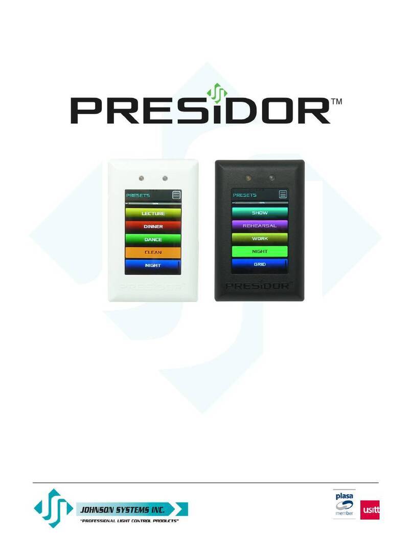
JOHNSON SYSTEMS Presidor Wall Station Assembly instructions

1923 Higheld Crescent S.E.
Calgary, Alberta, Canada T2G 5M1
tel: 403.287.8003
fax: 403.287.9003
e-mail: [email protected]
website: www.johnsonsystems.com
Wall Station (PWS)
Installation Guide and User Manual
JOHNSON SYSTEMS INC.
WWW.JOHNSONSYSTEMS.COM

WWW.JOHNSONSYSTEMS.COM
2
For Technical Assistance
1. Refer to your product user manual. The most current revision is
available online: www.johnsonsystems.com/presidor.htm
2. Contact the “point-of-sale” dealer or distributor from which this product
was originally purchased, and ask for technical assistance.
3. If neither of the above can provide you with the necessary information,
please contact our factory via email ([email protected])
or phone (403-287-8003) during business hours (Monday to Friday,
8:00AM to 5:00PM MST).
Contents
Characteristics .................................................................................................4
Drawings & Details ..........................................................................................4
Description of Operation ..................................................................................6
Installation .......................................................................................................6
Model PWS-70P-DMX .....................................................................................7
Model PWS-20P-RETRO ..............................................................................10
Installation Procedure ....................................................................................13
PWS Removal ..............................................................................................13
Replacement Plastic Kits ...............................................................................14
Presidor™ Adaptor Plates .............................................................................14
Presidor™ Surface Boxes .............................................................................14
Initial Set Up and Station Conguration.........................................................15
Power Up ..................................................................................................15
Main Menu ................................................................................................15
Initial Setup And Conguration .................................................................16
Recording A Preset ........................................................................................26
DMX Snapshot . ............................................................................................26
Program A Preset ..........................................................................................27
Preset Playback.............................................................................................29
Firmware Upgrades .......................................................................................29

WWW.JOHNSONSYSTEMS.COM 3
Introduction
DMX Snapshot and Multi-Zone Controls
Presidor™ Wall Stations (PWS) represent the next step in Architainment
Lighting Controls. Intuitive operation is coupled with state-of-the-art
capacitive touch technology permitting powerful distributed lighting controls
for single or multi-room environments. Attractive 1 gang “Patent Pending”
design is supported by color-matched adapter plates up to 7 gang and
surface mount back boxes. Supporting up to 70 presets on a single universe
of DMX512, a PWS can operate as either a DMX console or a DMX
snapshot/playback device. Flexible and programmable auxiliary contact
input, RS232 input and real-time scheduling allow for a myriad of interface
possibilities with Building Management and Show Control systems. Wiring
topology is fast, simple and inexpensive with standard Cat5/5e or Cat6
cabling using standard RJ-45 connectors or existing Belden #9773 wiring
using standard Phoenix style connectors. Daisy-chain up to 15 stations per
room for multi-room environments for up to 25 rooms when using one or
more Presidor™ Room Linker/Combiner (PRLC).
Typical applications are wide ranging from theatre house lights, moving
lights, LED xtures, churches, corporate boardrooms, hotel ballrooms,
convention facilities, museums, art galleries and other DMX512 or RS232
controlled devices.
Features
•
Attractive “Patent Pending” screwless design is ergonomic and sealed to dust.
• 70 presets on one universe of DMX512 channels.
• Operates as either a DMX console or a DMX snapshot/playback device.
• State-of-the-art high speed, low power “green” processor and ancillary
circuitry with a power consumption < 1⁄4 Watt.
• RS232 Input.
• Bluetooth ready for remote preset activation via cell phone.
• Dual integrated light pipes allow for both automatic proximity sense and
ambient light sense.
• Embedded programming with alphanumeric preset labeling.
• Intuitive navigation allows ease of operation.
• Unique interactive real-time functionality including manually activated digital
sliders.
• Password-protected access for customized security.
• Up to 15 daisy-chained stations per room/zone power and data inclusive
over Cat5/5e/6 or 3-Pair cable.
• Up to 25 rooms/zones per DMX universe with the use of Presidor™ Room
Linker/Combiner (PRLC).
• Small compact size permits installation in standard, readily available single
gang electrical back boxes.
• Available in white or black with optional color-matched adapter plates and
surface mount back boxes allow for virtually unlimited retrot possibilities.
• Patent Pending.
Presidor™ Wall Stations (PWS)
Presidor™ Room Linker/Combiner (PRLC)

WWW.JOHNSONSYSTEMS.COM
4
Characteristics
• Voltage: 5 - 48VDC operational range. 48VDC when used with PRLC-4 Room Linker/Combiner
(48VDC supplied by PRLC-4).
• Power Consumption: < 1 Watt per station during operation and < 1⁄4 Watt during standby mode.
• Cabling: Model #PWS-70P-DMX; RS485 Cat5/5e/6 cable (RJ-45) or retrot into existing Belden
#9773 or equivalent (terminal block), 300m max. (1000').
Model #PWS-20P-RETRO; 4 x #22 AWG or larger wires, Typical 1000' or 300m on
#18 AWG wiring.
• Operating Conditions: 0°C to 40°C (32°F to 105°F); 10-90% relative humidity, non-condensing.
Drawings & Details
Models: PWS-70P-DMX & PWS-20P-RETRO

WWW.JOHNSONSYSTEMS.COM
6
Settings Screen
1. DMX Channel Setup
2. Aux Switch Input
3. Schedule
4. Audio
5. Date/Time
6. Bluetooth (Future)
7. Motion Detection
8. Info
9. Sync And Lock
10. Password
11. Backlight
12. Preset Enable/Disable
Status LED's
Green – Room Linker Combiner
Blue – Bluetooth (Future)
Flashing Yellow – DMX wiring reversed
Status LED's
Description of Operation
Presidor™ Wall Stations (PWS) are designed to support up to 15 stations per room/zone wiring in a daisy-chain
topology. There must be a Main Station in each wiring LAN (Local Area Network) with one Main PWS per room/
zone. Each LAN and Main PWS may have up to 14 Secondary PWS’s connected to it. The Main PWS will output
DMX data for the room directly to the DMX receiving device or to a DMX input of a Presidor™ Room Linker
Combiner (PRLC-4) in a multi-room application.
Installation
There are two models of PWS, both are available in white or black.
Model# PWS-70P-DMX
Model# PWS-20P-RETRO
Although both models share the same operation, the installation and wiring of each is slightly different due to the
different data protocol used.

WWW.JOHNSONSYSTEMS.COM 7
Model PWS-70P-DMX
Model #PWS-70P-DMX is designed for new applications where CAT5/5e or CAT6 can be provided or retrot
applications where existing Belden #9773 exists. Capable of up to 70 presets, this model will accept DMX512
on its input and output DMX512 when congured as a room Main Station. Inter-room communication between
multiple PWS will be PMX multiplex (RS485) protocol.
Model PWS-70P-DMX Configuration and DIP Switch Settings
Important!
One station in each LAN must be designated as a Main PWS (switch 4 ON). Only one Main Station per
LAN. All Secondary PWS connected to the Main PWS (maximum 14 PWS) must have switch 4 turned OFF.
Important! Communication between Main PWS and Secondary PWS is PMX protocol (Presidor™ Multiplex).
This RS485 protocol requires active termination (switch 2 ON) on the rst and the last PWS in the LAN for each
room/zone.

WWW.JOHNSONSYSTEMS.COM
8
DIP SWITCH #2 ON FOR 1st & LAST
ROOM STATIONS
DIP SWITCH #2 ON FOR 1st & LAST
ROOM STATIONS
Typical PWS-70P-DMX Wiring and Connection Detail
Typical PWS-70P-DMX Single Room Wiring Topology #1
Typical PWS-70P-DMX Single Room Wiring Topology #2

WWW.JOHNSONSYSTEMS.COM 9
SECONDARY 2SECONDARY 1MAIN
DMX IN from
Console or DMX Source
AUX Sensor /
Contact
Cat 5/5e/6
Patch Cable
Cat 5/5e/6
Patch Cable
Cat 5/5e/6
Patch Cable
Cat 5/5e/6
Patch Cable
To Secondary
PWS 3-14
Typical PWS-70P-DMX Multi-room Wiring Topology
PWS-70P-DMX Cat 5/5e/6 Interconnect
PRLC - Room Linker Combiner

WWW.JOHNSONSYSTEMS.COM
10
Model PWS-20P-RETRO
Model PWS-20P-RETRO is designed specically for use in Heritage Buildings using existing wiring not capable
of RS485. Communication is performed via a proprietary Unipolar Bi-Directional (UBD) low baud rate protocol.
This permits digital control upgrades to facilities that would otherwise be faced with a very expensive wiring
replacement cost!
Minimum of 4 wires required. Maximum distance dependent on wire type and gauge.
Typical 1000' or 300m on #18 AWG wiring.
Model PWS-20P-RETRO Configuration and DIP Switch Settings
Important!
One station in each wiring LAN must be designated as a Main PWS (switch 4 ON). Only one Main Station
per LAN. All Secondary PWS connected to the Main PWS (maximum 14 PWS) must have switch 4 turned OFF.

WWW.JOHNSONSYSTEMS.COM
12
SECONDARY 2SECONDARY 1MAIN
DMX IN from
Console or DMX Source
AUX Sensor /
Contact
(Optional) Cat 5/5e/6
Patch Cable
To Secondary
PWS 3-14
PWS-20P-RETRO Multi Room Interconnect
PRLC - Room Linker Combiner
Typical PWS-20P-RETRO Multi-Room Wiring Topology

WWW.JOHNSONSYSTEMS.COM 13
Installation Procedure
Each PWS comes complete with a pre-assembled main sub-assembly, wall mounting plate and 6-32 mounting
hardware. PWS is designed for installation into standard grounded single gang electrical backboxes.
1. Ensure the electrical back box is grounded to earth ground via dedicated grounding wiring or through conduit
where electrical code permits. An un-grounded box may lead to damage from static electricity and void
warranty.
2. Clean back box of all debris including metal lings, dust, drywall or any other debris that could affect electrical
performance. Compressed air is best for this.
3. Check the back box 6-32” mount threads before attempting to install the wall mounting plate. This can be
easily done be spinning one of the supplied mounting screws clockwise with your ngers into each of the two
mounting holes. They should install easily with your ngers. If they do not, it is recommended to run a 6-32”
drill tap through the hole with a small reversable drill to “clean out” any bad threading.
4. Install the wall mounting plate ush to the wall and tighten with the supplied mounting screws snuggly as to not
deform the plastic but provide a tight t to the wall. Use a small level to ensure a plumb level installation of the
plate. DO NOT overtighten the mounting screws. Hand tightening is recommended over any power assist tool.
Important: DO NOT exceed 1.5 in. - lbf. for drywall and 5.0 in. - lbf. for Presidor™ Surface Boxes (PSB).
5. Label all wiring as “to or from” for future identication. Dress out all the wiring and terminate to the appropriate
connectors based on installation and PWS model type. Leave at least an 8-12” service loop if possible. Ensure
all wire is stripped back far enough to ensure full plug insertion without insulation. Plug all the terminated
wiring connectors to their nal location on the PWS I/O PCB. Tape off or heat-shrink any exposed shield wiring
or unused conductors that could touch the rear of the station and cause a short circuit.
6. Set the dip switches as required for Main/Secondary PWS, end-of-line termination. See chart on page 7 for
model# PWS-70P-DMX and page 10 for model# PWS-20P-RETRO.
7. Hook the PWS sub-assembly on to the top of the wall plate with the face panel light pipes facing upward.
Gently push to lower the PWS sub-assembly until contact is made with the wall plate. Apply rm pressure
against the bottom of the PWS sub-assembly until an audible “snap” is heard or felt. The PWS sub-assembly
should now be ush to the wall.
PWS Removal
Power OFF the PWS if possible.
To remove an installed PWS, a at head screwdriver with a slot width of 3/16” to ¼” will be required. Insert the
screwdriver into one of the two extraction holes on the bottom of the face panel sub-assembly. Gently and slowly
twist the screwdriver until the face panel “pops” away from the wall mount plate. It may be possible that procedure
is required for both extraction holes. Unhook the top of the subassembly from the top of the wall plate and gently
remove the station from the wall.
Hook PWS onto Wallplate at an angle.
Push down onto Wallplate.
Snap PWS onto Wallplate.
Wall
Electrical
Back Box

WWW.JOHNSONSYSTEMS.COM
14
Replacement Plastic Kits
PWS-MOUNT-W Replacement PWS Mounting Kit. 4 Piece Set, White.
PWS-MOUNT-B Replacement PWS Mounting Kit. 4 Piece Set, Black.
Presidor™ Adaptor Plates
For installation where oversize back boxes exist, Presidor™ Adaptor Plates are sized for exact t with Presidor™
Wall Stations (PWS). These rugged plates permit installation of PWS in a variety of gang wall boxes up to 7 gang.
Cut from 18-gauge steel and powder coated in white or black nish, these adaptor plates make installation of
PWS in existing back boxes a breeze!
Model Description
PA-2A1-White 2 gang to 1 gang Adaptor Plate, White
PA-2A1-Black 2 gang to 1 gang Adaptor Plate, Black
PA-2A1-DMX-White 2 gang to 1 gang Adaptor Plate, White c/w 5 pin XLR DMX Input
PA-2A1-DMX-Black 2 gang to 1 gang Adaptor Plate, Black c/w 5 pin XLR DMX Input
PA-3A1-White 3 gang to 1 gang Adaptor Plate, White
PA-3A1-Black 3 gang to 1 gang Adaptor Plate, Black
PA-4A1-White 4 gang to 1 gang Adaptor Plate, White
PA-4A1-Black 4 gang to 1 gang Adaptor Plate, Black
PA-5A1-White 5 gang to 1 gang Adapter Plate, White
PA-5A1-Black 5 gang to 1 gang Adapter Plate, Black
PA-6A1-White 6 gang to 1 gang Adapter Plate, White
PA-6A1-Black 6 gang to 1 gang Adapter Plate, Black
PA-7A1-White 7 gang to 1 gang Adapter Plate, White
PA-7A1-Black 7 gang to 1 gang Adapter Plate, Black
Presidor™ Surface Boxes
For installations where surface mount backboxes are required we offer high quality options. Designed specically
for Presidor™ Wall Stations (PWS), these rugged 18-gauge steel boxes feature welded seams, pre-tapped
6-32 holes for precise station mounting and 5 laser cut conduit entry options. These boxes allow for precision
alignment of an installed PWS with no over-hang or sharp edges. Available in white or black powder coat nish in
single or two gang sizes.
PSB-1-White 1 gang Surface Box, White.
PSB-1-Black 1 gang Surface Box, Black.
PSB-2-White 2 gang Surface Box, White.
PSB-2-Black 2 gang Surface Box, Black.
For more information please go to https://www.johnsonsystems.com/presidor_surface_boxes.htm

WWW.JOHNSONSYSTEMS.COM 15
Main Screen
1. Low Power Sleep Mode
2. Presets
3. Clean Screen
4. Settings
5. Reset Device
Info Screen
1. Room Number
2. Model Number
3. Firmware Version
4. Serial Number
5. System Voltage
6. Factory Default. Only
for Admin Users
Initial Set Up and Station Configuration
• POWER UP
• Upon power up, the PWS will briey display the Presidor™ logo
and will then default to the preset page that was last active before
power down. In the case of a new station it is shipped from the
factory defaulted with the rst 10 presets only and displayed on
two pages of ve presets each in the color of teal.
• MAIN MENU
• Pressing the MENU function icon in the upper right of the display
screen will pull up the following screen:
1. LOW POWER SLEEP MODE - Activates PWS ultra low
power mode for energy saving and displays graphic logo
image from memory. Two minutes of inactivity on the station
will automatically initiate the SLEEP MODE. Two levels of
illumination are programmable for this setting. The station
will automatically exit this mode and wake up to PRESET
MODE if the display is touched or if any motion is detected
by the proximity sensor within the range it is programmed for
(maximum 3 meters or 10 feet).
2. PRESETS - Normal Run mode for any PWS. Allows access
to all selected PRESETS for that PWS. Push any PRESET
for playback. Last action will always override the previous
action.
3. CLEAN SCREEN - Permits the temporary disabling of the
capacitive touch interface/keypad to allow for cleaning of the
glass without affecting room lighting. A white screen with 30
second countdown timer will display when activated. Note
there is no exit from this menu, you must wait for the 30
second timeout.
4. SETTINGS - Direct access to all the PWS Set up and
Conguration SETTINGS.
5. RESET PWS. Permits a soft reboot of the PWS without
affecting stored data or room lighting levels. RESET will only
show for ADMIN Users.

WWW.JOHNSONSYSTEMS.COM
16
Settings Screen
1. DMX Channel Setup
2. Aux Switch Input
3. Schedule
4. Audio
5. Date/Time
6. Bluetooth (Future)
7. Motion Detection
8. Info
9. Sync And Lock
10. Password
11. Backlight
12. Preset Enable/Disable
Status LED's
Green – Room Linker Combiner
Blue – Bluetooth (Future)
Yellow – DMX In
Status LED's
• INITIAL SETUP AND CONFIGURATION
• Pressing the SETTINGS icon (4 above) right of the screen will
access the SETTINGS menu where conguration and customization
of each PWS can be performed.
Each icon will access a screen menu page permitting customization of each
PWS. It is recommended that the PWS be programmed in the following
order:
Essential Conguration
1. PASSWORD - Security enable various PWS functions through two
levels of password permission access. See PASSWORD in the
manual for factory default codes and instructions to change.
2. DMX CHANNEL SETUP - Permits the selection (unmasking) of
specic DMX channels that the PWS will output. PWS are shipped
from the factory fully masked with no channels selected. Each
channel can be assigned as a dimmer (DIM), non-dim (ND) or task
light (TASK).
3. PRESET ENABLE/DISABLE - PWS are shipped defaulted with the
rst 10 presets enabled. Up to 70 presets are available in 7 different
colors. Enable the desired number of presets.
4. DATE/TIME - Set the date and time in various display formats.
5. SYNC AND LOCK - Synchronize any Secondary PWS connected
to the room Main PWS. Relevant data will be shared from the Main
to the Secondary PWS (maximum 14 Secondary PWS per room).
Optional Conguration
6. AUX SWITCH INPUT - Select the type of contact input and the
preset choice(s) upon input activation and/or disable.
7. SCHEDULE - Selection of up to 70 presets for automatic activation
via the onboard Real Time Clock (RTC). One minute increments
24/7/365.
8. AUDIO - Selection of audio type and volume.
9. MOTION DETECTION - Sensitivity selection of the proximity sensor
for auto recognition.
10. BACKLIGHT - Sensitivity selection of the ambient light sensor for
desired level of station illumination.
11. BLUETOOTH (FUTURE) - Available 1Q 2021.
12. INFO - Critical system information as displayed on next page (top
right).

WWW.JOHNSONSYSTEMS.COM 17
Info Screen
1. Room Number
2. Model Number
3. Firmware Version
4. Serial Number
5. System Voltage
Important! Do not access FACTORY
DEFAULT unless intentional.
An ADMIN could accidently overwrite
all programmed data.
1. PASSWORD / SECURITY LOCK
Each PWS requires a valid Password entry to access certain functions.
Access via the Security Lock icon, the lock will display red when locked and
green when unlocked. Each PWS will default to a “locked” state with access
to only select functions for protection of programing and restriction of use. A
small red lock will appear in the upper left of the display when in the locked
state. Only preset playback and minor edits of preset levels are permitted in the
secure “locked” state.
Each PWS has two passwords to permit controlled access to specic menu
functions:
USER: Factory default “12345” - allows limited access to screens.
ADMIN: Factory default “98765” - allows full access to all screens.
Passwords must always be a 5 digit number. The password is stored in
the removable external EEPROM plug in module on the rear of the PWS.
Passwords are entered at the room Main PWS only and then shared with the
room Secondary PWS via the SYNC command.
Important! On SYNC Main/Secondary, all Secondary PWS will have the same
password as the room/zone Main PWS. The user will not be able to change
the password on a Secondary either manually or with the DIPSW. This function
and option is reversed to the Main Station for the room only.
Password privileges for the PWS are shown below:
The PASSWORD entry screen is shown at right:
Enter the PASSWORD and press [OK]. If the PASSWORD is correct, the
PASSWORD screen will close and take you back to the main screen.
The screens will lock again if:
a) PWS goes to sleep (no keys for 5 minutes).
b) Enter the PASSWORD screen and press [c] and exit without pressing OK.
c)
For the PRESET Edit screen, upon exiting the PRESET Edit mode (USER only).
If the PASSWORD is incorrect, the screen will show (at right):
Screen Password Level
MainScreen ADMIN
PSEnableScreen ADMIN
InfoScreen ADMIN
DateTimeScreen USER
DMXSetupScreen ADMIN
ScheduleScreen ADMIN
AUXScreen ADMIN
SyncScreen ADMIN
BLEScreen ADMIN
PresetEditScreen *ADMIN / USER

WWW.JOHNSONSYSTEMS.COM
18
NEW USER PASSWORD
A new USER PASSWORD may be entered in two ways:
a) Enter the old PASSWORD, press [OK]. If you return to the PASSWORD
screen before a sleep timeout, the [n] key will now be active. Pressing
the [n] key will show “NewUP”. A New USER PASSWORD entry will
always be displayed in red to distinguish it from the normal password
entry mode. Enter a new 5 digit User PASSWORD and press OK.
Remember your New USER PASSWORD or document it somewhere
for future reference.
b) If the user forgets their password, setting DIPSW 3 ON will allow the
user to enter a new password. This procedure will involve the temporary
removal of the Main PWS from the wall, please see page 13. This must
be done carefully with the power remaining ON.
PWS Rear Panel View
When DIPSW 3 is on, 4 Red bars are shown on the password screen and the
[n] key is now active.
Enter a new 5 digit User PASSWORD and press OK. Remember your New
User Password or document it somewhere for future reference. Switch
DIPSW 3 back to the OFF position and re-install the PWS Main Station back
into the wall. A USER may only reset the USER PASSWORD.

WWW.JOHNSONSYSTEMS.COM 19
NEW ADMIN PASSWORD
A System Administrator can reset both the ADMIN and USER PASSWORD's and
access all programming features of the PWS.
Pressing the [n] key will toggle between the following two screens, or an ADMIN
USER can reset both.
This allows either the ADMIN or USER password to be reset depending on which is
selected. Screens that require a PASSWORD to access will show a small red lock
symbol at the top left side of the screen (see right).
Once unlocked with a valid PASSWORD entry, the screen will allow access to
additional functions on the screen (see the tool/wrench that now appears below).
This allows additional set menus for an ADMIN level person and is covered in more
detail further in this manual.
Important! Security timeout. After 2 minutes of inactivity, the PWS ADMIN level
access will automatically time out to prevent unauthorized access to the Master
PWS conguration set up and data.

WWW.JOHNSONSYSTEMS.COM
20
2. DMX SETUP
Main PWS DMX set up. ADMIN security access only. This menu is used to set up the DMX mask for each room,
congure the operation of room specic (unmasked) channels, and set the external DMX source input priority in
conjunction with the PWS Main station DMX output.
Pressing the DMX icon in the SETTINGS menu will allow access to the DMX SETUP page.
DIM = Yellow = Dimmer assignment to that specic DMX output channel permitting a full range of DMX control
output from 0-100% from the Main PWS.
ND = Green = Non-Dim assignment to that specic channel permitting toggle between 0% and 100% DMX control
output with a trigger point of approximately 3% DMX.
TASK = Blue = Non-Dim of specic channels for operation within any preset or independent operation outside
of the active preset between multiple Secondary (entrance) PWS stations (room within a room operation). TASK
assignment to a specic DMX channel or group of channels permits toggle (Non-Dim control) between 0% and
100% DMX control output with a trigger point of approximately 3% DMX. “Room with a room” operation is limited
to presets 61-70. Task lights assigned in presets 1- 60 will operate as Non-Dims only on preset execution.
Example: TASK circuit assignment. Several grid blue (safety) light circuits that require control from multiple
entrance (Secondary PWS) locations. The need for all entrance (Secondary PWS) stations to mimic the active
TASK light preset and operate as a “room within a room” without affecting the underlying active preset 1-60 that
the room Main PWS is outputting in DMX.
Below is an example of a 28 DMX channel room conguration where:
• channels 1-11, 13-15, 17,18, 21-24 are set as Dimmers (DIM).
• channels 12, 16, 19 & 20 are set as Non-Dims (ND).
• channels 25- 28 are set as Non-Dim TASK lights (TASK).
Menu down arrow above will access DMX output channels in groups of
32 channels per page up to 512 channels.
This manual suits for next models
1
Table of contents
Other JOHNSON SYSTEMS Control Unit manuals
Popular Control Unit manuals by other brands

Murphy
Murphy Selectronic TTD Series Installation and operation manual

Benewake
Benewake TFmini-i LIDAR product manual

Emerson
Emerson SEMPELL Installation and maintenance instructions

Santec
Santec ECL-200 quick start guide

Festo
Festo CPV-D102 Elektronics manual

Siemens
Siemens SIM-16RC installation instructions

Microchip Technology
Microchip Technology RN4870 manual

VigilLink
VigilLink VLIP-SD10G-ECRD user manual

Quick
Quick TCD 2022 Installation and use manual

Mitsubishi
Mitsubishi MELSEC-A A1S68AD user manual

Siemens
Siemens SITRANS F M MAG 8000 operating instructions

Johnson Controls
Johnson Controls UL Listed GS-20 Series manual