Jonsered GT 2124 User manual

Bedienungsanweisung
Manual de instrucciones
Libretto d’Istruzioni
Lesen Sie diese Hinweise zur Handhabung des
Geräts aufmerksam durch. Verwenden Sie es erst,
wenn Sie sicher sind, daß Sie alle Anweisungen
verstanden haben.
Lea atentamente las instrucciones y asegúrese de
entenderlas antes de utilizar este unidad.
Leggere attentamente queste istruzioni e accertarsi
di averle comprese prima di usare l’unità.
545076664 1/3/06
Deutsch
Italiano
Español
Instruction Manual
Manuel d’instructions
English
Français
Please read these instructions carefully and make
sure you understand them before using this unit.
Avant d’utiliser cet appareil, veuillez lire attentive-
ment les instructions et assurez--vous de les avoir
comprises.
ENGLISH FRANÇAIS DEUTSCH ITALIANO
ESPANOL
Lees deze instructies zorgvuldig en wees er zeker
van dat u ze begrijpt alvorens dit apparaat te gebrui-
ken.
Handleiding
Nederlands
NEDERLANDS
JONSERED SERVICE

2
IDENTIFICATION (WHAT IS WHAT?)
Shield
Choke
Primer Bulb
ON/OFF
Switch
Trimmer head
Tube
Assist handle
Throttle
Fuel tank
Assist handle adjustment
Starter
Handle
Manual
Muffler
Wrench
IDENTIFICATION OF SYMBOLS
A. WARNING! This trimmer can be dangerous! Careless or improper use can cause
serious or even fatal injury.
B. Read and understand the instruction manual before using the trimmer.
C. With this handle, only use trimmer head. Never use blades or flailing devices with this
tool.
D. WARNING! The trimmer line can throw objects violently. You can be blinded or
injured. Always wear eye protection.
E. Always use:
Ear protection
Protective glasses or visor
F. Assist handle to be positioned only below the arrow.
G. The operator of the machine must insure that no one comes within a 15 meter radius
while working. When several operators are working within the same area a safety dis-
tance of at least 15 meters must be observed.
H. Use unleaded or quality leaded petrol and two--stroke oil mixed at a ratio of 2.5%.
I. Engine ON/OFF Switch.
J. Guaranteed sound power level according to Directive 2000/14/EC
K. Maximum rotational frequency of the spindle, rpm
L. Sound pressure level at 7,5 meters

3
SAFETY RULES
WARNING: When using gardening
appliances, basic safety precautions should al-
ways be followed to reduce the risk of fire and
serious injury. Read and follow all instructions.
This power unit can be dangerous! Operator is
responsible for following instructions and warn-
ings on unit and in manual. Read entire instruc-
tion manual before using unit! Be thoroughly fa-
miliar with the controls and the proper use of the
unit. Restrict the use of this unit to persons who
read, understand, and follow instructions and
warnings on unit and in manual. Never allow
children to operate this unit.
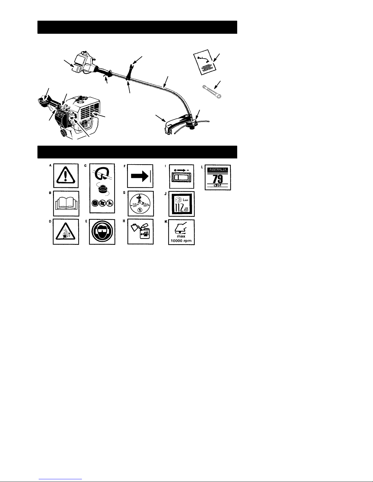
SAFETY INFORMATION
ON THE UNIT
INSTRUCTION
MANUAL
DANGER: Never use blades, wire, or
flailing devices. This unit is designed for line
trimmer use only. Use of any other accessories
or attachments will increase the risk of injury.
WARNING: Trimmer line throws ob-
jects violently. You and others can be blinded/
injured. Wear safety glasses and leg protec-
tion. Keep body parts clear of rotating line.
Safety Glasses or similar eye protection
Boots
Hazard Zone
15 meters
Keep children, bystanders, and animals 15 me-
ters away. If approached stop unit immediately.
If situations occur which are not covered in
this manual, use care and good judgement. If
you need assistance, contact your authorized
service dealer.
OPERATOR SAFETY
SDress properly. Always wear safety
glasses or similar eye protection when op-
erating, or performing maintenance, on
your unit (safety glasses are available).
Eye protection should be marked Z87.
SAlways wear face or dust mask if operation
is dusty.
SAlways wear heavy, long pants, long
sleeves, boots, and gloves. Wearing safety
leg guards is recommended.
SAlways wear foot protection. Do not go
barefoot or wear sandals. Stay clear of
spinning line.
SSecure hair above shoulder length. Secure
or remove loose clothing or clothing with
loosely hanging ties, straps, tassels, etc.
They can be caught in moving parts.
SBeing fully covered also helps protect you
from debris and pieces of toxic plants
thrown by spinning line.
SStay Alert. Do not operate this unit when you
are tired, ill, upset or under the influence of al-
cohol, drugs, or medication. Watch what you
are doing; use common sense.
SWear hearing protection.
SNever start or run inside a closed room or
building. Breathing exhaust fumes can kill.
SKeep handles free of oil and fuel.
UNIT / MAINTENANCE SAFETY
SDisconnect the spark plug before performing
maintenance except carburetor adjustments.
SLook for and replace damaged or loose
parts before each use. Look for and repair
fuel leaks before use. Keep in good working
condition.
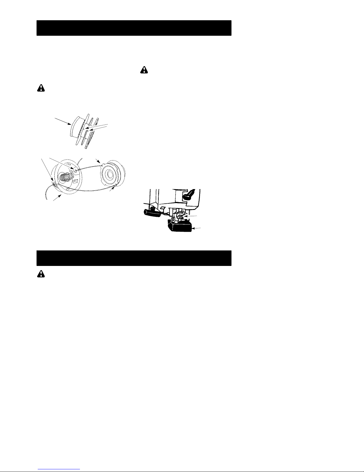
SReplace trimmer head parts that are
chipped, cracked, broken, or damaged in
any other way before using the unit.
SMaintain unit according to recommended
procedures. Keep cutting line at proper
length.
SUse only 2 mm diameter Jonsered®brand
line. Never use wire, rope, string, etc.
SInstall required shield properly before using
the unit. Use only specified trimmer head;
make sure it is properly installed and se-
curely fastened.
SMake sure unit is assembled correctly as
shown in this manual.
SMake carburetor adjustments with lower
end supported to prevent line from contact-
ing any object.
SKeep others away when making carburetor
adjustments.
SUse only recommended Jonsered®acces-
sories and replacement parts.
SHave all maintenance and service not ex-
plained in this manual performed by an au-
thorized service dealer.
FUEL SAFETY
SMix and pour fuel outdoors.
SKeep away from sparks or flames.
SUse a container approved for fuel.
SDo not smoke or allow smoking near fuel or
the unit.
SAvoid spilling fuel or oil. Wipe up all fuel spills.
SMove at least 3 meters away from fueling
site before starting engine.
SStop engine and allow to cool before re-
moving fuel cap.
SAlways store gasoline in a container ap-
proved for flammable liquids.

4
CUTTING SAFETY
WARNING: Inspect the area before
each use. Remove objects (rocks, broken
glass, nails, wire, etc.) which can be thrown
by or become entangled in line. Hard objects
can damage the trimmer head and be thrown
causing serious injury.
SUse only for trimming, scalping, mowing
and sweeping. Do not use for edging, prun-
ing or hedge trimming.
SKeep firm footing and balance. Do not over-
reach.
SKeep all parts of your body away from muf-
fler and spinning line. Keep engine below
waist level. A hot muffler can cause serious
burns.
SCut from your right to your left. Cutting on
left side of the shield will throw debris away
from the operator.
SUse only in daylight or good artificial light.
SUse only for jobs explained in this manual.
TRANSPORTING AND STORAGE
SAllow the engine to cool; secure unit before
storing or transporting in vehicle.
SEmpty fuel tank before storing or transport-
ing the unit. Use up fuel left in the carburetor
by starting engine and letting it run until it
stops.
SStore unit and fuel in an area where fuel va-
pors cannot reach sparks or open flames
from water heaters, electric motors or
switches, furnaces, etc.
SStore unit so line limiter cannot accidentally
cause injury. Unit can be hung by the tube.
SStore the unit out of the reach of children
SPECIAL NOTICE: Exposure to vibra-
tions through prolonged use of gasoline pow-
ered hand tools could cause blood vessel or
nerve damage in the fingers, hands, and
joints of people prone to circulation disorders
or abnormal swellings. Prolonged use in cold
weather has been linked to blood vessel dam-
age in otherwise healthy people. If symptoms
occur such as numbness, pain, loss of
strength, change in skin color or texture, or
loss of feeling in the fingers, hands, or joints,
discontinue the use of this tool and seek med-
ical attention. An anti-vibration system does
not guarantee the avoidance of these prob-
lems. Users who operate power tools on a
continual and regular basis must monitor
closely their physical condition and the condi-
tion of this tool.
ASSEMBLY
WARNING: Make sure unit is proper-
ly assembled and all fasteners are secure.
Examine parts for damage. Do not use dam-
aged parts.
It is normal for the fuel filter to rattle in the
empty fuel tank.
Finding fuel or oil residue on muffler is normal
due to carburetor adjustments and testing
done by the manufacturer.
ADJUSTING THE HANDLE
WARNING: When adjusting the han-
dle, be sure it remains between the trigger
and the safety label. Assist handle must be
positioned only below the arrow.
1. Loosen wing nut on handle.
2. Rotate the handle on the tube to an up-
right position; retighten wing nut.
ATTACHING THE SHIELD
WARNING: The shield must be prop-
erly installed. The shield provides partial
protection from the risk of thrown objects to
the operator and others and is equipped with
a line limiter which cuts excess line. The line
limiter (on underside of shield) is sharp and
can cut you.
1. Remove nut from shield.
2. Insert bracket into slot on shield.
3. Pivot shield until bolt passes through hole
in bracket.
4. Reinstall nut and tighten securely with
wrench (provided).
Slot
Shield
Nut
Bracket
Line Limiter Blade

5
OPERATION
WARNING: Be sure to read the fuel
information in the safety rules before you be-
gin. If you do not understand the safety rules,
do not attempt to fuel your unit. Contact an
authorized service dealer.
FUELING ENGINE
WARNING: Remove fuel cap slowly
when refueling.
This engine is certified to operate on un-
leaded gasoline. Before operation, gasoline
must be mixed with a good quality 2-cycle air-
cooled engine oil mixed at a ratio of 40:1
(2.5%). A 40:1 ratio is obtained by mixing 5
liters of unleaded gasoline with 0,125 liter of
oil. DO NOT USE automotive oil or boat oil.
These oils will cause engine damage. When
mixing fuel, follow instructions printed on oil
container. Once oil is added to gasoline,
shake container momentarily to assure that
the fuel is thoroughly mixed. Always read and
follow the safety rules relating to fuel before
fueling your unit.
IMPORTANT
Experience indicates that alcohol blended
fuels (called gasohol or using ethanol or
methanol) can attract moisture which leads to
separation and formation of acids during stor-
age. Acidic gas can damage the fuel system
of an engine while in storage. To avoid engine
problems, empty the fuel system before stor-
age for 30 days or longer. Drain the gas tank,
start the engine and let it run until the fuel lines
and carburetor are empty. Use fresh fuel next
season. Never use engine or carburetor
cleaner products in the fuel tank or permanent
damage may occur.
HOW TO STOP YOUR UNIT
STo stop the engine, move the ON/OFF
switch to the OFF position.
HOW TO START YOUR UNIT
WARNING: The trimmer head will
turn while starting the engine. Avoid any con-
tact with the muffler. A hot muffler can cause
serious burns.
STARTING A COLD ENGINE (or a
warm engine after running out of fuel)
Starting Position
Choke
Lever
Primer Bulb
Starter Handle
Muffler
1. Set unit on a flat surface.
2. Move ON/OFF switch to the ON position.
3. Slowly press the primer bulb 6 times.
4. Move choke lever to FULL CHOKE posi-
tion.
5. Squeeze and hold trigger through all re-
maining steps.
6. Pull starter rope handle sharply until en-
gine sounds as if it is trying to start, but do
not pull rope more than 6 times.
7. As soon as engine sounds as if it is trying
to start, move choke lever to HALF
CHOKE.
8. Pull starter rope sharply until engine runs,
but no more than 6 pulls. If the engine
doesn’t start after 6 pulls (at the HALF
CHOKE position), move the choke lever
to the FULL CHOKE position and press
the primer bulb 6 times. Squeeze and hold
the throttle trigger and pull the starter rope
2 more times. Move the choke lever to the
HALF CHOKE position and pull the start-
er rope until the engine runs, but no more
than 6 pulls. NOTE: If engine still
doesn’t start, it is probably flooded. Pro-
ceed to STARTING A FLOODED EN-
GINE.
9. Once the engine starts, allow it to run 10
seconds, then move the choke lever to
OFF CHOKE. Allow the unit to run for 30
more seconds at OFF CHOKE before re-
leasing the throttle trigger. NOTE: If en-
gine dies with the choke lever in the OFF
CHOKE position, move the choke lever to
the HALF CHOKE position and pull the
rope until engine runs, but no more than 6
pulls.
STARTING A WARM ENGINE
1. Move ON/OFF switch to the ON position.
2. Move the choke lever to the HALF
CHOKE position.
3. Squeeze and hold the throttle trigger.
Keep throttle trigger fully squeezed until
the engine runs smoothly.
4. Pull starter rope sharply until engine runs,
but no more than 5 pulls.
5. Allow engine to run 15 seconds, then
move the choke lever to the OFF CHOKE
position.

6
NOTE: If engine has not started, pull starter
rope 5 more pulls. If engine still does not run, it
is probably flooded.
STARTING A FLOODED ENGINE
Flooded engines can be started by placing
the choke lever in the OFF CHOKE position;
then, pull the rope to clear the engine of ex-
cess fuel. This could require pulling the starter
handle many times depending on how badly
the unit is flooded.
If the unit still doesn’t start, refer to TROU-
BLESHOOTING TABLE.
OPERATING INSTRUCTIONS
OPERATING POSITION
Eye Protection
Long Pants
Heavy Shoes
A
L
W
A
Y
SWE
A
R:
Cut from your right to your left.
Hearing
Protection
WARNING: Always wear eye protec-
tion and hearing protection. Never lean over
the trimmer head. Rocks or debris can rico-
chet or be thrown into eyes and face and
cause blindness or other serious injury.
Do not run the engine at a higher speed than
necessary. The cutting line will cut efficiently
when the engine is run at less than full throttle.
At lower speeds, there is less engine noise and
vibration. The cutting line will last longer and will
be less likely to “weld” onto the spool.
Always release the throttle trigger and allow the
engine to return to idle speed when not cutting.
To stop engine:
SRelease the throttle trigger.
SMove the ON/OFF switch to the OFF posi-
tion.
TRIMMER LINE ADVANCE
Advance line by tapping the bottom of the cut-
ting head lightly on the ground while engine is
running at full speed. The metal line limiter
blade attached to the guard will cut the line to
the proper length.
WARNING: Use only 2 mm diameter
round line. Other sizes and shapes of line will
not advance properly and will result in improp-
er cutting head function or can cause serious
injury. Do not use other materials such as
wire, string, rope, etc. Wire can break off dur-
ing cutting and become a dangerous missile
that can cause serious injury.
CUTTING METHODS
WARNING: Use minimum speed and
do not crowd the line when cutting around
hard objects (rock, gravel, fence posts, etc.),
which can damage the trimmer head, become
entangled in the line, or be thrown causing a
serious hazard.
SThe tip of the line does the cutting. You will
achieve the best performance and mini-
mum line wear by not crowding the line into
the cutting area. The right and wrong ways
are shown below.
Tip of the Line
Does The Cutting
Right Wrong
Line Crowded Into
Work Area
SThe line will easily remove grass and
weeds from around walls, fences, trees and
flower beds, but it also can cut the tender
bark of trees or shrubs and scar fences.
SFor trimming or scalping, use less than full
throttle to increase line life and decrease
head wear, especially:
SDuring light duty cutting.
SNear objects around which the line can-
wrap such as small posts, trees or fence
wire.
SFor mowing or sweeping, use full throttle for
a good clean job.
TRIMMING -- Hold the bottom of the trimmer
head about 80 mm above the ground and at
an angle. Allow only the tip of the line to make
contact. Do not force trimmer line into work
area.
Trimming
3 in. (8 cm)
Above Ground
SCALPING -- The scalping technique re-
moves unwanted vegetation. Hold the bottom
of the trimmer head about 80 mm above the
ground and at an angle. Allow the tip of the line
to strike the ground around trees, posts,
monuments, etc. This technique increases
line wear.
Scalping

7
MOWING -- Your trimmer is ideal for mowing
in places conventional lawn mowers cannot
reach. In the mowing position, keep the line
parallel to the ground. Avoid pressing the
head into the ground as this can scalp the
ground and damage the tool.
Mowing
SWEEPING -- The fanning action of the rotat-
ing line can be used for a quick and easy
clean up. Keep the line parallel to and above
the surfaces being swept and move the tool
from side to side.
Sweeping
MAINTENANCE
WARNING: Disconnect the spark
plug before performing maintenance except
for carburetor adjustments.
CHECK FOR LOOSE
FASTENERS AND PARTS
SSpark Plug Boot
SAir Filter
SHousing Screws
SAssist Handle Screw
SDebris Shield
CHECK FOR DAMAGED OR
WORN PARTS
Contact an authorized service dealer for re-
placement of damaged or worn parts.
SON/OFF Switch -- Ensure ON/OFF func-
tions properly by moving the switch to the
OFF position. Make sure engine stops;
then restart engine and continue.
SFuel Tank -- Discontinue use of unit if fuel
tank shows signs of damage or leaks.
SDebris Shield -- Discontinue use of unit if
debris shield is damaged.
INSPECT AND CLEAN UNIT AND
LABELS
SAfter each use, inspect complete unit for
loose or damaged parts. Clean the unit and
labels using a damp cloth with a mild deter-
gent.
SWipe off unit with a clean dry cloth.
CLEAN AIR FILTER
A dirty air filter decreases engine perform-
ance and increases fuel consumption and
harmful emissions. Always clean after every
5 hours of operation.
1. Clean the cover and the area around it to
keep dirt from falling into the carburetor
chamber when the cover is removed.
2. Remove parts as illustrated.
NOTE: Do not clean filter in gasoline or other
flammable solvent to avoid creating a fire haz-
ard or producing harmful evaporative emis-
sions.
3. Wash the filter in soap and water.
4. Allow filter to dry.
5. Add a few drops of oil to the filter; squeeze
the filter to distribute oil.
6. Replace parts.
Air Filter
Cover
Air Filter
Screws
REPLACE SPARK PLUG
Replace the spark plug each year to ensure
the engine starts easier and runs better. Set
spark plug gap at 0,6 mm. Ignition timing is
fixed and nonadjustable.
1. Twist, then pull off spark plug boot.
2. Remove spark plug from cylinder and dis-
card.
3. Replace with Champion RCJ-6Y spark
plug and tighten securely with a 19 mm
socket wrench.
4. Reinstall the spark plug boot.

8
SERVICE AND ADJUSTMENTS
REPLACING THE LINE
1. Move the ON/OFF switch to the OFF
position.
2. Disconnect the spark plug lead wire.
3. Remove spool by firmly pulling on tap but-
ton. Clean entire surface of hub and
spool. Replace with a pre-wound spool, or
cut two lengths of 4 meters of 2 mm diam-
eter line.
WARNING: Never use wire, rope,
string, etc., which can break off and become a
dangerous missile.
4. Insert ends of the line about 1 cm into the
small hole on the inside of spool.
Small
Holes
Spool
Hub
Line in Notch
Line in Notch
Line exit holes
5. Wind the line evenly and tightly onto the
spool. Wind in the direction of the arrows
found on the spool.
6. Push the line into the notches, leaving 7 --
12 cm unwound.
7. Insert the line into the the exit holes in the
hub as shown in the illustration.
8. Align the notches with the line exit holes.
9. Push spool into hub until it snaps into
place.
10. Pull the lines extending outside of the hub
to release them from the notches.
CARBURETOR ADJUSTMENT
WARNING: Keep others away when
making idle speed adjustments. The trimmer
head will be spinning during this procedure.
Wear your protective equipment and observe
all safety precautions.
The carburetor has been carefully set at the
factory. Adjustments may be necessary if you
notice any of the following conditions:
SEngine will not idle when the throttle is re-
leased.
Make adjustments with the unit supported so
the cutting attachment is off the ground and
will not make contact with any object. Hold
the unit by hand while running and making ad-
justments. Keep all parts of your body away
from the cutting attachment and muffler.
Idle Speed Adjustment
Allow engine to idle. Adjust speed until engine
runs without stalling (idle speed too slow).
STurn idle speed screw clockwise to in-
crease engine speed if engine stalls or dies.
STurn idle speed screw counterclockwise to
decrease engine speed.
Air Filter
Cover
Idle Speed
Screw
If you require further assistance or are unsure
about performing this procedure, contact an
authorized service dealer.
STORAGE
WARNING: Perform the following
steps after each use:
SAllow engine to cool before storing or trans-
porting.
SStore unit and fuel in a well ventilated area
where fuel vapors cannot reach sparks or
open flames from water heaters, electric
motors or switches, furnaces, etc.
SEmpty fuel tank before storing or transport-
ing the unit.
SStore unit and fuel well out of the reach of
children.
SStore unit with all guards in place. Position
unit so that any sharp object cannot acci-
dentally cause injury.
SEASONAL STORAGE
Prepare unit for storage at end of season or if
it will not be used for 30 days or more.
If your unit is to be stored for a period of time:
SClean the entire unit before lengthy stor-
age.
SStore in a clean dry area.
SLightly oil external metal surfaces.
ENGINE
SRemove spark plug and pour 1 teaspoon of
40:1, 2-cycle engine oil (air cooled) through
the spark plug opening. Slowly pull the
starter rope 8 to 10 times to distribute oil.
SReplace spark plug with new one of recom-
mended type and heat range.

9
SClean air filter.
SCheck entire unit for loose screws, nuts,
and bolts. Replace any damaged, broken,
or worn parts.
SAt the beginning of the next season, use
only fresh fuel having the proper gasoline to
oil ratio.
OTHER
SDo not store gasoline from one season to
another.
SReplace your gasoline can if it starts to rust.
TROUBLE CAUSE REMEDY
Engine will not
start. 1. ON/OFF switch in OFF
position.
2. Engine flooded.
3. Fuel tank empty.
4. Spark plug not firing.
5. Fuel not reaching
carburetor.
6. Carburetor requires
adjustment.
1. Move ON/OFF switch to ON position.
2. See “Starting a Flooded Engine” in
Operation Section.
3. Fill tank with correct fuel mixture.
4. Install new spark plug.
5. Check for dirty fuel filter; replace.
Check for kinked or split fuel line;
repair or replace.
6. Contact an authorized service dealer.
Engine will
not idle
properly.
1. Carburetor requires
adjustment.
2. Crankshaft seals worn.
3. Compression low.
1. See “Carburetor Adjustment” in
Service and Adjustments Section.
2. Contact an authorized service dealer.
3. Contact an authorized service dealer.
1. Air filter dirty.
2. Spark plug fouled.
3. Carburetor requires
adjustment.
4. Carbon build-up on
muffler outlet screen.
5. Compression low.
Engine will not
accelerate,
lacks power,
or dies under
a load.
1. Clean or replace air filter.
2. Clean or replace plug
and regap.
3. Contact an authorized service dealer.
4. Contact an authorized service dealer.
5. Contact an authorized service dealer.
Engine
smokes
excessively.
1. Choke partially on.
2. Fuel mixture incorrect.
3. Air filter dirty.
4. Carburetor requires
adjustment.
1. Adjust choke.
2. Empty fuel tank and refill with
correct fuel mixture.
3. Clean or replace air filter.
4. Contact an authorized service dealer.
Engine runs
hot.
1. Fuel mixture incorrect.
2. Spark plug incorrect.
3. Carburetor requires
adjustment.
4. Carbon build-up on
muffler outlet screen.
1. Empty fuel tank and refill with
correct fuel mixture.
2. Replace with correct spark plug.
3. Contact an authorized service dealer.
4. Contact an authorized service dealer.
WARNING: Always stop unit and disconnect spark plug before performing all of the
recommended remedies below except remedies that require operation of the unit.
TROUBLESHOOTING TABLE

10
DECLARATION OF CONFORMITY
relating to 2000/14/EC
EC Declaration of Conformity relating to 2000/14/EC
We, Electrolux Home Products, Inc., Texarkana, TX, 75501, USA, Tél. : +1 903 223
4100, declare under sole responsibility that the Jonsered model GT2124 grass trimmer
was assessed in accordance with Annex V of the DIRECTIVE and from serial numbers
2002--227N00001 and onwards, conforms to the provisions of the DIRECTIVE. The
cutting width is 431 mm. The measured sound power is 108 dB and the guaranteed sound
power is 112 dB.
Texarkana 02--08--15
Michael S. Bounds, Director
Product Safety and Standards
DECLARATION OF CONFORMITY
relating to 98/37/EC
EC Declaration of Conformity (Directi
v
e98
/
37
/
EC,
A
nnex II,
A
) (Only applies to
Europe)
We, Electrolux Home Products, Inc., Texarkana, TX, 75501, USA, Tél. : +1 903 223
4100, Declare under sole responsibility that Jonsered model GT2124 grass trimmer
from serial numbers 2002--227N00001 and onwards, follows the provisions of the
DIRECTIVES : 98/37/EC (machinery) and 89/336/EEC (electromagnetic compatibility),
including amendments and is in conformity with the following standards: EN 12100--- 2, EN
ISO 11806:1997 and CISPR 12.
SMP, The Swedish Machinery Testing Institute, Fyrisborgsgatan 3 S--754 50 Uppsala,
Sweden, has carried out voluntary type approval. The certificate(s) are numbered:
SEC/97/552.
Texarkana 02--08--15
Michael S. Bounds, Director
Safety and Standards

11
TECHNICAL DATA SHEET
MODEL: GT2124
ENGINE
Displacement, cm325
Maximum engine power, measured in
accordance with ISO 8893, kW 0,7
ENGINE ROTATIONAL SPEEDS
At maximum engine power 8000
Recommended maximum speed 8000
Recommended speed idling 4000
FUEL AND LUBRICATION SYSTEM
Fuel tank volume capacity, cm3450
Fuel consumption at maximum engine power,
measured in accordance with ISO 8893, g/h 407
Specified fuel consumption at max. engine power,
measured in accordance with ISO 8893, g/kWh 768
WEIGHT
Without cutting attachment or shield, empty tank, kg 3,7
CUTTING ATTACHMENT
Cutting head assembly, part number #530095846
NOISE LEVELS (Octave Band Analysis 100--10000hz 1/3 Octave)
SOUND PRESSURE LEVELS measured in accordance with ISO 7917
Idling, dB(A) 81
Racing, dB (A) 96
SOUND POWER LEVELS measured in accordance with ISO 10884
Idling, dB(A) 91
Racing, dB(A) 108
VIBRATION LEVELS measured in accordance with ISO 7916
FRONT HANDLE
Idling, m/s26,2
Racing, m/s27,9
REAR HANDLE
Idling, m/s23,6
Racing, m/s28,2
YEAR OF CONSTRUCTION: 2006
MANUFACTURER’S ADDRESS: Jonsered
SE--561 82 Huskvarna
Huskvarna, Sweden
Other manuals for GT 2124
2
Table of contents
Other Jonsered Trimmer manuals

Jonsered
Jonsered GT 2128 Guide

Jonsered
Jonsered HT2218 User manual

Jonsered
Jonsered CC2126 Guide

Jonsered
Jonsered GT25L User manual

Jonsered
Jonsered GC 2236 User manual

Jonsered
Jonsered GT2126 User manual

Jonsered
Jonsered BC2126 Guide

Jonsered
Jonsered GT21 L User manual

Jonsered
Jonsered BC 2125 User manual

Jonsered
Jonsered GC 2236 User manual

Jonsered
Jonsered GT21 L Guide

Jonsered
Jonsered GC2126C User manual

Jonsered
Jonsered GR50 User manual

Jonsered
Jonsered GT 2128 User manual

Jonsered
Jonsered GT 2228 User manual

Jonsered
Jonsered GT 2125 User manual

Jonsered
Jonsered GT32L Guide

Jonsered
Jonsered HT 2121 User manual

Jonsered
Jonsered GT2106 User manual

Jonsered
Jonsered GT 2125 User manual