manuals.online logo
Brands
  1. Home
  2. •
  3. Brands
  4. •
  5. JOPEVI
  6. •
  7. Industrial Equipment
  8. •
  9. JOPEVI J-239 User manual

JOPEVI J-239 User manual

Popular Industrial Equipment manuals by other brands

ABB +Q957 user manual

ABB

ABB +Q957 user manual

G.B.C BASIC EDGE 50 instruction manual

G.B.C

G.B.C BASIC EDGE 50 instruction manual

Tronair Batpak 11-6602-1000 Operation & service manual

Tronair

Tronair Batpak 11-6602-1000 Operation & service manual

Pilz PNOZ mi2p Operation manual

Pilz

Pilz PNOZ mi2p Operation manual

Clemco Zero BNP 6012 manual

Clemco

Clemco Zero BNP 6012 manual

Erskine Attachments V-Plow Operator's manual

Erskine Attachments

Erskine Attachments V-Plow Operator's manual

ABB HT610965 Operation manual

ABB

ABB HT610965 Operation manual

Morra MH 540 user manual

Morra

Morra MH 540 user manual

Eaton S090ST manual

Eaton

Eaton S090ST manual

GRIGGIO G 240 P4 instructions

GRIGGIO

GRIGGIO G 240 P4 instructions

Nexen AIR CHAMP HT45 user manual

Nexen

Nexen AIR CHAMP HT45 user manual

WTE V5 installation manual

WTE

WTE V5 installation manual

ABB HT845232 Operation manual

ABB

ABB HT845232 Operation manual

SMC Networks CJP Series Operation manual

SMC Networks

SMC Networks CJP Series Operation manual

JohnDow Industries JDI-AFT58 Operator's manual

JohnDow Industries

JohnDow Industries JDI-AFT58 Operator's manual

IMB MB9016A instruction manual

IMB

IMB MB9016A instruction manual

Clarke CUMB1 Assembly & operating instructions

Clarke

Clarke CUMB1 Assembly & operating instructions

amiad Arkal Spin Klin 2 user guide

amiad

amiad Arkal Spin Klin 2 user guide

manuals.online logo
manuals.online logoBrands
  • About & Mission
  • Contact us
  • Privacy Policy
  • Terms and Conditions

Copyright 2025 Manuals.Online. All Rights Reserved.

JOPEVI
R
J-239
AUTOMATIC MOTOR POWERED MACHINE WITH TWO CHANNELS FOR
PLACING GROMMETS AND WASHERS USES 110V OUTLET
SISKA INC.
8 Rosol Lane Ext.
Saddle Brook, NJ
07663
Telephone: 1-800-393-5381
e-mail: s[email protected]
www.siska.com
MODEL J-239
INTRODUCTION WARNINGS................................................................................
MACHINE IDENTIFICATION AND TRADEMARK.......................
CHARACTERÍSTICS
1.1. DESCRIPTION OF THE MACHINE AND ITS
OPERATION...............................................................................
1.2. TECHNICAL DATA..............................................................
INSTALLATIÓN
2.1. MINIMUM SPACE; ELECTRICAL INSTALLATION,
MACHINE ZONE.........................................................................
2.2. TRANSPORT........................................................................
2.3. UNLOADING AND LEVELING..............................................
2.4. ENVIRONMENTAL CONDITIONS........................................
2.5. LEARNING INSTRUCTIONS...............................................
MACHINE USES
3.1. DESCRIPTION OF THE MACHINE......................................
3.2. PREPARING IT FOR OPERATION.......................................
3.3. OTHER USES OF THE MACHINE........................................
ADJUSTMENTS
4.1. CHANGE OF GROMMET TYPE...........................................
4.2. ADJUSTING PRESSURE AND STROKE. CHANGING THE
DIES............................................................................................
4.3. PLACING GROMMET WITHOUT WASHER.........................
4.4. PERFORATING ONLY..........................................................
4.5. OPTIONAL ACCESSORIES.................................................
4.6. ADJUSTMENT QUICK REFERENCE GUIDE......................
MAINTENANCE
5.1. MECHANICAL PART OF THE MACHINE.............................
5.2. ELECTRICAL PART OF THE MACHINE...............................
TROUBLE SHOOTING...............................................................
SAFETY INSTRUCTIONS..........................................................
PARTS INDEX.............................................................................
SUPPLIED TOOLS AND REPLACEMENT PARTS.....................
INSTALLATION MAP...................................................................
“EC” DECLARATION...................................................................
PAGE
CHAPTER I.
CHAPTER II.
CHAPTER III.
CHAPTER IV.
CHAPTER V.
CHAPTER VI.
CHAPTER VII.
ATTACHMENTS.
2
2
3
4
5
5-6
6
6
6-7
8
10
8-9
11-12
12-13
12
13
16-18
19
20-26
29
28
INDEX
15
14
15
27
13
RMODEL J-239
JOPEVI
PAGE
1
INTRODUCTION
WARNINGS.-
- Lack of familiarity with the machine usually leads the operator to elemental doubts about its operation.
- Read this operations manual carefully to securely operate and optimize the machine’s capability.
- We urge you to follow this advice, and appreciate your trust at the moment of buying the machine.
JOPEVI, S.L. ASSUMES NO RESPONSIBILITY ABOUT THE INCORRECT USE
OF THIS MANUAL OR INCORRECT INTERPRETATION OF THE INSTRUCTIONS PROVIDED.
MACHINE IDENTIFICATION AND PLATES.-
This machine includes an alumminum plate attached with four rivets indicating the following:
Factory Name
Manufacturing Year
Model and Manufacturing number
Power in kw
Air pressure (on pneumatic machines)
CE Mark
Weight in Kilograms
The object of this machine is to place grommet and washer in canvas, curtains, or any other material that requires
this kind of reinforcement, can be used to place the grommet and washer, only the grommet or to simply perforate
the material.
MACHINE MODEL J-239 AUTOMATIC WITH TWO DEPOSITS TO PLACE GROMMET AND
WASHER.
JOPEVI
R
PAGE
2
Version 30-05-2006
MODEL J-239
Grommet
Washer
CHAPTER I CHARACTERISTICS
1.1 DESCRIPTION OF THE MACHINE AND ITS OPERATION.
MACHINE MODEL J-239 AUTOMATIC ELECTRONIC WITH TWO HOPPER BOXES FOR PLACING
GROMMET AND WASHER.
The machine consists of a metallic stand with a wood base on which the machine is mounted. The
pedal and the electronic equipment that control the machine are located in the stand.
The head of the machine is comprised of a machine housing and two raceways (one on each side).
The moving parts in the machine are located inside the housing, such as: the main motor, axles,
eccentrics, bearings, etc.; The grommets and the washers use the two raceways to descend.
The J-239 model is designed to automatically place the grommets with washers, the grommet without
the washer, or to punch holes in the material.
Facing the machine, the grommets are placed in the left hopper box “ ” and the washers in hopper
box “ ”. Both hopper boxes are rotated by individual 24 V motors.
The grommets that descend along the left raceway “ ” are held by a small finger, which stops them
from falling. Lower horizontal guides hold the washers descending along the right raceway “ ”.
A
B
A’
B’
The machine is controlled by an electronic unit
designated IMO V3 “ ”, located inside the mounting
stand.
The IMO V3 unit receives an electric signal through
pedal “ ” that allows the main motor “ ” located
behind the head, to quickly rotate and haul the
0
flywheel (part no. 274) with a belt making a 360
rotation causing the motor to stop sharply.
The flywheel (part no. 274) has a mainshaft (part no.
207) that joins the plunger with the other moving
0
parts. By rotating 360 , it exerts pressure on the
driving stem and therefore the grommeting action is
completed.
The top set spindle (part no. 218) inside the top set
(part no.217) inserts itself inside the grommet and
pulls it down from raceway “ ”. At the same time the
slide (part no. 297) pushes the washer from the slide
track and places it exactly on top of the bottom set
(part no. 219).
C
D E
A’
PAGE
3
RMODEL J-239
JOPEVI
B
E
A
A’
C
D
B’
FIGURE 1
RMODEL J-239
JOPEVI
PAGE
4
1.2. TECHNICAL DATA.
MEASUREMENTS.-
DEPTH: 70 cm
WIDTH: 90 cm
HEIGHT: 149 cm
WEIGHT: 138 kg
MAIN MOTOR THREE-FASE 220/380 1HP
INPUT POWER 110V. (Unless otherwise specified)
POWER IN KW: 0'75 KW.
2 - 24V MOTORS FOR HOPPER BOXES.
CONTROL P ANEL.- ELECTRONIC CONTROLLER IMO V3.
149 cm
90 cm
70 cm
Motor 24V
Motor 24V
Electronic Unit
IMO V3
Main Motor
This machine is to be connected to 110 V current.
RMODEL J-239
JOPEVI
PAGE
CHAPTER II
TABLE TABLE
OPERATOR
MACHINE
220 CM
160
CM
2 M. 110V.
INSTALLATION
2.1. MINIMUM SPACE, ELECTRIC INSTALLATION, POSITIONING THE MACHINE.
As we indicate in the lower figure, the operator can work in a seated position.
The minimum space recommended is 220 cm width by 160 cm depth.
THIS MACHINE MUST BE CONNECTED TO A 110V POWER SOURCE.
The machine comes with a 2 meter long cable.
5
Note: The pictures are not on
the same size scale.
Note: The pictures are not on
the same size scale.
The transportation of this machine requires a series of operations.
Some of these operations may imply dangerous situations so please follow the following advise:
- Never stand beneath the cargo.
- Always lift the cargo gently.
- Avoid balancing the cargo.
- No brisk movements.
- Do not place yourself in the cargo moving trajectory.
- Use the correct equipment to move cargos.
- Check this equipment periodically.
2.2. MACHINE HANDLING.
WARNING: WE RECOMMEND NOT TO HAVE THE ELECTRICAL WIRE
TOTALLY STRETCHED.
RMODEL J-239
JOPEVI
PAGE
6
The machine will carry packaging which is sufficient to avoid knocking or scraping any of its components. We
advise that wooden packaging, in box or cage form, should always be used, always with adequate protection and
the machine properly secured. The machines should always travel in the vertical position and never be
overturned.
REMEMBER
THE MACHINE MUST NOT BE OVERTURNED.
2.3. UNLOADING AND LEVELLING.
The machine should be unloaded with a forklift and placed on a the floor. After the machine is un-crated and
unpacked, it can be transported by pallet jack to its permanent location. The machine comes out of the factory
totally leveled, and does not need to be secured to the floor. It incorporates rubber leg tips so it will not move
with vibration during use. The floor underneath the machine should be strong and level.
2.4. LOCAL C CONDITIONS.
In order to create optimum working conditions, the machine should be situated beneath a light source of 300
lux minimum.
2.5. LEARNING INSTRUCTI ONS.
BEFORE STARTING THE MACHINE, READ THESE WARNINGS CAREFULLY !
This machine must be plugged into a 110V power outlet
-Before connecting the machine to the electrical outlet or the compressor, it should be placed in its permanent
location. Do not connect any electrical devices to the machine before it has been placed in its permanent
position.
-Cleaning,manipulation or replacement of any parts of the machine must always be carried out with the
machine disconnected from the main power supply.
-Do not remove from the machine any parts which protect the user from possible accidents, or adhesive labels
or signs indicating electrical or hazardous components.
-The machine must always be connected to a 110V outlet (power supply).
RMODEL J-239
JOPEVI
PAGE
7
The most dangerous zone in the J-239, is the
denominated “ ”.
Never manipulate this zone without unplugging the
machine from the electrical source.
This zone is protected with an acrylic lid and a protection
ring that prevent the fingers from getting in this area.
Grommeting area
BEFORE STARTING THE MACHINE READ THESE WARNINGS CAREFULLY.
The is the piece that governs all the
functions in the J-239 machine. On it’s front end are located
the control panel with the switches and indication leads.
The controller goes in from the front and is attached with 4
allen screws.
The controler is never to be manipulated or opened. In case of
an IMO V3 unit breakdown, bring out the whole unit through
the cover which is situated on the right-hand side of the
metallic stand, removing the electric cables in its back side,
and after this install a new IMO V3 UNIT.
The IMO V3 controller has a serial number located at the back
for identification.
IMO V3 controller
Grommeting area
Control panel
Electronic unit “IMO V3”
Part nº 167 acrylic
shield
Part nº 168 Screw for the
acrylic shiedl (2)
Part nº 165
Safety ring
Part nº 165
Safety ring
DANGEROUS AREA Part nº 354
Wooden base
Part nº 354
Wooden base
Part nº 353
Metallic stand
Part nº 353
Metallic stand
RMODEL J-239
JOPEVI
PAGE
8
CHAPTER III
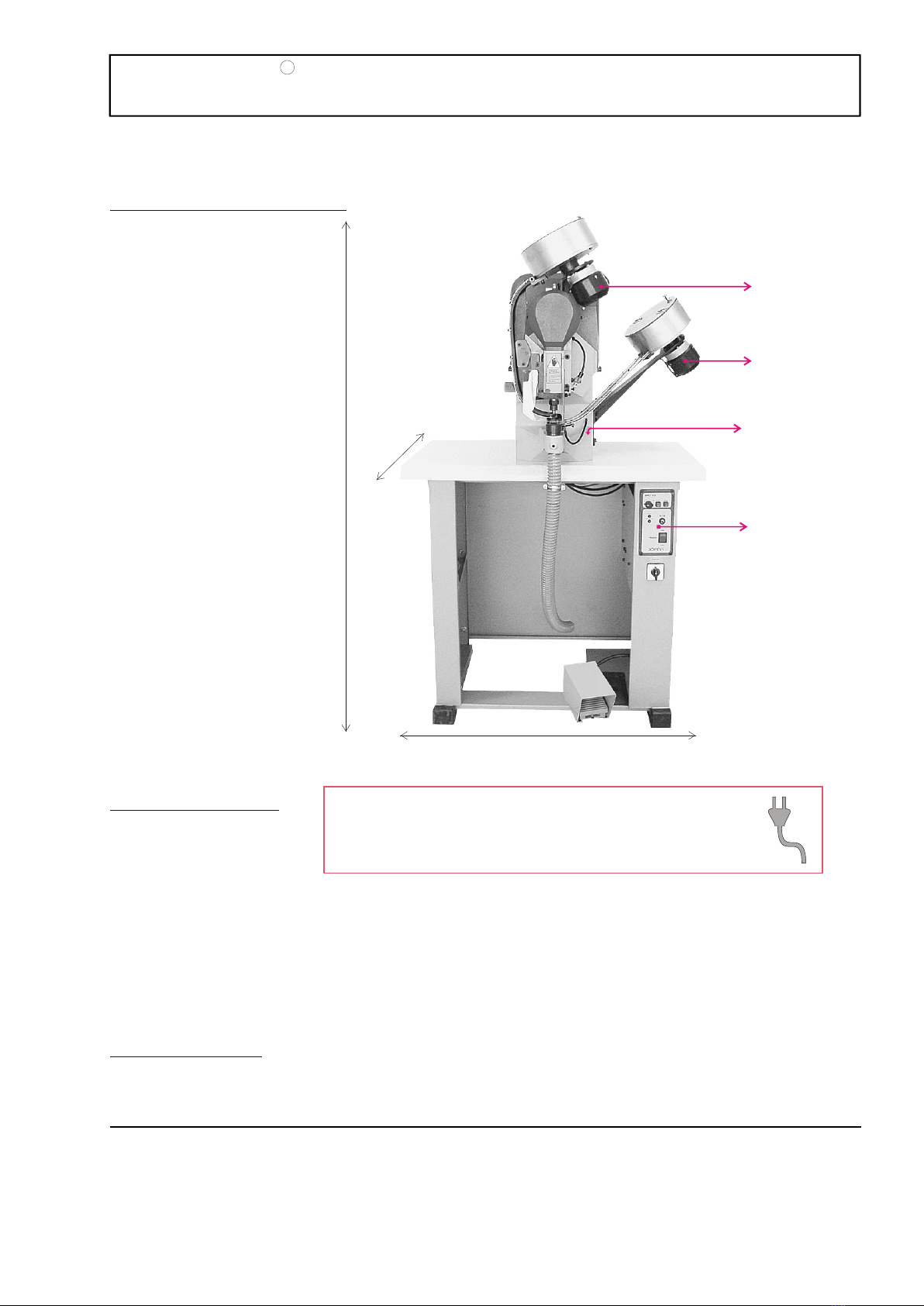
The J-239 model is an automatic electronic machine designed to set grommets with washers, grommets without
washers or to make holes in the material.
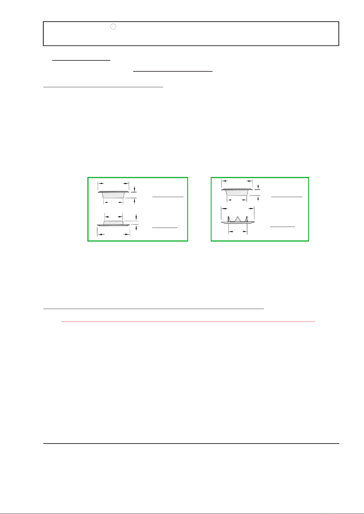
Each machine is manufactured for a specific size of grommet and washer. Grommet models may differ in: the
head size “D”, the lenght “L”, the interior diameter of tube “d”, the thickness, etc; and the washer models may differ
in: the exterior diameter “F”, the length “E”, the interior diameter of washer hole “i”, the washer shape, etc.
(the raceway and the top and bottom sets); but you always have to use the same
washer the machine was manufactured for.
In order for the machine to set different grommet models, certain parts need to be changed. SEE CHAPTER IV
ADJUSTMENTS.
JOPEVI, S.L. will accept no responsibility arising from the use of this machine in any way different from that which
is described in this instruction manual.
JOPEVI, S.L. RECOMMENDS YOU TO USE ALWAYS THE SAME TYPE OF GROMMET AND WASHER FOR
WHICH THE MACHINE WAS DESIGNED. In order for the machine to set different grommet and washer models,
certain parts need to be changed
Before starting the machine for the first time, and each time the location of the machine is changed, or any
changes are made in parts or any adjustments are done to it, we recommend the following steps:
After placing and making the machine level in its permanent location ,
lubricate it with SAE 40 type oil in the grease cups and red marks. Let the oil have enough time to cover the parts
and then clean the excess oil that might remain or drip.
To verify the machine is not blocked or might have suffered a blow or breakage, See figure 3 page 10:
“STILL WITHOUT PLUGGING IT IN”
1- Remove the cap nº 158 “pulley cover” that covers the flywheel by loosening the 4 allen screws that tighten it.
2- Rotate the flywheel nº 274 manually one cicle of 360º in the direction that the red arrow points (clockwise).
3- Verify that the machine is moving freely.
4- Put the cap on again (nº 158) and tighten it with the 4 allen screws.
PLEASE VERIFY THESE ADJUSTMENTS BEFORE CONNECTING THE MACHINE.
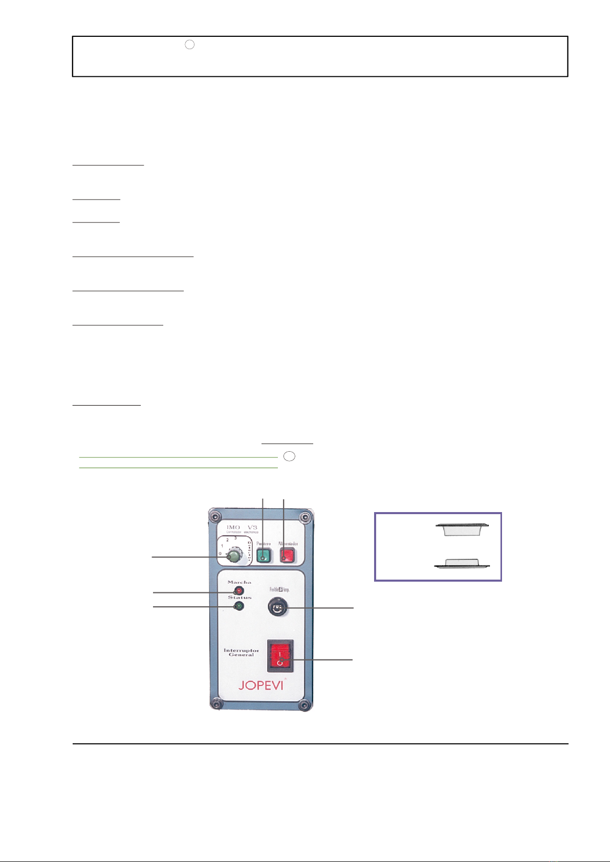
3.1. MACHINE DESCRIPTION.
3.2. SETTING UP THE MACHINE FOR ITS OPERATION.
MACHINE USES
GROMMET
WASHER
GROMMET
WASHER
DD
LL
FF
EE
DD
LL
FF
d
i
d
i
RMODEL J-239
JOPEVI
PAGE
9
The machine is equiped in the base with an electronic device “IMO V3” and a control panel described in figure 2,
showing the following features:
1- Main Switch: connects or disconnects all of the machine systems. When the switch is pushed towards the
symbol “I”, the led will light showing that the machine is “ON”.
2- Marcha: red led shows that the machine is connected and in stand-by mode.
3- Status: green led will light every time we press the pedal indicating that the machine is in operation. If
illuminated in a pulsating fashion, it indicates failure, disconnect the machine immediately.
4- Green pointer or switch: turns the lighted pointer on or off. Only in those machines equiped with this device
(optional).
5- Red switch or feeder: connects or disconnects the two 24V motors that make the grommets and washers
rotate in the deposits.
6- Washer detector: detects the flow of washers in the railing. When selected with the position “0”, it does not
detect the washers in the railing, and the machine may place only grommets or punch holes. When pulsated to the
outermost position “1”, it detects the washers, and will not allow to place the grommet without a washer or to
punch holes. The railing must have at least 8 washers for this feature to work properly.
The position" 2" and" 3" doesn't have application in this model of machine, we therefore will always indicate" 0" or
"1”.
7- 6 Amp fuse. Fuse holder. Uses a 6 amp fuse to protect the machine from high voltage.
Grommet
Washer
1
7
45
6
2
3
FIGURE 2
ELECTRONIC CONTROLLER “IMO V3”
Patented by JO PE VI.
R