J+J ILG/S User manual

MANUAL
FOR
INSTALLATION
AND
OPERATING
for the gearbox model ILG/S

ILG/S gearbox manual
J+J Deutschland GmbH, Auf der Hackelmasch 1, 31061Alfeld,
fon +4951816017, Fax.+4951816032
mail: info@juj-deutschland.de
homepage: www.juj-deutschland.de
2
1. Preface.........................................................................................................................................................................3
1.1 Technical data............................................................................................................................................................3
1.2 Handling and safety precautions.............................................................................................................................3
3. Adjustment of the stopscrews..................................................................................................................................6
4. Operating.....................................................................................................................................................................7
5. Maintenance...............................................................................................................................................................8

ILG/S gearbox manual
J+J Deutschland GmbH, Auf der Hackelmasch 1, 31061Alfeld,
fon +4951816017, Fax.+4951816032
mail: info@juj-deutschland.de
homepage: www.juj-deutschland.de
3
1. Preface
Rotork Gears bv produces gearboxes of different types and sizes. The ILG/S gearbox of Rotork Gears is a
sandwich manual override quarter turn gearbox for single acting actuators. It is intended to be used for the
manual operation of valves in pipelines, in case of failure of the of the automatic actuator system.
NB. This manual is valid only for the standard ILG/S gearboxes of Rotork Gears bv. For special versions, the
specifications and model can differ.
Rotork Gears bv is not responsible for any damage caused by incorrect use of the gearbox.
1.1 Technical data
Specifications
The maximum allowable input-and outputtorque are listedin table 1.
Gearbox connection to
actuator connection to
valve Max. Torque [Nm]
size ISO 5211 ISO 5211/1 Inputshaft Output
ILG/S 210 F05-F07 F05-F07-F10 28.5 330
ILG/S 550 F07-F10-F12 F07-F10-F12-F14
78 934
ILG/S 880 F10-F12-F14 F10-F12-F14-F16
123 1620
ILG/S 1250 F12-F14-F16 F10-F12-F14-F16
139 2640
ILG/S 1950 F16-F25 F12-F14-F16-F25
160 3050
ILG/S 1950 SP4
F16-F25 F12-F14-F16-F25
125 6800
ILG/S 6800 F25-F30 F16-F25-F30 160 4400
ILG/S 6800 SP4
F25-F30 F16-F25-F30 134 12500
ILG/S 250 SP4
F25-F30 F25-F30-F35-F40
142 32000
table 1: Connectiondata of the gearboxes
The Rotork Gears gearboxes can be used at ambient temperatures from –20 to +110°C.
For more specified information, you can contact our sales departement.
1.2 Handling and safety precautions
Be sure to read and understand this manual before installation and use of our ILG/S-gearbox.
Storage
The gearboxes need to be stored in a safe way to avoid accidents. Also avoid storage in areas subjected to high
temperature extremes and /or areas subjected to large amounts of humidity and dust.
Handling
Never drop the gearbox or otherwise subject it to strong impact.

ILG/S gearbox manual
J+J Deutschland GmbH, Auf der Hackelmasch 1, 31061Alfeld,
fon +4951816017, Fax.+4951816032
mail: info@juj-deutschland.de
homepage: www.juj-deutschland.de
4
Correct use
Prior to installation, be sure the gearbox willNOT be overloaded during normal use. For this, convince yourself
the valvesize and needed opening and closing torque do not exceed the values given for the gearbox. For the
maximum allowable torque of the gearbox, see table 1.
Rotork Gears bv is not responsible for any damage caused by incorrect use of the gearbox.
Installation en operating
Not observing and following the rules as stated in this manual can lead to damage and / or personal injuries. The
qualified personel must be fully aware of the instructions as descibed in this manual.
Only when the instructions are observed, correct operation of the gearboxes can be garanteed.
Disposal
Never refuse a gearbox at a general disposal unit. The gearbox has to be offered to a disposal depot for recycling.
The iron parts can be used for recycling . The seals are of nitrile and can be used for plastic recycling.
The grease may not be discharged to sewer-or surface water. It has to be disposed according to local regulations
for incineration.
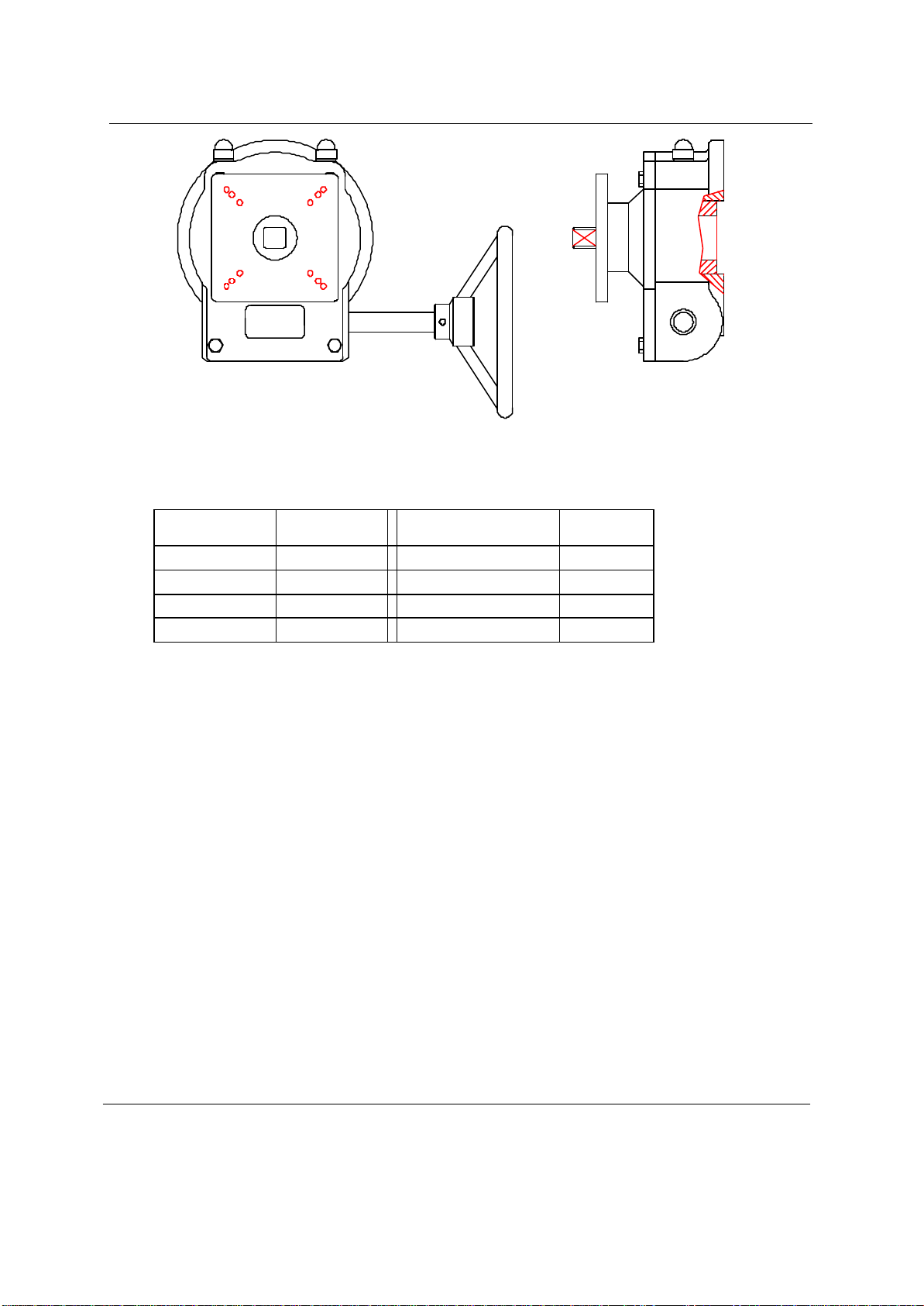
2. Installation : mounting to the valve
The ILG/S is a sandwich manual override quarter turn gearbox for single acting, quarter turn, pneumatic or
electric actuators.
For maximum allowable input-and outputtorque, refer to table 1 or the (not included) datasheet.
This manual describes the installation of the gearbox and its parts. The intention is to open a valve with the
gearbox in case of a failing actuator system. If the power supply fails the spring returns the actuator (and valve)
to the “secure” (closed) position.
1. The gearbox is standard delivered in closed position.
2. It is recommended to mount a handwheel on the inputshaft prior to assemble the gearbox to the valve.
3. Check if the boltcircle of the flanges (of gearbox and valve) coincide. Also check if the valvestem and
the bore of the driveshaft match.
4. Make sure the valve is in the fully closed position. If not, close the valve before continuing.
5. For fail-close actuators (90° clockwise close), the gearbox has to be positioned fully closed. This is
achieved by turning the handwheel clockwise.
6. In case of use of studbolts for fixing the gearbox to the valve, it is recommended to screw them into
the bottomflange of the gearbox prior to mounting the gearbox on top of the valve.
7. The use of a gasket between the flange of the valve and gearbox is recommended.

ILG/S gearbox manual
J+J Deutschland GmbH, Auf der Hackelmasch 1, 31061Alfeld,
fon +4951816017, Fax.+4951816032
mail: info@juj-deutschland.de
homepage: www.juj-deutschland.de
5
8. Put the driveshaft from the bottomside into the gearbox (see figure 1). The size and shape of the
connections of the driveshaft and the gearbox can differ from figure 1.
figure 1 : assembly of driveshaft into gearbox ILG/S
9. For fail-close actuators -clockwise close-be sure the driveshaft can make a free quarter turn clockwise
(seen from the bottomside) from its endposition; refer to figure 2 (the position of the 'free-run' can
differ from the figure). By this the gearbox can open the valve in case of actuator or power supply
failure.
figure 2 : Position of driveshaft.
10. Put the gearbox on top of the valve.
11. The gearbox is mounted perpendicular to the valve (see figure 3).
Table of contents