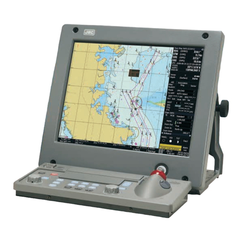
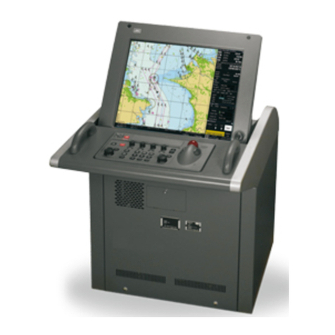
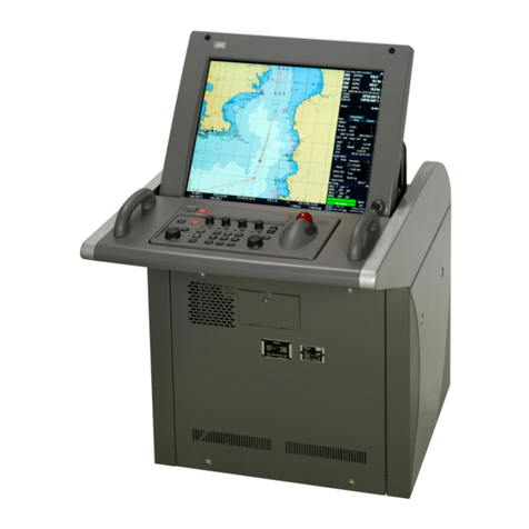
JRC J-Marine NeCST User manual

INSTRUCTIONINSTRUCTION
MANUALMANUAL
J-Marine NeCSTJ-Marine NeCST
ISO 9001, ISO 14001 Certified
MAR. 2020 Edition 3CODE No.7ZPSC0651
Not use the asbestos
For further information,contact:
URL Head office : http://www.jrc.co.jp/eng/
Marine Service Department
1-7-32 Tatsumi, Koto-ku, Tokyo 135-0053, Japan
:
+81-50-3786-9201
e-mail
One-call
JANJAN-470470-9ANN9ANN
JANJAN-470470-4ANN4ANN
JANJAN-470470-2ANN2ANN
JANJAN-470470-1PNN1PNN
JANJAN-470470-0ANN0ANN


i
z
Safety Cautions
z
Cautions for High Voltage
High voltages, ranging from several hundreds to tens of thousands of volts, are used in
electronic apparatus, such as radio and radar instruments. These voltages are totally harmless
in most operations. However, touching a component inside the unit is very dangerous. (Any
person other than authorized service engineers should not maintain, inspect, or adjust the unit.)
High voltages on the order of tens of thousands volts are most likely to cause instant deaths
from electrical shocks. At times, even voltages on the order of several hundred volts could lead
to electrocution. To defend against electrical shock hazards, don't put your hand into the inside
of apparatus. When you put in a hand unavoidably in case of urgent, it is strongly suggested to
turn off the power switch and allow the capacitors, etc. to discharge with a wire having its one
end positively grounded to remove residual charges. Before you put your hand into the inside of
apparatus, make sure that internal parts are no longer charged. Extra protection is ensured by
wearing dry cotton gloves at this time. Another important precaution to observe is to keep one
hand in your pocket at a time, instead of using both hands at the same time.
It is also important to select a secure footing to work on, as the secondary effects of electrical
shock hazards can be more serious. In the event of electrical shocks, disinfect the burnt site
completely and obtain medical care immediately.
Precautions for Rescue of Victim
of Electric Shock
When a victim of electric shock is found, turn off the power source and ground the circuit
immediately. If this is impossible, move the victim away from the unit as quick as possible
without touching him or her with bare hands. He or she can safely be moved if an insulating
material such as dry wood plate or cloth is used.
Breathing may stop if current flows through the respiration center of brain due to electric shock.
If the electric shock is not large, breathing can be restored by artificial respiration. A victim of
electric shock looks pale and his or her pulse may become very weak or stop, resulting in
unconsciousness and rigidity at worst. It is necessary to perform first aid immediately.
7ZPSC0651

ii
Emergency Measures
Method of First-Aid Treatment
Precautions for First-Aid
Treatments
Apply artificial respiration to the person who collapsed, minimizing moving as much as
possible avoiding risks. Once started, artificial respiration should be continued
rhythmically.
(1) Refrain from touching the patient carelessly as a result of the accident; the
first-aider could suffer from electrical shocks by himself or herself.
(2) Turn off the power calmly and certainly, and move the patient apart from the cable
gently.
(3) Call or send for a physician or ambulance immediately, or ask someone to call
doctor.
(4) Lay the patient on the back, loosening the necktie, clothes, belts and so on.
(5) (a) Feel the patient's pulse.
(b) Check the heartbeat by bringing your ear close to the patient's heart.
(c) Check for respiration by bringing your face or the back of your hand to the
patient's face.
(d) Check the size of patient's pupils.
(6) Opening the patient's mouth, remove artificial teeth, cigarettes, chewing gum, etc.
if any. With the patient's mouth open, stretch the tongue and insert a towel or the
like into the mouth to prevent the tongue from being withdrawn into the throat. (If
the patient clenches the teeth so tight that the mouth won't open, use a
screwdriver or the like to force the mouth open and then insert a towel or the like
into the mouth.)
(7) Wipe off the mouth to prevent foaming mucus and saliva from accumulating.

iii
Treatment to Give When the Patient Has
a Pulse Beating but Has Ceased to
Breathe
∗Performing mouth-to-mouth artificial respiration
(1) Bend the patient's face backward until it is directed to look back. (A pillow may
be placed under the neck.)
(2) Pull up the lower jaw to open up the airway. (To spread the airway)
(3) Pinching the patient's nose, breathe deeply and blow your breath into the
patient's mouth strongly, with care to close it completely. Then, move your
mouth away and take a deep breath, and blow into his or her mouth. Repeat
blowing at 10 to 15 times a minute (always with the patient's nostrils closed).
(4) Continue artificial respiration until natural respiration is restored.
(5) If the patient's mouth won't open easily, insert a pipe, such as one made of
rubber or vinyl, into either nostril. Then, take a deep breath and blow into the
nostril through the pipe, with the other nostril and the mouth completely closed.
(6) The patient may stand up abruptly upon recovering consciousness. Keep the
patient lying calmly, giving him or her coffee, tea or any other hot drink (but not
alcoholic drink) to keep him or her warm.
Mouth-to-mouth artificial respiration with the patient's head lifted
[1]
(1) Lift the back part of the patient's
head. Support the forehead with
one of your hand and the neck
with the other hand.→[1].
Many patients will have their
airways opened by lifting their
head in this way to ease
mouth-to-mouth artificial
respiration.
[2]
(2) Closing the patient's mouth with
your mouth, press your cheek
against the patient's nose→[2].
Alternatively, hold the patient's
nose with your finger to prevent
air leak
→[3].
[3]
(3) Blowing air into the patient's
lungs. Blow air into the patient's
lungs until chest is seen to rise.
The first 10 breaths must be
blown as fast as possible.
Fig. 1 Mouth-to-mouth artificial respiration

iv
Flow of Cardiopulmonary Resuscitation (CPR)
Breathing
Recovery position
- Lay the injured or ill
person on his/her
side and wait for the
arrival of the
emergency services.
Ask for help.
- Make an emergency call.
-
Ask to bring an AED.
Not breathing or do not know whether the person is breathing
A person is collapsing.
- Secure the safety of the surrounding area.
- Prevent secondary disasters.
Check for response.
-
Call while tapping the shoulder.
Confirmation of breathing and judgment of
cardiac arrest.
-
Check for breathing.
Listen to the appeal of the
injured or ill person and give
the necessary first-aid
Arrival of an AED
- Turn on the power.
- Use theAED by following its voice prompts.
Fitting of the electrode pads, etc.
Responding
Automatic electrocardiogram
analysis
- Do not touch the injured or ill
person.
Electric shock is needed.
Electric shock is not needed.
Delivery of electric shock
When the injured or ill
person has been
handed over to the
emergency services or
has started moaning or
breathing normally, lay
him/her on his/her side
in a recovery position
and wait for the arrival
of emergency services.
Not responding or do not know
Resume CPR from chest
compressions by following the
voice prompts of the AED.
When to
stop CPR
Chest compressions
- Strong pressure as the chest sinks about 5 cm
- Speed of compression 100-120 times per minute
Combination of chest compression and artificial
respiration Note(1)
- Rescuers who are not trained will only perform
chest compressions. See Note (1) for details
Note(1) Combination of chest compression
and artificial respiration
-
Untrained rescuers will only perform chest
compressions.
-
If the rescuer is trained in artificial
respiration and has the skills and intention
to perform artificial respiration, perform
chest compressions and artificial respiration
at a ratio of 30: 2 times. If you are
concerned about infection, use protective
equipment: mouthpiece for artificial
respiration.
A person is collapsing.
- Secure the safety of the surrounding area.
- Prevent secondary disasters.
The AED
automatically
analyzes the
heart rhythm
every 2 min.
If call emergency, can
receive judgment on cardiac
arrest and guidance for cardiopulmonary resuscitation

v
Specific Procedures for Cardiopulmonary Resuscitation (CPR)
1. Check the scene for safety to prevent secondary disasters
a) Do not touch the injured or ill person in panic when an accident has occurred. (Doing so may
cause electric shock to the first-aiders.)
b) Do not panic and be sure to turn off the power. Then, gently move the injured or ill person to a
safe place away from the electrical circuit.
2. Check for responsiveness
a) Tap the shoulder of the injured or ill and shout in the ear saying, "Are
you OK?"
b) If the person opens his/her eyes or there is some response or
gesture, determine it “s "responding." But, if there is no response or
gesture, determine it “s "not responding."
3. If responding
a) Give first-aid treatment.
4. If not responding
a) Ask for help loudly. Ask somebody to make an emergency call and bring an AED.
• Somebody has collapsed. Please help.
• Please call an ambulance.
• Please bring an AED.
• If there is nobody to help, call an ambulance yourself.
5. Check for breathing
a) Check the his/her chest and abdomen rise and fall.
b) If the injured or ill person is breathing, place him/her in the recovery position and wait for the
arrival of the emergency services.
• Turn his/her body sideways.
Please call an
ambulance. Please bring an AED.
Are you OK?

vi
6. Cardiopulmonary resuscitation (CPR) (combination of chest compressions and
rescue breaths)
a) Chest compressions
1) Position of chest compressions
• Position the heel of one hand in the center of the chest, approximately between the
nipples, and place your other hand on top of the one that is in position.
2) Perform chest compressions
• The speed of compression is about 100-120
times per minute, 30 times continuously,
stretching the elbow continuously and
compressing vertically.
• With each compression, depress the chest
wall to a depth of approximately about 5 cm.
b) Combination of 30 chest compressions and 2 rescue breaths
1) Untrained rescuers will only perform chest compressions.
2) If the rescuer is trained in artificial respiration and has the skills and intention to perform
artificial respiration, perform chest compressions and artificial respiration at a ratio of 30: 2
times.
3) If you are concerned about infection, use protective equipment: mouthpiece for artificial
respiration.
4) Continuously perform the combination of 30 chest compressions and 2 rescue breaths
without interruption.
5) If there are two or more first-aiders, alternate with each other approximately every two
minutes (five cycles of compressions and ventilations at a ratio of 30:2) without interruption.
Compress
with these
parts (the
heels of
both hands).
30 times
2 times
CPR mask
Mouthpiece for rescue
breathing

vii
7. When to stop cardiopulmonary resuscitation (CPR)
a) When the injured or ill person has been handed over to the
emergency services
b) When the injured or ill person has started moaning or breathing
normally, lay him/her on his/her side in a recovery position and wait
for the arrival of emergency services.
8. Arrival and preparation of an AED
a) Place the AED at an easy-to-use position. If
there are multiple first-aiders, continue CPR
until the AED becomes ready.
b) Turn on the power to the AED unit. Depending
on the model of the AED, you may have to
push the power on button, or the AED
automatically turns on when you open the
cover.
c) Follow the voice prompts of the AED.
9. Attach the electrode pads to the injured or ill person's bare chest
a) Remove all clothing from the chest, abdomen, and arms.
b) Open the package of electrode pads, peel the pads off and securely
place them on the chest of the injured or ill person, with the adhesive
side facing the chest. If the pads are not securely attached to the chest,
the AED may not function. Paste the pads exactly at the positions
indicated on the pads, If the chest is wet with water, wipe dry with a dry
towel and the like, and then paste the pads. If there is a pacemaker or
implantable cardioverter defibrillator (ICD), paste the pads at least 3cm
away from them. If a medical patch or plaster is present, peel it off and
then paste the pads. If the injured or ill person's chest hair is thick, paste
the pads on the chest hair once, peel them off to remove the chest hair,
and then paste new pads.
c) Some AED models require to connect a connector by following voice
prompts.
d) The electrode pads for small children should not be used for children
over the age of 8 and for adults.
10. Electrocardiogram analysis
a) The AED automatically analyzes electrocardiograms. Follow the
voice prompts of the AED and ensure that nobody is touching the
injured or ill person while you are operating the AED.
b) On some AED models, you may need to push a button to analyze the
heart rhythm.
Turn on the power.
viii
11. Electric shock (defibrillation)
a) If the AED determines that electric shock is needed, the voice prompt
saying, "Shock is needed" is issued and charging starts
automatically.
b) When charging is completed, the voice prompt saying, "Press the
shock button" is issued and the shock button flashes.
c) The first-aider must get away from the injured or ill person, make sure
that no one is touching him/her, and then press the shock button.
d) When electric shock is delivered, the body of the injured or ill person
may jerk.
12. Resume chest compressions
a) Resume chest compressions according to AED voice message.
・Strong pressure as the chest sinks about 5 cm
・Speed of compression 100-120 times per minute
13. Automatic electrocardiogram analysis
a) When 2 minutes have elapsed since you resumed cardiopulmonary resuscitation (CPR), the
AED automatically analyzes the electrocardiogram.
b) If you suspended CPR by following voice prompts and AED voice prompt informs you that
shock is needed, give electric shock again by following the voice prompts.
If AED voice prompt informs you that no shock is needed, immediately resume CPR.
14. When to stop CPR (Keep the electrode pads on.)
a) When the injured or ill person has been handed over to the emergency services
b) When the injured or ill person has started moaning or breathing normally, lay him/her on his/her
side in a recovery position and wait for the arrival of emergency services.
Press the shock button.

ix
PREFACE
Thank you for purchasing our JAN-470 series equipment.
The JAN-470 series are navigation support equipment for ship with the following
functions.
(1) To draw and zoom in/out an electronic navigation chart (ENC)
(2) Similar operation on an ENC to writing by hand on a paper chart
(3) To create a route while seeing handwritten data
(4) Information can be shared between the ship and land, and the ship's operation
status can be checked on the land side.
(5) Daily work management during port departure/entry
(6) Enable information sharing between ship and shore management center when
emergency occurs
(7) To display weather and sea conditions, to support safe navigation
• For the best operation, read this manual thoroughly before use.
• Keep this manual in a convenient place for future reference. Make use of this
manual when experiencing operation difficulties.
• An LCD panel is used for the monitor of this equipment. Please note that
although the LCD panel is manufactured with very high precision techniques,
some defective pixels may occur. It should be noted that the ratio of the
number of effective dots of the LDC panel is 99.9994% or higher. Use this
equipment as navigation aid to the last.
• Use the created route after checking in ECDIS.
• The contents of this device might be change without notice in the future.

x
ABOUT COPYRIGHT
[Hatteland Technology AS]
This user manual is based on the original copyright protected document from Hatteland Technology AS
– Eikeskogvegen 52 - Aksdal. "Japan Radio Co., Ltd." is fully responsible for the content of this
document, and Hatteland Technology holds no responsibility for this content
[Schneider Electric SA]
© 2015 Schneider Electric. All Rights Reserved. Schneider Electric and APC are trademarks owned by
Schneider Electric Industries SAS or its affiliated companies.

xi
Pictorial Indication
Meanings of Pictorial Indication
Various pictorial indications are included in this manual and
are shown on this equipment so that you can operate them
safely and correctly and prevent any danger to you and / or to
other persons and any damage to your property during
operation. Such indications and their meanings are as
follows.
Please understand them before you read this manual:
DANGER This indication is shown where incorrect equipment
operation due to negligence may cause death or serious
injuries.
WARNING This indication is shown where any person is supposed to
be in danger of being killed or seriously injured if this
indication is neglected and these equipment are not
operated correctly.
CAUTION
This indication is shown where any person is supposed to
be injured or any property damage is supposed to occur if
this indication is neglected and these equipment are not
operated correctly.
Examples of Pictorial Indication
Electric Shock
The mark represents CAUTION
(including DANGER and WARNING).
Detailed contents of CAUTION ("Electric
Shock" in the example on the left) is
shown in the mark.
Disassembling
Prohibited
The mark represents prohibition.
Detailed contents of the prohibited action
("Disassembling Prohibited" in the
example on the left) is shown in the mark.
Disconnect
the power plug
!
The mark represents instruction.
Detailed contents of the instruction
("Disconnect the power plug" in the
example on the left) is shown in the mark.
!
!
!

xii
Precautions upon Equipment Operation
DANGER
Never attempt to check or repair the inside of the equipment.
Check or repair by an unqualified person may cause fire or electric shock.
Contact our head office, or a nearby branch or local office to request servicing.
Never remove the cover of this equipment. Removing it causes a risk of touching the
internal high-voltage part to lead to electric shock.
Do not attempt to disassemble or tamper with this equipment. Otherwise, fire, electric
shock, or malfunction may occur.
When performing maintenance of the equipment, make sure to turn off the main
power supply. Failure to do so may result in electric shock.
Make sure to turn off all the main power supplies before cleaning the equipment.
Since voltage is output from the rectifier, failure to observe this instruction may result
in equipment failure, or death or serious injury due to electric shock.
For internal inspection and repair, contact our sales department or local branch,
branch, sales office or agency.

xiii
WARNING
When performing maintenance work, make sure to turn off the power so that the
power supply to the equipment is completely cut off. Some equipment components
can carry electrical current even after the power switch is turned off, and thus
performing maintenance work without completely cutting off the power supply may
result in electric shock, equipment failure, or accidents.
When cleaning the touch panel display unit, do not use wax, thinner, etc. Failure to
observe this instruction may result in damage to the LCD panel surface of the touch
panel display unit.
Also, do not use chemicals, such as alcohol or antiseptic. Failure to observe this
instruction may cause change in luster or color, or color fade-out.
When reading from or writing to a file in a USB flash memory, confirm computer
viruses do not exist in the USB flash memory in advance. If the processor unit is
infected with viruses, it influences other equipment, which may cause breakdown.
Do not remove a USB flash memory while its access lamp is flashing. Data may be
damaged when the USB flash memory is inserted or removed while accessing it,
and it may cause breakdown.
When reading from or writing to a file in an external storage media, confirm
computer viruses do not exist in the external storage media in advance. If the
processor part is infected with viruses, it influences other equipment, which may
cause breakdown.
If foreign objects such as water or metal should get inside the equipment, turn off
the power switch of the equipment, turn off the main power, and then contact our
head office, or a nearby branch or local office to request servicing. Continued use of
the equipment may cause fire, electric shock, or malfunction.
If you find abnormalities, such as smoke, unusual odor, or extremely high heat
coming from the equipment, turn off the power switch and the main power supply,
and then contact our head office, or a nearby branch or local office to request
servicing. Continued use of the equipment may cause fire or electric shock.
When switching Day/Night, particularly switching to [Night], recognition of display
information may be hindered. Confirm that you can recognize display information.
Arrange and use the components of the power supply specification taking into
consideration the ship’s mains power supply.
The specification voltage of JAN - 470 series components is AC 100 V or AC 230 V.
A voltage-dropping transformer is needed in some cases, for example, for 440 VAC.
Improper arrangement or usage may cause fire or accidents.

xiv
CAUTION
Use J-Marine NeCST only as a navigation aid.
When using a created route, be sure to first check it by ECDIS, and then use the
route.
J-Marine NeCST does not necessarily match with the safety check result of the route
at ECDIS because it performs simplified route safety check.
Use J-Marine NeCST only as a navigation aid.
J-Marine NeCST divides a chart into multiple tiles and draws them. For this reason,
chart objects are sometimes drawn separately.
The Conning block of J-Marine NeCST outlines the information displayed on the
Conning product. For details of a variety of ship’s information, check the Conning
product.
Do not use or leave the equipment under direct sunlight for a long time or at
temperatures of 55°C or higher. Otherwise, fire or malfunction may occur.
Do not place glasses or cups containing water, etc., or small metal objects on this
equipment. If water or such objects get inside, fire, electric shock, or malfunction may
occur.
Do not touch the equipment with hands or gloves wet with fresh water or seawater.
Otherwise, electric shock or other troubles may occur.
• Do not place objects that scratch on the display.
• Placing hot objects on the display may cause deformation of the display.
• Do not apply any undue shock on the display. Otherwise, malfunction may occur.
Be sure to turn off the main power supply before inspection or replacement of parts.
Otherwise, electric shock, fire, or malfunction may occur.

xv
Glossary
AIS : Automatic Identification System.
AIO : Admiralty Information Overlay published by United Kingdom
Hydrographic Office (UKHO)
AtoN : Aids to Navigation
Base CD : Chart CD containing complete chart data
BFT : Beaufort scale of wind force
BRG : Bearing
Capt’s DOSCA : Communication system between ship and shore provided by
Weathernews Inc. aimed at safety, economy and environmental
operation (Captain’s Dynamic Operation System for Counter planning
and Analysis).
Cell Permit : A file containing an encryption key for S-63 chart. This file is supplied by
UKHO, PRIMAR STAVANGER, and Hydrographic and Oceanographic
Department of Japan Coast Guard.
ENC Decoder : Software used to manage charts. This software imports/updates charts.
COG : Course Over the Ground
CTW : Course Through Water. The direction of the ship's movement through
the water.
Data Server : S-63 chart supply source
DNV GL : Det Norske Veritas - Germanischer Lloyd
ECDIS : Electronic Chart Display and Information System
ENC : Electronic Navigational Chart S-57/S-63
ETA : Estimated Time of Arrival
ETD : Estimated Time of Departure
GC : Great Circle
GPS : Global Positioning System
HDG : Heading. Ship’s heading
HSC : High Speed Craft. Vessels conforming to the definition of High Speed
Craft in SOLAS
H UP : Head up. In H UP mode, own ship’s heading line is always pointed to the
top center of the radar display.
IHO : International Hydrographic Organization
IMO : International Maritime Organization
J-Marine Box App : JRC app to collect data in ship
LMT : Local Mean Time
MFD : Multi-Function Display. Each navigation support function such as
RADAR, ECDIS, Conning, or AMS can be executed by switching.
MMSI : Maritime Mobile Service Identity
NAVTEX : Navigational Telex
NeCST : Navigational electronic Conning Station Table
NeCST Manager : Land side equipment for sharing information with NeCST
NM : Nautical Mile 1 nm = 1852 m
NMEA : Protocol used for communication of navigation equipment

xvi
PRIMAR STAVANGER : A Norwegian company supplying charts. Publisher of S-63 encrypted
charts
REV : Revolution
RL : Rhumb Line
RM : Relative Motion. A representation where the own ship position remains
fixed and all targets move relative to own ship.
RMS : JRC's original system for diagnosing the operational status of JRC ship
equipment from land.
ROT : Rate Of Turn. Amount of turning per unit time
Route : A set of waypoints
S-57 : IHO transfer standard for digital hydrographic data
S-63 : IHO data protection scheme
SA Certificate file : An electronic file certifying the supplier of S-63 charts. This file is needed
to import/update S-63 charts.
SENC : System Electronic Navigational Chart
SOG : Speed Over the Ground
SAR : Search And Rescue
SART : Search And Rescue Transponder
SPD : Speed
STW : Speed Through Water
StormGeo : Norway-based global provider of weather intelligence
Smart Ship Viewer : JRC's corporate service for managing ship information from the shore
SSV Mobile : An application for linking ships and lands for smartphones.
Downloadable from the App Store.
TM : True Motion. A representation where own ship and targets move
according to their motion
TTG : Time To Go. Time needed to go to the next waypoint
Vector : Displays the vector length of other ships.
UKHO : United Kingdom Hydrographic Office
Update CD : Chart CD containing only the chart data updated from Base CD. This CD
can be used when Base CD data has been imported.
USER CODE : A user-specific code assigned by JRC. This cord is required when using
ARCS and S-63 charts.
UTC : Universal Time, Coordinated
VDR : Voyage Data Recorder
WP : Waypoint
XTD : Cross track distance
Import (ENC Decoder) : A procedure of enabling the chart supplied on Base CD to be displayed
on NeCST
Voyage data : Data used to manage routes and handwritten data for each voyage
Hydrographic and Oceanographic Department:
Hydrographic and Oceanographic Department of Japan Coast Guard.
Publisher of ENC
Update (ENC Decoder) : A procedure of applying the update data supplied on Update CD to the
imported chart
Scale : Display scale
Spot depth : Numeric representation of depth

xvii
Leg : Line between two consecutive waypoints
Divider : Compass. This can be used to measure the distance and bearing
between any two points.
Ruler : Scale. This can be used to measure any distance and angle.
Paper weight : This can manage the chart moving mode and handwriting mode.
Chart moving mode : Mode used to move the drawing position of the chart
Handwriting mode : Mode to fix and write in the chart
Navplan : Function to transition to the voyage data screen
Chart : Function to move to the own ship position
Draw : Function for handwriting. This enables the user to write freely, for
example, NGA on the chart.
Tool : An aid tool for route planning
Measure : Measures distances between points. This enables measurement and
comparison of distances for any ship speed.
Circle : Creates range markers. This enables setting of any distance (radius) and
its measurement and comparison.
Loupe : Loupe function. This enables display of the latitude/longitude and chart
information of any place.
Sticker : Places a sticker as information to record.
Template : Template that can be placed on the chart
Memo : Enables the user to tell the next user a message for him/her or an
instruction from the captain when relieved of watch.
Photo : Function to display photos. This enables check of uploaded photos.
Sea View : Displays icons on the chart in conjunction with the information of the
photo position and bearing.

xviii
CONTENTS
Safety Cautions ................................................................................................. i
Emergency Measures ...................................................................................... ii
Flow of Cardiopulmonary Resuscitation (CPR).................................................... iv
PREFACE ................................................................................................................ ix
ABOUT COPYRIGHT ................................................................................................ x
Pictorial Indication .......................................................................................... xi
Precautions upon Equipment Operation ...................................................... xii
Glossary ............................................................................................................... xv
CONTENTS........................................................................................................... xviii
Section 1 Overview.............................................................................................. 1-1
Section 2 Components........................................................................................ 2-1
Default Supply List .................................................................................................................2-1
Optional Supply List ...............................................................................................................2-2
Default Components – External View ....................................................................................2-3
2.3.1 Touch Panel Display unit – External View ........................................................................2-3
2.3.2 Display Processing Unit – External View..........................................................................2-5
2.3.3 Data Processing Unit – External View..............................................................................2-8
2.3.4 JUNCTION BOX – External View.....................................................................................2-9
Optional Components – External View ................................................................................2-10
2.4.1 UPS – External View ......................................................................................................2-10
2.4.2 JB CONTROL BOX – External View ..............................................................................2-14
2.4.3 Sensor LAN Switch unit – External View........................................................................2-16
2.4.4 SLC – External View.......................................................................................................2-19
2.4.5 26-inch desktop frame – External View..........................................................................2-20
Model list ..............................................................................................................................2-21
Connection Diagram.............................................................................................................2-22
2.6.1 Connection diagrams [JRC]............................................................................................2-22
2.6.2 Connection diagrams [FURUNO] ...................................................................................2-29
Section 3 Basic Operations ................................................................................ 3-1
3.1 Name and Function of Each Unit ...........................................................................................3-1
3.1.1 Touch panel display unit ...................................................................................................3-1
46 inch touch panel display unit (NWZ-1470/1470N) ................................................3-1
26 inch touch panel display unit (NWZ-208)..............................................................3-2
3.1.2 Display Processing Unit....................................................................................................3-3
Display Processing Unit (NWM-1470) .......................................................................3-3
Display Processing Unit (HNS-00010).......................................................................3-3
3.1.3 Data Processing Unit........................................................................................................3-4
Data Processing Unit (NJW-1460).............................................................................3-4
3.2 Powering ON and Starting......................................................................................................3-5
3.3 Setting Voyage Data ..............................................................................................................3-7
3.3.1 Creating New Voyage Data ..............................................................................................3-7
3.3.2 Using navigation data from Smart Ship Viewer..............................................................3-12
3.3.3 Selecting Existing Voyage Data......................................................................................3-15
3.3.4 Deleting Voyage Data.....................................................................................................3-16
3.4 Main Functions of Top Screen .............................................................................................3-17
3.4.1 Scale Display..................................................................................................................3-18
3.4.2 Own Ship Information .....................................................................................................3-19
3.4.3 Setting ship’s O’clock......................................................................................................3-19
3.4.4 Chart Display Setting......................................................................................................3-20
3.4.5 Screen Shot....................................................................................................................3-21
Capturing Screen Shot.............................................................................................3-21
This manual suits for next models
5
Table of contents
Other JRC Car Navigation System manuals
Popular Car Navigation System manuals by other brands

Kia
Kia Sorento owner's manual

Magellan
Magellan Maestro 5310 - Automotive GPS Receiver user manual

Blaupunkt
Blaupunkt CAPE TOWN 945 operating instructions

GMC
GMC 2004 YUKON DENALI user manual

Magellan
Magellan Magellan eXplorist 300 Instructions for operating

Volvo
Volvo Car navigation system instruction manual