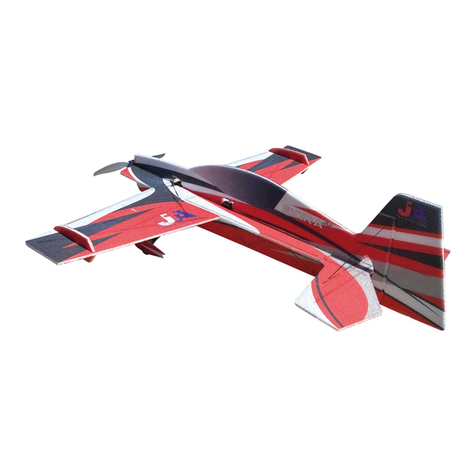
JTA Innovations Yak 54 User manual

www.modellmarkt24.ch
JTA Innovations ” Yak
www.modellmarkt24.ch

www.modellmarkt24.ch
Please Read For Your Safety
The poduct that ou hae eceied is not a to. Please undestand that model
aicaft hae seeal moing pats and euipment that if misused, can not onl
cause ham to othe mateials and objects, but also to ou and othes aound
ou. JTA Innoations is not accountable o esponsible fo an eents o
incidents that cause damage, inju, o een death. Afte puchase and
eceiing of this poduct, the custome is full esponsible fo the assembl
and use of the model. We cannot monito the pocedue/methods used in
assembling o fling of the model. If opeating in the United States, please
make sue that ou hae membeship ith the Academ of Model Aeonautics
and follo AMA ules. Please opeate the model at AMA fling sites. If liing
outside of the US, please follo the ules of model aiation opeation in ou
egion. JTA Innoations is not esponsible fo an disegad o beaking of
these ules. Pio to being shipped to each custome, aifames ill be checked
fo an damages. We hae no contol oe hat happens duing the shipping
pocess. If an poduct is deemed defectie b a custome, please contact JTA
Innoations ith poof of defect most likel photo o ideo, and poof of
puchase including puchase date. JTA Innoations ill analze ou claim and
handle the situation case b case.
www.modellmarkt24.ch

www.modellmarkt24.ch
We are pleased to introduce the first development of the
JTA Innovations line of foamies, the 32” Yak 54. The Yak
has always been a popular and classic platform within the
RC aerobatic community. Designed with all styles of foamy
flying in mind, the Yak is constructed with 6mm EPP which
allows for controllable outdoor flying as well as nimble
indoor flying. Equipped with an extremely rigid carbon fiber
arrangement, state of the art hardware, durable and
efficient landing gear, and flexible yet strong EPP foam, the
Yak is sure to withstand the most demanding of flights.
Along with the superb flight characteristics and high quality
construction, the Yak is available in 2 printed color schemes
designed by Matt Stringer.
Weight: Approximately 175-180g without battery
Required:
Motor - Hacker A10-9L or equivalent/similar
ESC - 10 to 15 amp ESC
Servos - 4g-12g servos (Qty. 3)
Propeller- 8-9” electric (APC highly recommended)
www.modellmarkt24.ch

www.modellmarkt24.ch
Tools/Supplies needed
Including but not limited to:
-Ruler
-Foam safe CA or preferred glue for construction and regular CA for
linkages
-Hobby knife with blades
-Scissors
-Heat gun or lighter for heat shrink
-Assorted phillips and flat blade screwdrivers
-Assortment of small drill bits
-Drill
-Needle nose pliers
-Driver set
-90 degree square
-CA accelerator
-Sandpaper
www.modellmarkt24.ch

www.modellmarkt24.ch
* Belo ae photos of the ne constuction esion fo efeence. This eplaces
some featues aileon gusset bacing fo eample that ae listed late on in
the manual. If ou ae assembling an olde esion, please moe on to the
manual hee the contol suface beak in begins.*
www.modellmarkt24.ch

www.modellmarkt24.ch

www.modellmarkt24.ch

www.modellmarkt24.ch
In order to get consistent full range of all control surfaces during flight and
setup, we recommend that the first thing you do after unboxing is weighing
down the control surfaces as shown above. Each surface will take about
www.modellmarkt24.ch

www.modellmarkt24.ch
60-120 minutes to complete, then you will notice that it will be easier to move
the surface to full deflection.
Now, locate the horizontal piece of the fuselage as well as
both wings. Make sure the fuselage is flat inverted and test
fit each wing panel. After test fitting, you can now proceed to
glueing in the wings to match up with the cutouts in the
fuselage. We recommend using a sheet of wax paper or
parchment paper to avoid the airplane becoming glued to
the workbench.
www.modellmarkt24.ch

www.modellmarkt24.ch
Now that the wing is glued, locate the wing spar. This is the
square carbon fiber that will be the length of the wing itself.
Test fit into the slot in the wing and make sure it is flush
even at the spots where the wing joins with the fuse. Once
this is done, you can then glue the spar in. Make sure that it
is not sticking out passed the wing on either side.
Next, provide support for the aileron counterbalances by
locating the 95mm long flat piece of carbon fiber. You will
www.modellmarkt24.ch

www.modellmarkt24.ch
notice there is a cutout for this piece. Test fit, glue, then
repeat for the other aileron.
Locate the triangular joiner that will be placed on the
underside of each aileron. Once you make sure that it fits
clean and snug into the cutout, you can glue this piece in and
repeat to the other side.
With the joiner in place, you can now begin the process of
bracing the aileron. This will include four carbon fiber rods
in the configuration shown above. The lengths for each are
190mm, 170mm, 140mm, and 155mm. The carbon rods will
www.modellmarkt24.ch

www.modellmarkt24.ch
be pre-cut. You may also be able to spot the black dots
where carbon can be referenced for placing. Be sure to
provide a good connection for the carbon by poking through
the foam.
Test fit the horizontal stab/elevator into the rear of the
fuselage. If all is well, glue into place making sure that it is
flush with the fuselage and flat with the rest of the airplane.
Locate the carbon fiber elevator spar. It will be square just
as the wing spar is and cut to fit the cutout in the elevator.
Length will be 400mm.
www.modellmarkt24.ch

www.modellmarkt24.ch
Making sure that everything is 90 degrees and flat, it is
important to test fit the underneath side of the vertical
fuselage. The fit should be fairly snug, so do not glue any
spots until you know that each tab will be inserted fully
along the fuse. Once this is complete, you can then apply
glue along the edges. When placing back in, once again make
sure that it is adjusted at 90 degrees to the rest of the
airframe. There is no need to apply glue to the edges that
will cover the servos.
www.modellmarkt24.ch

www.modellmarkt24.ch
As shown in the photo above, a flat piece of carbon fiber will
be used for the tailwheel purpose and allow the aircraft to
rest and taxi on the ground without coming in contact with
the foam. This will be glued to the bottom vertical piece of
the fuselage. The length of this piece is 60mm.
www.modellmarkt24.ch

www.modellmarkt24.ch
Shown above is the entire assembly for the landing gear. The
square carbon fiber landing gear is already glued into the
axles. You will find the wheels as well as three total collars (2
foam pieces, and 1 wood/carbon laminated piece).
www.modellmarkt24.ch

www.modellmarkt24.ch
Along with the EPP wheel spat, there is an additional piece
of EPP that is the same shape that will be glued together to
provide strength for the rear part of the spat. The photo
above shows the two pieces glued together.
www.modellmarkt24.ch

www.modellmarkt24.ch
The wheel spat will be the first thing that is put on the axle.
This will go all the way flush to the landing gear/axle joiner.
Add a drop of glue to put this into place once it is positioned
to your desire.
Next will be sliding on the larger foam collar. Add just a
small amount of glue to hold this into place against the wheel
spat.
www.modellmarkt24.ch

www.modellmarkt24.ch
Now, the tire/wheel is ready to be placed on the axle. Do not
add any glue so that it can rotate freely around the axle.
Next, slide on the smaller piece of foam that will act as the
collar on the outside of the wheel. Once again, do not add
any glue to this piece.
www.modellmarkt24.ch

www.modellmarkt24.ch
Lastly, apply the small wooden collar that will hold the
wheel onto the axle. You can add a small drop of glue to
ensure that this piece will not slide off.
Pictured above is the landing gear mounted on the airplane.
You will notice that each landing gear side is crossed
through to the opposite side of the airplane. You should be
able to find two slices in the vertical fuse that will indicate
where the carbon landing gear will slide through. Make sure
www.modellmarkt24.ch

www.modellmarkt24.ch
that the landing gear positioning is correct to allow the
airplane to sit level on the ground. Once this is confirmed,
you can then glue in the carbon fiber into the opposite sides
of the wing as well as where the two pieces of the landing
gear join in the fuse.
Now, you can apply the foam landing gear covers. Once you
make sure that the carbon fiber rod of the landing gear is
fully inserted into the slots, you can apply glue to the
connection at the bottom of the cover as well as at the top
where it joins the fuselage. Also, make sure to put glue along
the landing gear to ensure the covers will stay flush.
www.modellmarkt24.ch
This manual suits for next models
3
Table of contents
Other JTA Innovations Toy manuals

JTA Innovations
JTA Innovations Extra JD User manual

JTA Innovations
JTA Innovations 33 MXS User manual

JTA Innovations
JTA Innovations Gamebird User manual

JTA Innovations
JTA Innovations 33" Edge JD User manual

JTA Innovations
JTA Innovations MXS User manual

JTA Innovations
JTA Innovations 32 Extra JD User manual