Judo BIOSTAT-COMBIMAT BST-CA User manual

Attention:
Carefully read through the instal-
lation and operating instructions
and safety information before
installing and putting the unit into
service.
These Instructions must always
be issued to the owner/user.
Installation and Operating
Instructions
JUDO BIOSTAT-COMBIMAT
Water Treatment Device
Model BST-CA
Valid for: Canada
BST-CA

2 JUDO BIOSTAT-COMBIMAT
Co-orporate Head Office
JUDO Wasseraufbereitung GmbH
P.O. Box 380
D-71351 Winnenden
Germany
internet: http://www.judo.eu
e-mail: info@judo.eu
Manufacturing
JUDO Wasseraufbereitung GmbH
Hohreuschstraße 39-41
D-71364 Winnenden
Germany
Trademarks:
Trademarks used in this document are protected
and registered trademarks of the respective
holder.
© JUDO Wasseraufbereitung GmbH
D-71364 Winnenden
All rights reserved.
Reprints – even of extracts – is only permitted
with special written approval.
Dear Customer,
Thank you for the confidence you have
shown in us bypurchasing this unit. With
this water treatment device you have
purchased an unit that corresponds fully
to the most up-dated standards of tech-
nology.
This water treatment device is suitable
for use in cold drinking water up to a
maximum ambient temperature of 86 °F
(30 °C).
Each unit is thoroughly checked before
delivery. Should difficulties occur, please
contact the responsible customer
service. See back page.

JUDO BIOSTAT-COMBIMAT 3
Federal Communication Commission
Interference Statement
This equipment has been tested and found
to comply with the limits for a Class B digital
device, pursuant to Part 15 of the FCC
Rules. These limits are designed to provide
reasonable protection against harmful inter-
ference in a residential installation. This
equipment generates, uses and can radiate
radio frequency energy and, if not installed
and used in accordance with the instruc-
tions, may cause harmful interference to
radio communications. However, there is no
guarantee that interference will not occur in
a particular installation. If this equipment
does cause harmful interference to radio or
television reception, which can be deter-
mined by turning the equipment off and on,
the user is encouraged to try to correct the
interference by one or more of the following
measures:
– Reorient or relocate the receiving
antenna.
– Increase the separation between the
equipment and receiver.
– Connect the equipment into an outlet on
a circuit different from that to which the
receiver is connected.
– Consult the dealer or an experienced
radio / TV technician for help.
FCC Caution: To assure continued compli-
ance, any changes or modifications not
expressly approved by the party responsible
for compliance could void the user's author-
ity to operate the equipment.
This device complies with Part 15 of the
FCC Rules. Operation is subject to the
following two conditions: (1) this device may
not cause harmful interference, and (2) this
device must accept any interference
received, including interference that may
cause undesired operation.

4 JUDO BIOSTAT-COMBIMAT
Table of Contents
1. About this Operating Instructions...5
1.1 Symbols used..............................5
1.2 Safety information and dangers
due to non-compliance................6
1.3 Units used....................................6
2. Intended Use......................................7
2.1 Water pressure............................8
2.2 Notes on special dangers............8
3. Product Information..........................9
3.1 Intended purpose.........................9
3.2 Materials used .............................9
4. Installation .........................................9
4.1 General........................................9
4.2 Requirements for the place of
installation..................................10
4.3 Discharging the flushing water ..12
5. Operation .........................................14
5.1 Commissioning..........................14
5.2 Description of its function ..........15
5.3 Control lamps,
manual pushbuttons..................17
5.4 Cleaning - Flushing....................18
5.5 Warning message "Battery low" 18
5.6 Mounting of the panelling ..........18
5.7 Replacing the batteries..............18
5.8 Modifications / changes / spare
parts...........................................19
5.9 Stoppages .................................20
6. Fault..................................................21
7. Maintenance..................................... 22
7.1 Cleaning....................................22
8. Warranty and Services.................... 22
9. Data Sheet........................................ 23
9.1 Type .......................................... 23
9.2 Models.......................................23
9.3 Technical specifications ............23
9.4 Mounting Dimensions ............... 24
9.5 Scope of supply......................... 24
9.6 Accessories............................... 24
10.Spare Parts BIOSTAT-COMBIMAT. 25
11. Customer Service............................ 28
Unit-No.:
....................................................................

JUDO BIOSTAT-COMBIMAT 5
About this Operating Instructions
1. About this Operating
Instructions
ATTENTION
(see chapter “Safety information and
dangers due to non-compliance”)
This users’ manual should always be kept
near the actual device in operation.
This instruction manual is intended to make
it easier to familiarize yourself with the water
treatment device and its possible intended
uses.
The instruction manual contains important
information required for the safe, correct and
economical use of the unit concerned.
It contains fundamental information, which
must be observed during installation, opera-
tion and maintenance. Observance of this
information helps to avoid dangers, reduce
repair costs and increase the reliability and
working life of the water treatment unit.
The instruction manual must be read and
used by each person entrusted with carrying
out work on the water treatment device, for
example:
– Installation
– Operation
–Maintenance
(servicing, inspection, repair)
Installation and maintenance may only be
carried out by personnel authorized by the
manufacturer, who are capable of fulfilling
the instructions given in the installation and
operating instructions and the country-
specific prescriptions.
Apart from the instruction manual and the
laws governing health & safety applicable in
the country and place of use, the recognised
technical regulations for safe and proper
work must also be observed.
Therefore, this instruction manual must
always be read by the fitter and responsible
skilled personnel/owner or operator before
installation, commissioning and mainte-
nance.
Not only the generalsafety notes given in
the chapter on “Intended Use”are to be
observed, but also the special safety
notes inserted under the other main
items.
1.1 Symbols used
The safetynotes contained in thisinstruction
manual are labelled with the following
symbols:
Notes directly attached to the water treatment
device, e.g.:
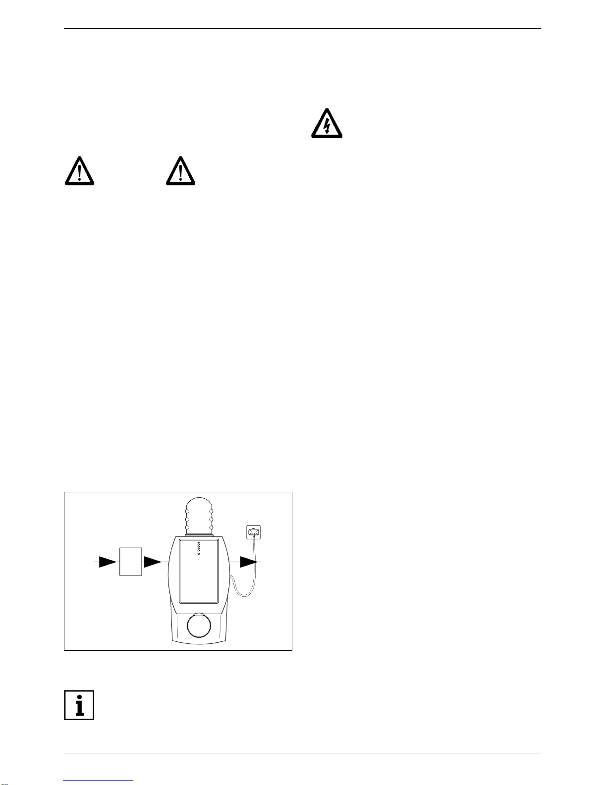
– Direction of flow (see Fig. 1)
– Type plate
– Cleaning information
must always be observed and kept in a fully
legible condition.
ATTENTION Notes on existing
dangers
Warning, electrical voltage
Torques specified by the
manufacturer.
Tips for use and other
information.
Fig. 1: Built-in rotary flange

6 JUDO BIOSTAT-COMBIMAT
About this Operating Instructions
1.2
Safety information and dangers
due to non-compliance
Failure to observe the general danger
symbols may result, for example, in the
following risks:
– Failure of important functions of the
water treatment device.
– Danger to persons due to electrical and
mechanical effects.
– Danger to persons and the environment
due to leaks.
Refrain from any unsafe working methods.
Failure to comply with this instruction
manual and the safety information can not
only result in dangers for people but can
also harm the environment and the unit.
1.3 Units used
In derogation of the International System of
Units (SI = System International), the follo-
wing units are used:
Units Conversion
°F °F = 9/5 °C + 32
psi kPa = 0.001 N/mm²
gpm 1 m³/h = 4.4 gpm
¾" DN 20
1" DN 25
1½" DN 40

JUDO BIOSTAT-COMBIMAT 7
Intended Use
2. Intended Use
Installation and use of the water treatment
devices are each subject to the applicable
national regulations.
Apart from the instruction manual and the
legally binding accident prevention provi-
sions applicable in the country and place of
use, the recognized technical regulations for
safe and proper work must also be
observed.
The water to be treated must possess
quality of drinking water!
Always contact the manufacturer/supplier
before using water with a different quality or
with additives!
This water treatment devices is suitable for
use in cold drinking water up to maximum
ambient temperature of 86 °F (30 °C).
It is produced according to the newest
standards of technology and the generally
accepted safety regulations in Germany.
The water treatment devices may only be
used as described in the instruction manual.
Any other or further use is deemed not to be
intended use.
Additional dangers exist in case of non-
intended use and failure to observe the
danger symbols and safety information. The
manufacturer/supplier are not liable for any
losses or damage resulting from this. The
risk is solely borne by the user.
Intended use also includes observing the
instruction manual.
The manufacturer/supplier must always be
consulted before using the water treatment
devices outside the use limitations given in
the instruction manual.
The water treatment devices are only to be
used in a technically perfect condition, for
their intended use, safely and aware of the
dangers and with full observance of the
instruction manual!
Have any malfunctions corrected imme-
diately!
In order to be able to discharge safely the
wastewater in operation and in case of any
defect in the system, precise compliance
with the details stated in the chapter on
“Requirements for the place of installation”
is necessary!
Use is permitted in the whole field of drinking
water, provided the water to be treated is not
calcium-antagonistic.

8 JUDO BIOSTAT-COMBIMAT
Intended Use
2.1 Water pressure
The water pressure must be between 22 psi
(150 kPa) and 116 psi (800 kPa).
If the water treatment device is not regularily
regenerated, this can result in a pressure
loss and impairment of the softening func-
tion.
ATTENTION
(see chapter “Safety information and
dangers due to non-compliance”)
If the water pressure is more than 116 psi
(800 kPa) a pressure reducer must be
installed before the water treatment device
(see Fig. 2). An operating pressure of more
than 116 psi (800 kPa) can lead to malfunc-
tion and failure.
The optimaloperating pressure for the water
treatment device lies between 44 psi (300
kPa) and 73 psi (500 kPa). It works most
economically under these pressure condi-
tions. In modern sanitary installations (in
particular where single lever mixers are
used), despite normal system pressure
conditions, peak pressures of up to over 440
psi (3000 kPa) frequently occur. This can
cause damage to important functional inte-
rior parts of the water treatment device.
2.2 Notes on special dangers
2.2.1 Electrical equipment /
installations
Electricaldevices / equipment, which are not
splash proof and which are located near the
water treatment device can be damaged by
water which escapes from the water treat-
ment device during “Cleaning - Flushing” or
improper use. If the electrical devices /
installations are connected to the power
supply, a short circuit can also occur. In this
case there is a risk of people suffering an
electric shock. Electrical devices / equip-
ment located near the water treatment
device must therefore be splash proof and
comply with the legal regulations for wet
rooms (IP44).
Fig. 2: Pressure reducer upstream of the water
treatment device.
For a water pressure of 73 psi
(500 kPa) to 116 psi (800 kPa) we
recommend the installation of a
pressure reducer.
1
1 = Pressure reducer
There must not be any electrical
cables and devices underneath or in
the immediate vicinity of the water
treatment device!

JUDO BIOSTAT-COMBIMAT 9
Product Information
3. Product Information
3.1 Intended purpose
This water treatment device is suitable for
use in cold drinking water up to a maximum
water temperature of 86 °F (30 °C).
ATTENTION
(see chapter “Safety information and
dangers due to non-compliance”)
Please refer to the chapter on “Intended
Use” for use restrictions.
This water treatment device reduces the
tendency of the water to precipitate out
excess calcium and thus protects the water-
pipes and water heaters from lime deposits.
Appliances and taps are protected.
3.2 Materials used
Theused materialsare resistant to the phys-
ical, chemical and corrosive properties to be
expected in the drinking water. All materials
are hygienically and physiologically safe.
Plastics (KTW recommendations) and
metallic materials fulfil the requirements of
the BgVV (German Federal Institute for
Consumer Health Protection and Veterinary
Medicine).
4. Installation
4.1 General
ATTENTION
(see chapter “Safety information and
dangers due to non-compliance”)
The unit may only be installed by skilled
personnel.
The chapter on “Intended Use” has always
to be observed !
The pipes must be able to support in a safe
way the water treatment devices.
Otherwise mechanical damage or fractures/
bursts can occur in the pipes. This can result
in major water damage. People close to the
water treatment device are exposed to a
health risk due to the large quantities of
water released. Therefore, if necessary, the
pipes must be additionally fixed or
supported.
Always observe the given spacings to
ensure convenient operation and servicing
(see chapter “Mounting Dimensions”)
A distance of at least 6 Inch (150 mm) above
and below the water treatment device
is required in order to be able to carry out
property all the maintenance and servicing
work.
When installing the water treatment devices
in the feed-pipe to the water heater, ensure
that the safety valve of the water heater is
located after the water treatment device in
the direction of flow.
Lime deposits restrain the water
flow and can therefore lead to an
increased energy consumption.

10 JUDO BIOSTAT-COMBIMAT
Installation
4.2 Requirements for the place of
installation
The room where the unit is installed must
be dry and frost free!
Unauthorised persons must not have
access to the water treatment device!
ATTENTION
(see chapter “Safety information and
dangers due to non-compliance”)
– The ambient temperature must not
exceed 86 °F (30 °C)! At higher
temperatures or direct sun radiation the
material can be damaged.
– We recommend that the water treatment
devices is installed after a backwash
protective filter, to prevent particles of
dirt and sand being swept in.
– Length of the power lead is approxi-
mately 60 Inch (1.5 m).
– Particularly in the case of small cross-
sections and soft pipe materials, the
water pipes should be supported in the
vicinity of the connecting flange with two
pipe-clamps.
4.2.1 Installed position
ATTENTION
(see chapter “Safety information and
dangers due to non-compliance”)
Always install the water treatment devices
in a vertical position (± 5°)!
Unless, impairments of its function can
occur.
4.2.2 Power supply
ATTENTION
(see chapter “Safety information and
dangers due to non-compliance”)
A permanent power supply must be avail-
able. If the water treatment devices is not
permanently supplied with power, there is
no warning in case of faults, and no water is
treated.
4.2.3 Mounting the built-in rotary
flange
The built-in rotary flange is used as a
connecting element between the pipe and
the water treatment device.
It is suitable for both, -horizontally and verti-
cally mounted pipes.
The built-in rotary flange must be
installed in the direction of flow. This is
marked by a cast in arrow (see Fig. 1).
If these instructions aren't respected, the
water treatment device doesn't work.
Apowerconnection(120V, 60 Hz),
which has to be permanently
under voltage, must be available.
A splash proof socket is required
for the power supply, in accord-
ance with the legal regulations for
wet rooms.

JUDO BIOSTAT-COMBIMAT 11
Installation
ATTENTION
(see chapter “Safety information and
dangers due to non-compliance”)
The flange surface of the built-in rotary
flange must be in a vertical position! The
built-in rotary flange must be fitted thus that
mechanical stresses cannot occur! Other-
wise mechanical damages can arise at the
built-in rotary flange. This can lead to major
water damages.
In this case, people close to the water treat-
ment devices are exposed to a health risk
due to the large quantities of water.
Therefore, when mounting, ensure that no
large forces act on the pipe, built-in rotary
flange and water treatment devices.
4.2.4 Mounting of the Bypass Valve
(accessories)
The flange of the bypass valve marked with
the cast in letter “R” (pipe) is screwed onto
the built-in rotary flange. The conditioner is
fitted onto the flange marked with the cast in
letter “G” (unit). The hand-wheel of the
bypass valve can be positioned anywhere
above the unit or to the side if there is
enough space between the pipe and wall.
Depending on conditions on site,installation
should be carried out ensuring sufficient
access to the hand-wheel.
4.2.5 Fitting the wall support
Fig. 3: Bypass valve
Fig. 4:
Wall support without bypass valve
„R“ pipe flange
„G“ unit flange
Built-in rotary flange
Hand-wheel
Wall support
< 12 Inch
(300 mm)

12 JUDO BIOSTAT-COMBIMAT
Installation
For further information, please refer to the
installation instructions for the wall support.
4.2.6
Mounting of the
Water
Treatment Device
After flushing the water pipe, remove the
assembly lid of the built-in rotary flange.
Remove the white protective disc on the
connecting flange of the water treatment
devices by unscrewing the four M6 Allen
screws.
Do not completely unscrew the screws
because of the bayonet connection!
Lift up the water treatment devices and
swivel it approx. 30° in an anti-clockwise
direction. Position it on the built-in rotary
flangeso that the screw heads pass through
the bayonet fixing drill holes (see Fig. 6 I).
Swivel the water treatment devices approx.
30° back ina clockwise direction and tighten
the four hexagon socket screws (see Fig. 6
II).
The profile of the profiled flange gasket must
point towards the built-in rotary flange.
Failure to observe this can lead to leaks and
water escaping. This can cause damage
due to water to the house and its installa-
tions (see Fig. 7).
4.3 Discharging the flushing water
An adequately dimensioned wastewater
connection (e.g. floor drain) according to
DIN 1986 must be available for the flushing
water
.
The dimensioning depends on the local
circumstances (e.g. wastewater pipe
gradient, number of pipe bends, length of
the wastewater pipe, etc.). The dimen-
sioning must at least ensure that all the
wastewater can be discharged temporarily
coordinated.
If it is not possible to locate a drain connec-
tion directly under the water treatment
device
s
, thewastewater hose can be routed
over the water treatment device.
Fig. 5: Wall support with bypass valve
Fig. 6: Built-in rotary flange with bayonet fixture
Wall support
> 12 Inch
(300 mm)
III
Fig. 7: Built-in rotary flange
Select the torque (approx. 4 Nm) so
that the gasket locks and the water
treatment device is not damaged or
strained!
Profiled flange gasket

JUDO BIOSTAT-COMBIMAT 13
Installation
The wastewater hose for the flushing water
must be led to the drainage channel without
any kinks.
In all options, a free discharge must be
ensured in accordance with EN 1717.
The loose end of the hose has to be firmly
fixed with the included adhesive tape at the
pipe or a similar object.
The flushing water must be discharged into
a firmly mounted drain.
Flushing water discharge options
Ensure that the wastewater con-
nection functions before plug-
ging the power supply unit into
the socket.
Fig. 8: Flushing water discharge options
> 1 Inch
(20 mm)
ø 50 mm
> 6 Inch
(150 mm)

14 JUDO BIOSTAT-COMBIMAT
Operation
5. Operation
ATTENTION
(see chapter “Safety information and
dangers due to non-compliance”)
Always observe the chapter on “Intended
Use”!
5.1 Commissioning
For safety reasons, the water treatment
devices must be vented immediately after
having been connected with the water
supply. Set the bypass valve supplied at the
setting "Operation" (see chapter “Mounting
of the Bypass Valve (accessories)”).
– Turn on a water tap mounted after the
water treatment devices.
–
The power supply must be freely acces-
sible
.
– After the power supply has been
connected, the electrical circuit performs
a self-check of all the functions and
parameters stored in the electronics.
– Following a successful check, all control
lamps flashes four times.
– As soon as LED 1 shows a continuous
green light indicating "Operation", the
water treatment devices is ready for use.
When water is flowing, the green LED 1
flashes (see chapter “Control lamps,
manual pushbuttons”).
Electrical circuit
Connect the water treatment device
to the power supply. Plug the power
supply into the socket.
Fig. 9: Electrical circuit
DIP switch
LEDs
Manual
pushbutton
1 5m³
210m³
320m³
440m³
5Ox1
6Ox2
7
8
15 VAC
Batterie
M1
Elektrode
S3
Hall
M2
Alarm

JUDO BIOSTAT-COMBIMAT 15
Operation
5.2 Description of its function
1Control lamps
2Manual pushbutton
3Type Plate
4Panelling
5Cleaning motor
6Flushing motor
5.2.1 Treatment effect
The water treatment device works
completely automatically. The treatment
effect is adapted at the water flow. In the
feed to the water treatment device there is a
flow-meter.
The flow-meter consists of a propeller water
meter.
Due to the water flow the screw propeller,
that can be found in the propeller water
meter rotates, and a Hall Sensor receives
impulses from the magnet in the propeller.
The electronics then calculate the waterflow
from the frequency and quantity of the
impulses. The electronics regulate the treat-
ment current referring to the relation that
exists between the applied voltage and the
treatment current as well as from the dura-
tion of the treatment current [impulse
length). The electronics optimise the treat-
ment current, according to the quality of the
water.
As soon as water flows, the water treatment
is indicated by the flashing of green LED 1
(see fig. 12).
Fig. 10: BST-CA
1
2
3
5
6
4

16 JUDO BIOSTAT-COMBIMAT
Operation
5.2.2 Lime protection function
The water treatment devices sets free the
minute seed crystals to which further lime
can attach itself. In the treatment section,
there is a titanium anode (positive pole) and
a circular stainless steel brush switched as
the cathode (negative pole). As soon as
water flows, there is a pulsating direct
current applied to these two electrodes so
that there is a flow of electricity between the
electrodes. Dissolved calcium in the form of
calcium carbonate crystals is then deposited
on the cathode (the circular stainless steel
brushes). On cleaning, these crystals of
calcium carbonate are thrown off the sepa-
rate bristles by rotating the circular brush.
The crystals thus formed are minute micro-
crystals. Larger crystals which may possibly
also appear sink together with separate
loose brush particles to the bottom and are
flushed out via the flushing valve during
cleaning.
The lime particles can be seen in the
flushing water as very fine "sand". The
microcrystals remain in suspension and
thus form seed crystals onwhich furtherlime
can be deposited. Principally in the warm
water field the growth of the crystals can be
realized by a gradual clouding of the water.
The crystals slowly grow large enough to be
able to disperse the rays of light. At that
stage, they are but a few thousandths of a
millimeter in size. But even these crystals
are small enough to remain in suspension
and to be flushed out with the water flow.
The same process goes on in the cold water
field, too, although the potential here for
deposition of lime is considerably less in
normal circumstances. Since the excess
lime (calcium) is now deposited at the seed
crystals, other surfaces (e.g. pipework,
boiler etc.) are not affected by lime deposits
so that heating elements for example no
longer fur up. Although this formation of
crystals does reduce the hardness of the
water, the reduction is so small that they
remain undetectable by means of simple
measuring instruments.
In the feed of the unit, is a propeller water
meter which can even detect such small
flows of water as 1.5 l/min. Together with a
microprocessor-controlled electronics,
optimal water treatment is ensured at all
times from tiny flows up to the nominal
capacity, and also depending on the water
quality by adapting the electrical impulses.

JUDO BIOSTAT-COMBIMAT 17
Operation
5.2.3 Hygiene unit
In addition to its lime-protection function,the
water treatment devices also fights bacteria
such as that one which causes legionnaires'
disease and herewith their increase. This is
achieved by means of the proven anodic
oxidation method.
The hygiene unit in the water treatment
devices consists of an electrode specially
coated with a mixture of oxides of precious
metals as an additional anode and an elec-
tronic control unit. The approved circular
stainless steel brush is used here, too in the
hygiene unit as adeposition cathode in addi-
tion to its function as a lime protection. The
cathode brush is freed of lime depositis from
timeto time by means of a scraper, so that a
pole reversal of the electrodes is not neces-
sary for the cleaning off. By avoiding regular
pole reversal it is taken care of the elec-
trodes and their service life is prolongated.
As soon as the water flows, by applying a
small voltage out of the water itself, without
the addition of chemicals, oxidants are
produced which attack the legionella bacte-
rium.
The water treatment devices creates a
disadvantageous living environment for the
legionella bacteria, but must not be used,
however in legionnaires' disease-contami-
nated water systems as the sole protection
against legionnaires' disease. In these
circumstances, measures for disinfection
have to be adopted here as further steps, in
accordance with the DVGW working sheet
W551, in order to kill the legionella bacteria
completely.
The use of the water treatment devices does
not replace a disinfection in the usual sense,
but serves as a prophylatic measure to
protect as far as possible against the danger
of an increase of the germs.
5.3 Control lamps,
manual pushbuttons
Fig. 11: Control lamps, manual pushbuttons
LED 1 Operation - Conditioning
Permanent green light: the water treat-
ment device is ready for use.
Green light flashing: water treatment is
taking place.
LED 2 Cleaning - Flushing
Permanent green light: a flushing - flush-
ing is being carried out.
LED 4 Battery low
Red light flashing: the battery must be
changed otherwise no further Cleaning -
Flushing can be carried out.
LED 5 Fault
Red flashing light: the water treatment
device is not ready for use (see chapter
“Fault”).
Hand manual pushbutton
Triggers Cleaning - Flushing.
LED 1
LED 2
LED 4
LED 5
Hand
Operation - Conditioning
Cleaning - Flushing
Fault
Manual Cleaning - Flushing
Battery low

18 JUDO BIOSTAT-COMBIMAT
Operation
5.4 Cleaning - Flushing
Depending on the quality of the water and
the operating methods, a thin coating of lime
is formed on the brush in the treatment
chamber. This lime layer must be removed
and flushed out of the water treatment
devices at regular intervals.
The water treatment device has a device for
flushing the brush and a flush valve for
rinsing out the lime particles.
Cleaning and flushing is carried out auto-
matically by two electric motors.
During Cleaning - Flushing, the yellow LED
2 lights up.
The Cleaning - Flushing can be started
manually by operating the manual push-
button (2).
5.5 Warning message "Battery
low"
To ensure thatCleaning -Flushing is carried
out completely, even in case of a power
failure, the water treatment appliance has a
9V block battery installed as an emergency
power supply.
Before each Cleaning - Flushing a battery
test will be effected. A missing, unloaded or
defective battery is indicated by the flashing
of the red LED 4. A trigging of the container
flushing is then not possible.
5.6 Mounting of the panelling
Dismantling:
– Withdraw the upper / inferior clamping
fixture.
– Carefully pull apart the right and the left
panel parts by the handle cavities on
the back of the panelling.
– Remove the type plate and the panel-
ling.
Assembly:
– Push the right and left parts of the panel-
ling together till a gap of approximately
15 mm is left.
– Ensure that the cable is not trapped!
– Refit the type plate in the blanks, of the
panelling, situated above and below.
– Push the panelling completely together.
5.7 Replacing the batteries
When a change of batteries is necessary
(LED 4 flashes) the following procedure is
adopted:
Make sure that the drain connec-
tion is functional before plug-
ging the power supply into
the socket (see chapter “Dis-
charging the flushing water”). Disconnect the power supply
from the socket.
Plug the power supply into
the socket!

JUDO BIOSTAT-COMBIMAT 19
Operation
– Remove the panelling from the water
treatment devices.
– The battery is located behind the elec-
trical switch and must be disconnected
from the battery clip.
– Exchange the battery and push it back
into the corresponding blank behind the
switch.
– Remount the panelling on the water
treatment devices.
– Return run-down batteries to a distri-
butor or to a properly- authorised local
disposal return point.
5.8 Modifications / changes /
spare parts
ATTENTION
(see chapter “Safety information and
dangers due to non-compliance”)
Only original spare parts are to be used!
Independent modifications and changes are
prohibited for safety reasons! These can
impair the function of the water treatment
device, lead to lead and in extreme cases
can cause the water treatment device to
burst.
The test marks imprinted on the unit are only
valid if original spare parts are used.
Disconnect the power supply
from the socket.
Plug the power supply into the
socket!
Only use 9 V alkaline type block
batteries - see battery descrip-
tion.

20 JUDO BIOSTAT-COMBIMAT
Operation
5.9 Stoppages
ATTENTION
(see chapter “Safety information and
dangers due to non-compliance”)
If a water treatment device has to be
removed from the flange or unscrewed, the
chapter on “Intended Use” must always be
observed!
– Protect the flange surfaces from
damage! Damaged flanged surfaces
cannot close tight. As a result, escaping
water can damage the building and
installations.
– Ensure that no dirt can get into the water
treatment device! This dirt can get into
contact with and be discharged into the
drinking water when the water treatment
device is switched back on. The health
of people who drink dirty water is at risk.
– Store the water treatment device in frost-
free conditions! Frost can cause any
water contained in the water treatment
device voids to freeze and thus cause
mechanical damage to the water treat-
ment device so that it leaks at operating
pressure or canburst.Leaking water can
cause major damage to the building. In
addition, people near the water treat-
ment device can be injured by breaking
off water treatment device parts.
– When restarting the water treatment
device, follow the instructions for a new
water treatment device.
This manual suits for next models
1
Table of contents
Other Judo Water System manuals
Popular Water System manuals by other brands

Mikrofill
Mikrofill Extreme Series Technical documentation

Orbit
Orbit 27752 user manual

Vollrath
Vollrath Sous Vide 60038 Operator's manual

Clear Comfort
Clear Comfort CCW300A Installation, operation & maintenance manual

PAW
PAW HeatBloC K32 DN 25 Installation & operation instructions

Atlas Filtri
Atlas Filtri DOSAPLUS 2 quick start guide