CONTENTS
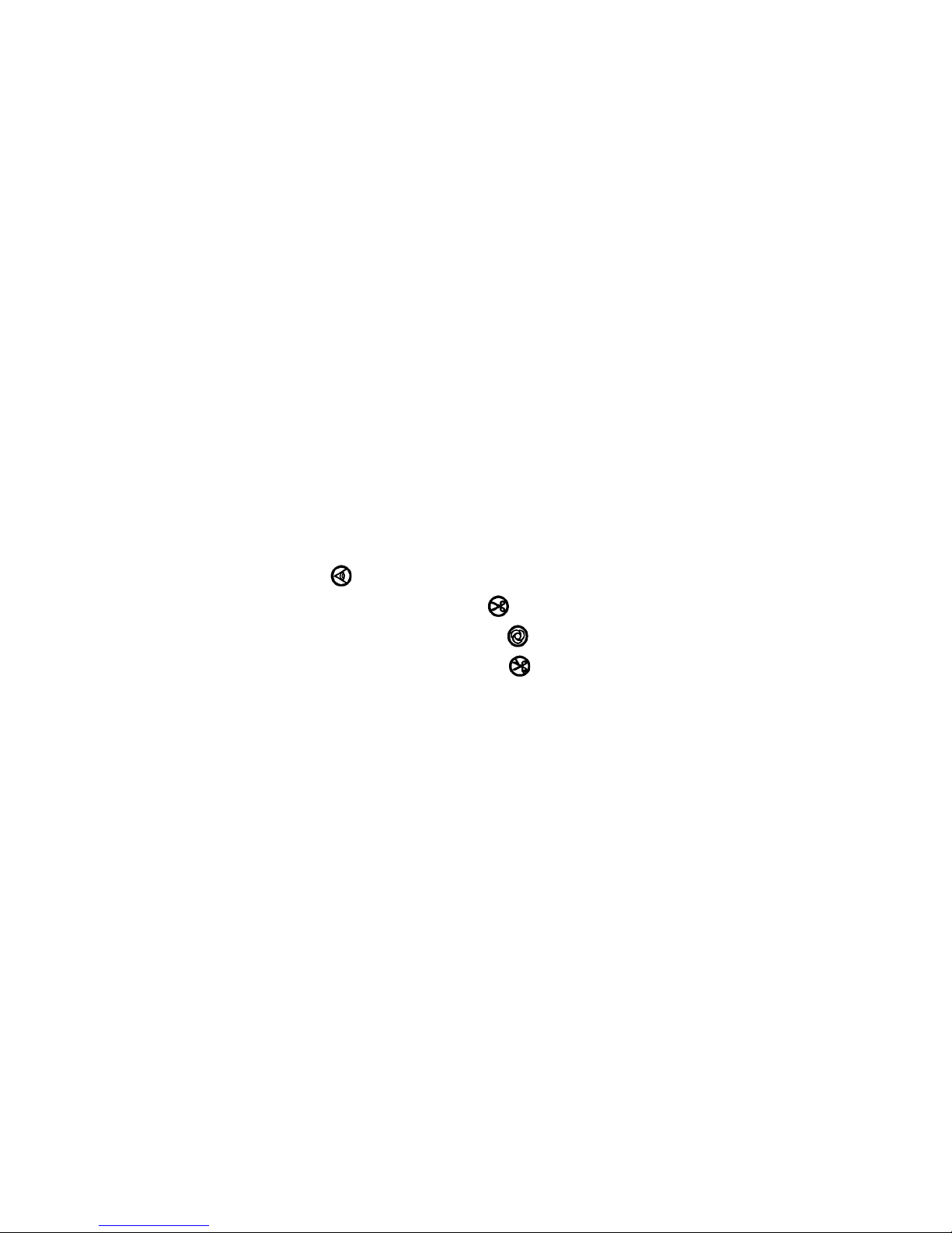
1. INSTALLING THE OPERATION PANEL................................................................... 1
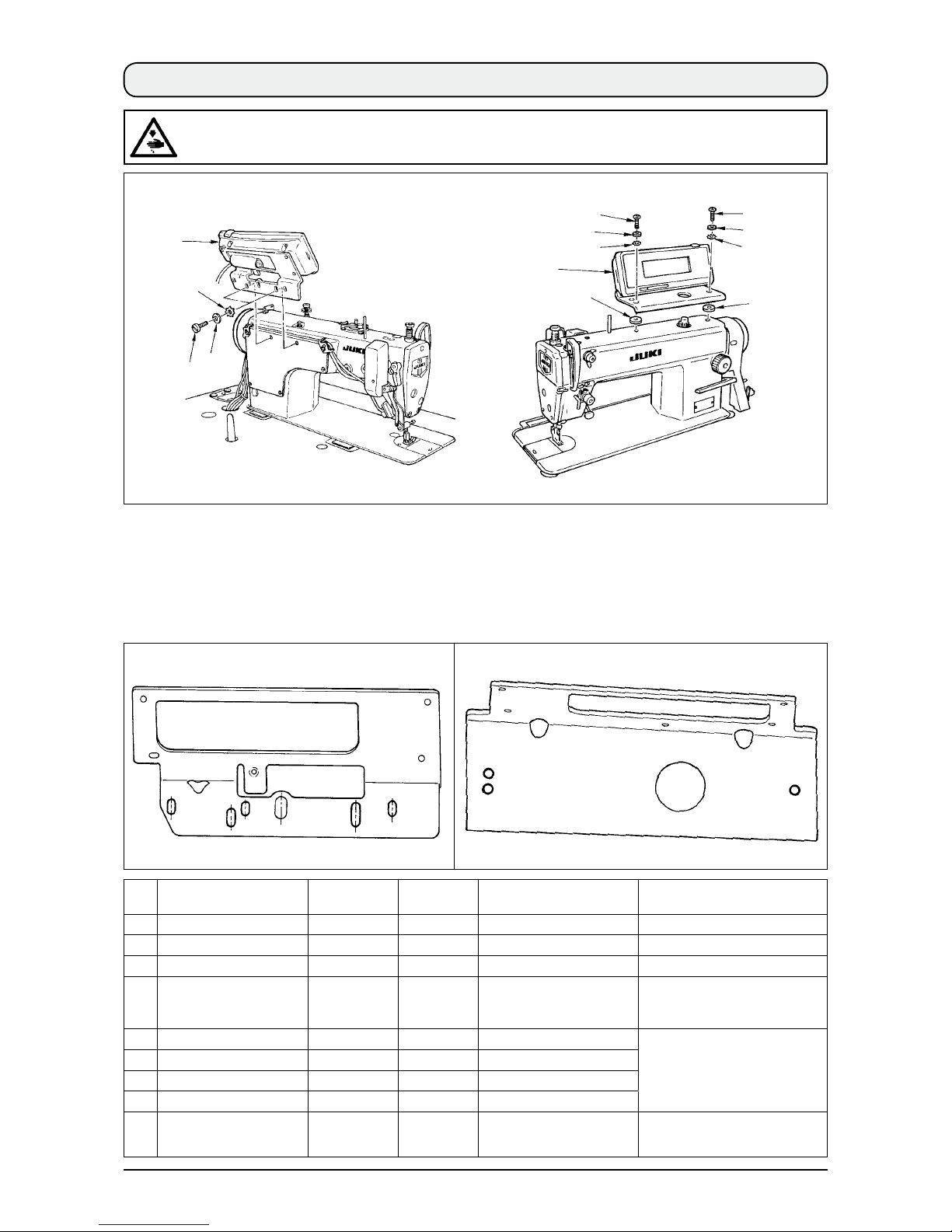
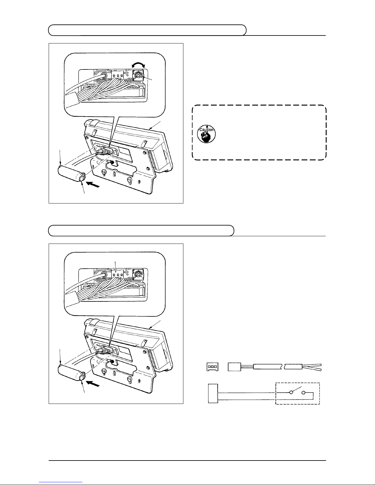
2. CONNECTING THE CORD........................................................................................ 2
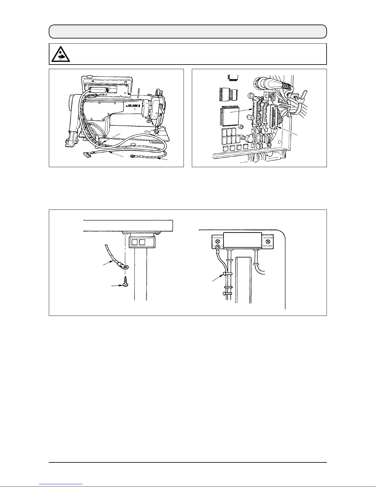
3. HOW TO USE THE OPERATION PANEL ................................................................. 3
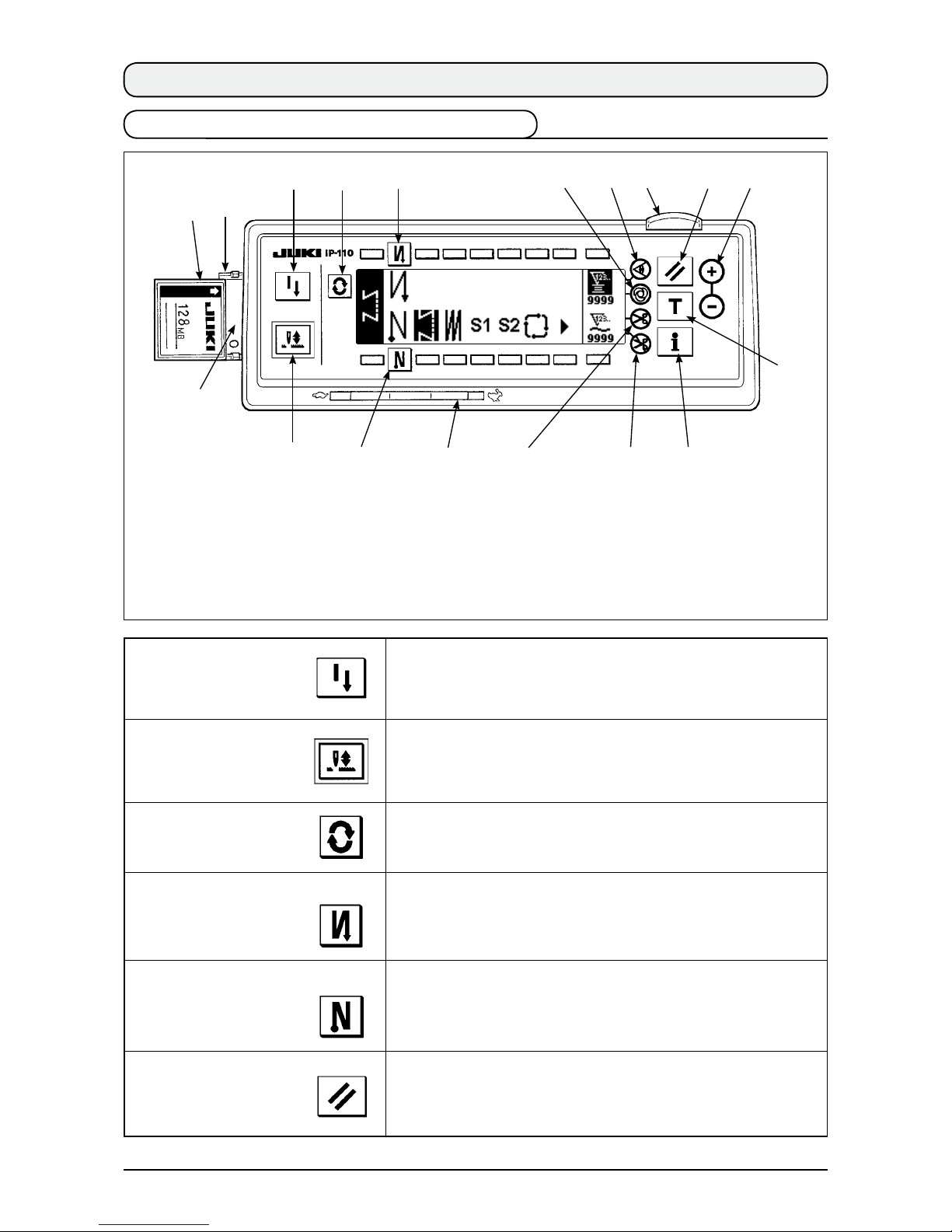
3-1. Names and functions of each components .....................................................3
3-2. Adjusting the contrast of the operation panel display....................................5
3-3. Production control switch connecting connector...........................................5
4. STANDARD PANEL................................................................................................... 6
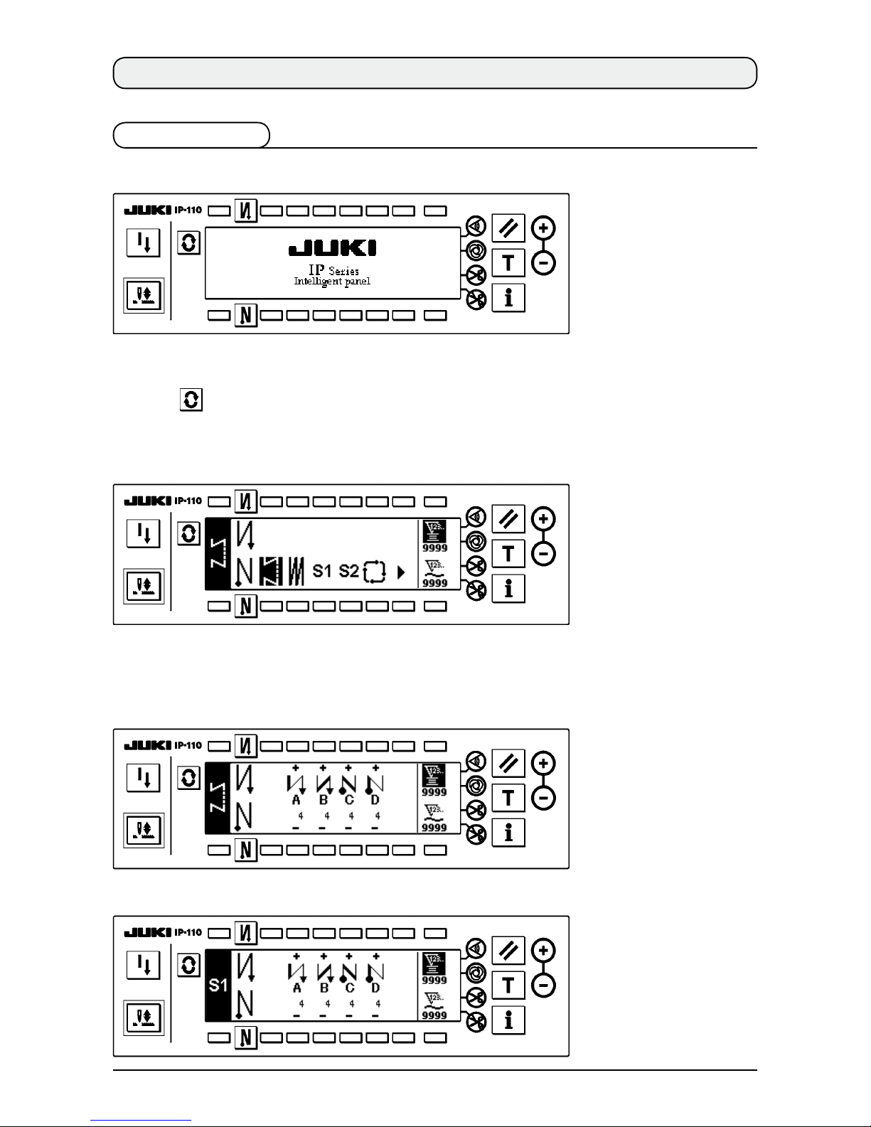
4-1. Basic screen........................................................................................................6
4-2. How to operate the operation panel for sewing stitching patterns ...............8
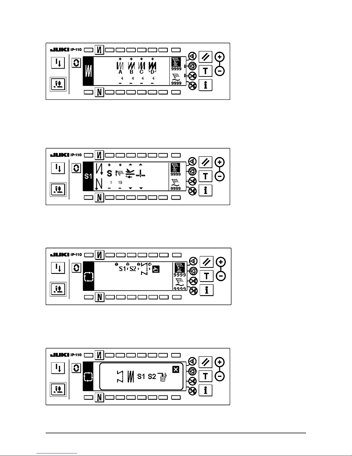
(1) Reverse stitching pattern...................................................................................................................8
(2) Overlapped stitching pattern ...........................................................................................................10
(3) Programmed stitching pattern......................................................................................................... 11
(4) Cycle sewing pattern ........................................................................................................................15
4-3. How to use the bobbin thread counter ...........................................................17
4-4. No. of pcs. counter ...........................................................................................18
4-5. Re-sewing switch..............................................................................................18
4-6. Needle up/down compensation switch...........................................................19
4-7. ON/OFF switch of the material edge sensor.............................................19
4-8. Automatic thread trimming switch ............................................................19
4-9. One-shot automatic stitching switch ........................................................19
4-10. Thread trimming prohibition switch ........................................................20
4-11. Key lock ...........................................................................................................20
4-12. Information ......................................................................................................21
(1) Maintenance management function................................................................................................21
(2) Production control function.............................................................................................................25
(3) Working measurement function ......................................................................................................27
4-13. Setting for functions.......................................................................................29
(1) How to change over to the function setting mode ........................................................................29
(2) Function setting list..........................................................................................................................32
5. PANEL FOR LH-4168/4188 ..................................................................................... 37
5-1. Basic screen......................................................................................................37
5-2. How to operate the operation panel for sewing stitching patterns .............41
(1) Reverse stitching pattern.................................................................................................................41
(2) Overlapped stitching pattern ...........................................................................................................43
(3) Corner pattern ...................................................................................................................................44
(4) Step pattern .......................................................................................................................................50
(5) Cycle sewing pattern ........................................................................................................................53
5-3. How to use the bobbin thread counter ...........................................................54
5-4. No. of pcs. counter ...........................................................................................55
5-5. Re-sewing switch..............................................................................................56
5-6. Needle up/down compensation switch...........................................................57