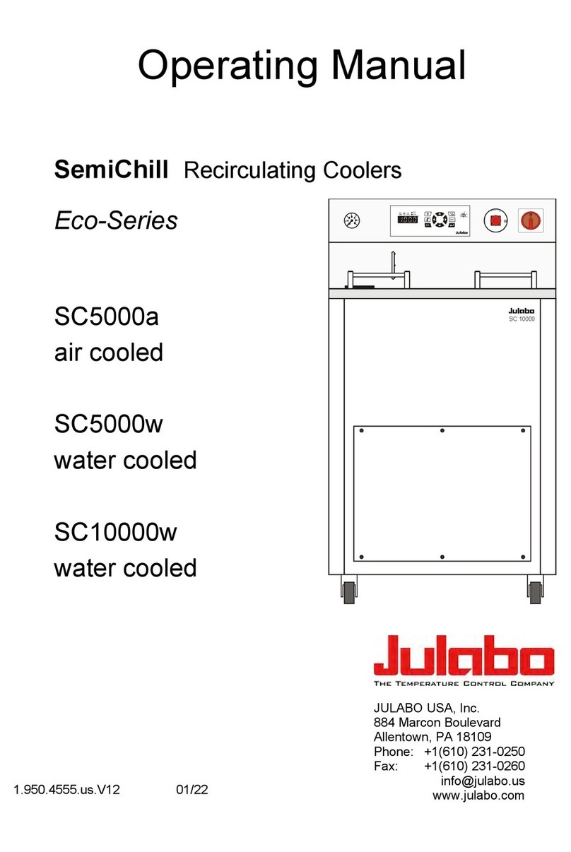
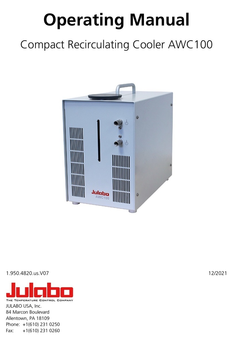
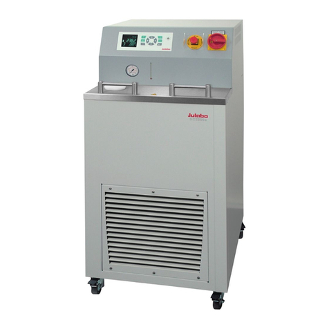
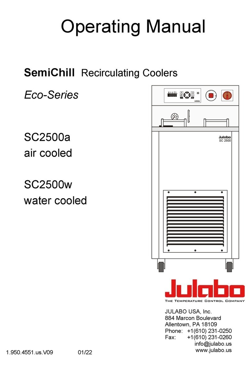
Julabo AWC100 Installation instructions

Compact Recirculating Cooler
Original operating manual
1.950.4820.en.V08 06/2022

2
Legal
JULABO GmbH
Gerhard-Juchheim-Strasse 1
77960 Seelbach / Germany
Tel.: +49 7823 51-0
Fax: +49 7823 2491
Info.de@julabo.com
www.julabo.com
The content of this operating manual is protected by copyright. Information,
including texts, images, and other contents may not be reproduced, distributed,
transmitted, stored or otherwise used in any form without prior explicit written
consent.
Illustrations in this operating manual are for illustrative purposes and are not
necessarily displayed to scale.

3
Contents
1Foreword............................................................................................ 4
2About this manual............................................................................. 5
2.1 Original JULABO spare parts......................................................... 5
2.2 Accessories.................................................................................... 5
2.3 Warnings........................................................................................ 5
2.4 Symbols used................................................................................. 6
3Intended use ...................................................................................... 7
4Safety ................................................................................................. 8
4.1 General Safety Instructions for the operating company.................. 8
4.2 General Safety Instructions for the operator................................... 8
4.3 General safety instructions for bath fluids ...................................... 9
4.4 Safety symbols............................................................................. 10
5Product description ........................................................................ 10
5.1 Function description ..................................................................... 10
5.2 Operating and functional elements............................................... 11
5.3 Technical data.............................................................................. 12
5.4 Bath fluids .................................................................................... 13
6Transport and installation .............................................................. 14
7Initial operation................................................................................ 15
8Operation ......................................................................................... 16
9Maintenance..................................................................................... 17
9.1 Replace detachable power cord................................................... 17
9.2 Emptying ...................................................................................... 17
9.3 Clean device ................................................................................ 18
9.4 Device storage ............................................................................. 19
9.5 Technical Service......................................................................... 19
9.6 Warranty....................................................................................... 20
9.7 Device disposal ............................................................................ 20
10 EC Declaration of Conformity ........................................................ 21
11 UK Declaration of Conformity ........................................................ 22

Foreword
4
1 Foreword
Congratulations!
You have made an excellent choice.
JULABO would like to thank you for the trust you have placed in our company
and products.
This operating manual will help you become acquainted with the use of our
units. Read the operating manual carefully. Keep the operating manual handy at
all times.
If you have any questions regarding the operation of the unit or the operating
manuals, please call us or send us an e-mail or fax.
Contact:
JULABO GmbH
Gerhard-Juchheim-Strasse 1
77960 Seelbach/Germany
Tel. +49 782351-0
Fax +49 7823249
info@julabo.com
www.julabo.com

About this manual
5
2 About this manual
This manual is intended for the equipment specified on the cover page.
NOTE
Observe the safety instructions!
Read the Safety section of this manual before using the equipment for the
first time.
2.1 Original JULABO spare parts
Hassle-free continuous operation and safety also depend on the quality of the
spare parts used.
Only original JULABO spare parts guarantee the highest possible quality and
safety. Original JULABO spare parts are available directly from JULABO or your
specialist dealer.
Please note that JULABO cannot provide a warranty service if non-original
JULABO spare parts are used.
2.2 Accessories
JULABO offers a wide range of accessories for the devices. Accessories are not
described in this manual.
The complete range of accessories for the devices described in this manual can
be found on our website www.julabo.com. Use the Search function on the
website.
2.3 Warnings
The manual contains warnings to increase safety when using the device.
Warnings must always be observed.
A warning sign displayed in signal color precedes the signal word. The signal
word, highlighted in color, specifies the severity of the hazard.

About this manual
6
CAUTION
This signal word designates a danger with a low level of risk which, if it not
prevented, may result in minor to moderate injuries.
WARNING
This signal word designates a danger with a medium level of risk which, if it
not prevented, may result in death or serious injuries.
DANGER
This signal word designates a danger with a high level of risk which, if it not
prevented, will result in death or serious injuries.
NOTE
This signal word designates a possibly harmful situation. If it is not avoided,
the system or objects in its vicinity may be damaged.
2.4 Symbols used
Various symbols are used throughout this manual to aid reading
comprehension. This list describes the symbols used.
Tools needed for the following approach
Prerequisite to be met for the following procedure
1. Numbered action steps
Interim result for individual action steps
Additional note for individual action steps
Final result of a procedure
Thesy mbolshowsthefinalresultof an approach

Intended use
7
3 Intended use
This section defines the purpose of the unit so that the operator can operate the
unit safely and avoid misuse.
Recirculating coolers are intended for the temperature control of liquid media.
An external cooling circuit is connected to the connections, via which media can
be constantly cooled.
Only use the device if it is in technically perfect condition and only use it in
accordance with its intended use. Be aware of safety issues or hazards and
comply with the operating manual! In particular, always immediately rectify
malfunctions that could impair safety!
The recirculating coolers are not suitable for direct temperature control
application of food, other consumables or pharmaceutical or other medical
products.
The devices are not suitable for use in an explosive environment.
Any other uses not listed here are not considered as intended.

Safety
8
4 Safety
4.1 General Safety Instructions for the operating company
This section outlines the General Safety Instructions that must be observed by
the operator to ensure safe operation.
• The operator is responsible for the qualifications of its operating personnel.
• The operator must ensure that the operating personnel has been instructed
in use of the device.
• The device operators must receive regular training about the dangers
involved in their work and measures to prevent such dangers.
• The operator must ensure that persons entrusted with the operation,
installation and maintenance have read and understood the operating
manual.
• The device may only be configured, installed, maintained and repaired by
trained personnel with appropriate qualifications.
• If hazardous substances or substances that may become hazardous are
used, the device may only be used by personnel who are qualified to handle
these substances and the device.
• The operator must ensure that the device is checked for safety and
functionality at regular and usage-related intervals.
• The operator must ensure that the mains supply has a low impedance to
prevent influencing other devices powered by the same supply.
4.2 General Safety Instructions for the operator
This section outlines the General Safety Instructions that must be observed by
the user to ensure safe operation.
• The unit may be connected to protected earth (PE) mains power outlets only
• The mains plug serves as a safe protective separation from the power
supply network and must always be freely accessible
• Do not attempt to use the unit if the mains cable is damaged
• Install the unit on an even surface on a supporting layer made of non-
combustible material
• Be sure to read the operating manual before initial operation
• Use tubing suitable for temperature control purposes
• Secure hose connections against slipping
• Avoid kinking the tubing
• Regularly check tubing for material fatigue, such as cracks
• Never put a damaged or leaking unit into operation
• Before performing service or repair tasks or transporting the unit, switch the
unit off and remove the power plug from the socket
Safety
9
• Completely drain the unit before transporting it
• Switch off the unit and disconnect the mains plug before carrying out any
cleaning work
• Transport the unit carefully
• Shaking or falls may damage the inside of the unit
• Observe safety labels
• Do not remove safety labels
• Service and repairs may be performed by authorised expert personnel only
A
4.3 General safety instructions for bath fluids
Bath fluids must meet a variety of requirements. The following safety
instructions must be observed to guarantee safe operation in the long term.
Please note when using bath fluids:
• Due to its high lime content, hard water is not suitable as a bath fluid as it
can lead to premature calcification of the unit
• Water containing iron can lead to the formation of rust, even on stainless
steel components
• Chlorinated water can lead to pitting corrosion
• Distilled and deionised water can also lead to corrosion of stainless steel
components

Product description
10
4.4 Safety symbols
There are safety symbols included with the device, which should be attached to
the device before initial operation.
Safety
symbols
Description
Warning of a danger zone. Note operating manual
Read operating manual before switching on
Productdescription
5 Product description
5.1 Function description
The recirculating cooler AWC 100 can be used as a cooling unit for water in
closed circuits.
A pump delivers the cooling water via the cooling water outlet into the external
circuit and cools the connected application. The cooling water flows back into
the recirculating cooler via the cooling water inlet. Heat is permanently
extracted from the flowing liquid in the recirculating cooler. The water
temperature depends on the ambient temperature and must not exceed 40 °C.

Product description
11
5.2 Operating and functional elements
The following figure shows the operating and functional elements and their
position on the unit.
Fig. 1: Control and function elements
1
Handle
2
Cooling water reservoir cover
3
Cooling water inlet hose connection
4
Cooling capacity switch
5
Cooling water outlet hose connection
6
Cooling water reservoir min./max. level indicator
7
Mains switch
8
Fuse 2 x T 1,25 A
9
Mains connection

Product description
12
5.3 Technical data
The table contains the technical data of the unit. It refers to the rated voltage
and rated frequency as well as to an ambient temperature of 20°C.
In accordance with IEC 61010-1, the device is designed for safe operation under
the following ambient conditions:
• Indoor use
• Altitude up to 2000 m above sea level
• Ambient temperature +5 … +35 °C
• Maximum relative humidity 80% for temperatures up to 31 °C, decreasing
linearly down to 50% relative humidity at 35 °C
• Mains voltage fluctuations up to ±10 % of the nominal voltage permissible
if not otherwise specified
Protection class according to EN 60 529:
• Protection class IP21
Technical data
Working temperature range °C +20 … +40
Cooling capacity depends on the temperature
difference between the runback and ambient
temperature
°C 20 15 10 5
Stage 0 W 400 320 220 120
Stage 1 W 550 440 300 180
Circulating pump
Flow rate, max.
Pressure, max.
l/min
bar
3.5
0.49
Noise level at 1 m distance db (A) 55
Storage tank filling volume l 0.9
Dimensions (WxHxD) cm 20x34x30
Protection class according to IEC 60529 IP 21
Permissible ambient temperature range °C 5 … 40
Weight kg 11
Mains connection V/Hz 100 … 230/50/60
Current consumption (230 V) A 1
Power cable 3x1 mm², 2.5 m V/A 250/10

Product description
13
5.4 Bath fluids
The most important criterion when selecting the bath fluid is the working
temperature range in which the application is operated.
• Selection of the bath fluid must ensure that the flash point is never
exceeded when it comes into contact with the ambient air.
• Recommended bath fluids and further information can be found on our
website
NOTE
No liability accepted for usage of bath fluids that are not
suitable!
Unsuitable bath fluids that are not approved by JULABO can damage the
water bath.
• Use bath fluids that are recommended by JULABO
• Before filling, check the parts that are in contact with the medium for
compatibility with the bath fluid
• Do not exceed the maximum permissible viscosity during operation
• Consult JULABO before using a bath fluid other than the recommended
one
The unit is suitable for the following bath fluids:
• Softened/decalcified water, temperature range +5 … +80 °C

Transport and installation
14
6 Transport and installation
This section describes how to transport the unit safely.
CAUTION
Risk of injury, device may tip over!
Unsecured devices may tip over during transport and cause injuries.
• Secure the device against tipping and falling during transport
• Secure loose parts against falling during transport
• Transport the device upright and with suitable means of transport
• Wear protective shoes
The unit is switched off and drained.
A suitable transport trolley is ready.
1. Disconnect the mains plug of the unit.
2. Close the cooling water reservoir using the cover.
3. Place the unit upright and centrally on the transport trolley.
4. Secure the unit on the transport trolley against tipping over.
5. Place loose parts, such as cables, with the unit on the transport trolley.
The unit is ready for transport.

Initial operation
15
7 Initial operation
This section describes how to put the unit into operation.
NOTE
Secure the hose connections to prevent them sliding off.
Improper assembly of the hose connections may cause them to leak or slip off
the connection nozzles.
• Secure the hose connections to prevent them sliding off
• After initial operation, check all hose connections for leaks and a secure
fit
NOTE
Do not exceed the maximum filling level in the cooling water
reservoir!
The maximum fill level in the cooling water reservoir must not be exceeded.
When the unit is switched off, excess water can flow back from the external
application and overflow.
• When switching off the unit, prevent the water from flowing back from
the external application
• Insert a stopcock or hose clamp into the external circuit
The unit is unpacked.
1. Place the unit on a horizontal and firm surface.
For good ventilation and heat emission, a distance of at least 20 cm from
the wall and adjacent equipment must be maintained.
2. Connect the unit with the mains plug to a mains power outlet.
3. Connect the hoses of the external application to be cooled to the
connections of the unit.
4. Remove the cover of the cooling water reservoir.
5. Fill the cooling water reservoir with water up to the maximum mark.
6. Close the cooling water reservoir using the cover.
7. Switch unit on at the mains switch.
The pump starts to pump the water through the condenser and the external
application.
8. Observe the level in the cooling water reservoir and top up with water when
the level reaches the minimum mark.
The level should always be between the minimum and maximum marks
during operation.
The unit is ready for operation.
B

Operation
16
8 Operation
The recirculating cooler is very user-friendly. If it is connected to an external
application, it is sufficient to switch it on. No settings are required. The
recirculating cooler is designed for continuous operation under normal
conditions.
The device is ready for use and connected to an external application.
The cooling output switch is set to Stage 0.
1. Switch the device on at the mains switch.
The pump starts to pump the water through the condenser and the external
application. The lower ventilator is active.
2. If you need a higher cooling capacity, switch the cooling capacity to
Stage 1.
The second ventilator is switched on.
The device is in operation.
i

Maintenance
17
9 Maintenance
9.1 Replace detachable power cord
The device is equipped with a detachable power cord.
If the power cord needs to be replaced, ensure that the new one is at least
dimensioned for the device power requirements. Insufficiently dimensioned
power cords must not be used. See type plate for mains voltage and current
value.
We recommend only using original JULABO spare parts.
9.2 Emptying
The device must be completely drained if it is to be sent in for technical service
or is to be properly disposed of.
In general, the device should be completely emptied before longer shutdowns or
when there is a change to the external application.
The unit is switched off.
The external application is disconnected from the unit.
1. Disconnect the mains plug of the unit.
2. Remove the cover of the cooling water reservoir.
3. Provide a sufficiently large collecting vessel.
4. Tilt the unit quickly forwards over the collecting vessel.
The water flows from the cooling water reservoir into the collection vessel
provided.
5. When the cooling water reservoir is completely empty, close it with the
cover.
The unit is emptied.

Maintenance
18
9.3 Clean device
The recirculating cooler is maintenance-free. If the cooling capacity decreases, it
is sufficient to clean it. Proceed as described below.
NOTE
Property damage due to service and repair work not carried out
by an expert!
Service and repair work carried out by unauthorised persons may result in
damage to the unit.
• Service and repair work may only be performed by qualified electricians
• JULABO accepts no liability for property damage caused by service and
repair work not carried out by authorised specialist personnel
Torx screwdriver, size T20
The unit is switched off.
1. Disconnect the external application from the unit.
2. Empty the unit.
3. Remove four fastening screws each on the left and right side of the unit
[arrows, left figure].
4. Carefully remove the hood upwards and disconnect the earthing cable
[arrow, right figure].
5. Use a vacuum cleaner to carefully remove dust and dirt from the inside of
the unit.
6. Position the hood and connect the earthing cable [arrow, right figure].
7. Mount the hood with the fastening screws.
8. Clean the unit surface with a lint-free cloth and a mild cleaning agent.
9. Vacuum the vents.
The unit is cleaned.

Maintenance
19
9.4 Device storage
This section describes how to store the device.
The device is switched off and disconnected from the mains voltage.
1. Empty all system components completely.
2. Clean the device.
3. Carefully dry the device and all its system components, e.g. with
compressed air.
4. Close all connections.
5. Store the device in a dust-free, dry and frost-free location.
The device is protected and can be safely stored there. It can be put into
operation again as needed.
9.5 Technical Service
If the unit shows faults you cannot resolve, please contact our Technical Service.
JULABO GmbH
Technical Service
Gerhard-Juchheim-Strasse 1
77960 Seelbach / Germany
Tel.: +49 7823 51-66
Fax: +49 7823 51-99
Before sending a device to Technical Service, the following points must be
observed:
• Clean and decontaminate the device properly to avoid endangering service
personnel.
• Include a brief description of the fault.
• Package the device safely for shipment.

Maintenance
20
9.6 Warranty
JULABO provides a warranty that the device will function perfectly as long as it
is connected and used correctly and as described in the operating manual.
The warranty period is one year from the invoice date.
With the 1PLUS warranty, the warranty can be extended to two years free of
charge.
The 1PLUS warranty gives the user a free extended warranty to 24 months, limit
to a maximum of 10,000 hours of service.
A prerequisite for this is that the user registers the device at
www.julabo.com, quoting its serial number, within four weeks of initial
operation. The warranty applies from the date of JULABO GmbH’s original
invoice.
9.7 Device disposal
When disposing of the device, the applicable country-specific guidelines must be
observed.
1. Empty the unit completely.
2. Contact an authorised disposal company for disposal of the unit.
It is not permissible to dispose of the unit in household waste or similar
facilities intended for collecting household waste.
The unit can be disposed of properly.
Other manuals for AWC100
4
Table of contents
Other Julabo Accessories manuals

Julabo
Julabo FL1201 User manual

Julabo
Julabo SC 2500w User manual

Julabo
Julabo F250 User manual

Julabo
Julabo SemiChill Eco Series User manual

Julabo
Julabo 950002503P3H0 User manual

Julabo
Julabo Professional Series User manual

Julabo
Julabo SemiChill Eco Series User manual

Julabo
Julabo FT200 User manual

Julabo
Julabo FT200 User manual

Julabo
Julabo AWC100 User manual

Julabo
Julabo Eco Series User manual

Julabo
Julabo FL1201 User manual

Julabo
Julabo FL1201 User manual

Julabo
Julabo FP52-SL User manual

Julabo
Julabo AWC100 User manual

Julabo
Julabo FT402 User manual

Julabo
Julabo SC 5000a User manual

Julabo
Julabo SC 2500a User manual

Julabo
Julabo FT402 User manual

Julabo
Julabo FT200 User manual