JUMPtec superMOPSpro User manual

superMOPSpro Copyright JUMPtec Industrielle Computertechnik AG Page: 1of 93
superMOPSpro
Technical Manual
Rev. 2.2
JUMPtec
Industrielle Computertechnik AG
Brunnwiesenstraße 16
94469 Deggendorf/ Germany
PN of Manual: 96035-0003-00-0
Manual Rev.: 2.2
File: P487m222.DOC

Table of Contents
superMOPSpro Copyright JUMPtec Industrielle Computertechnik AG Page: 2of 93
Table of Contents
Table of Contents ............................................................................................................................2
User Information..............................................................................................................................4
Trademarks ...........................................................................................................................4
General .................................................................................................................................4
Warranty................................................................................................................................5
Introduction......................................................................................................................................6
superMOPSpro......................................................................................................................6
Features................................................................................................................................6
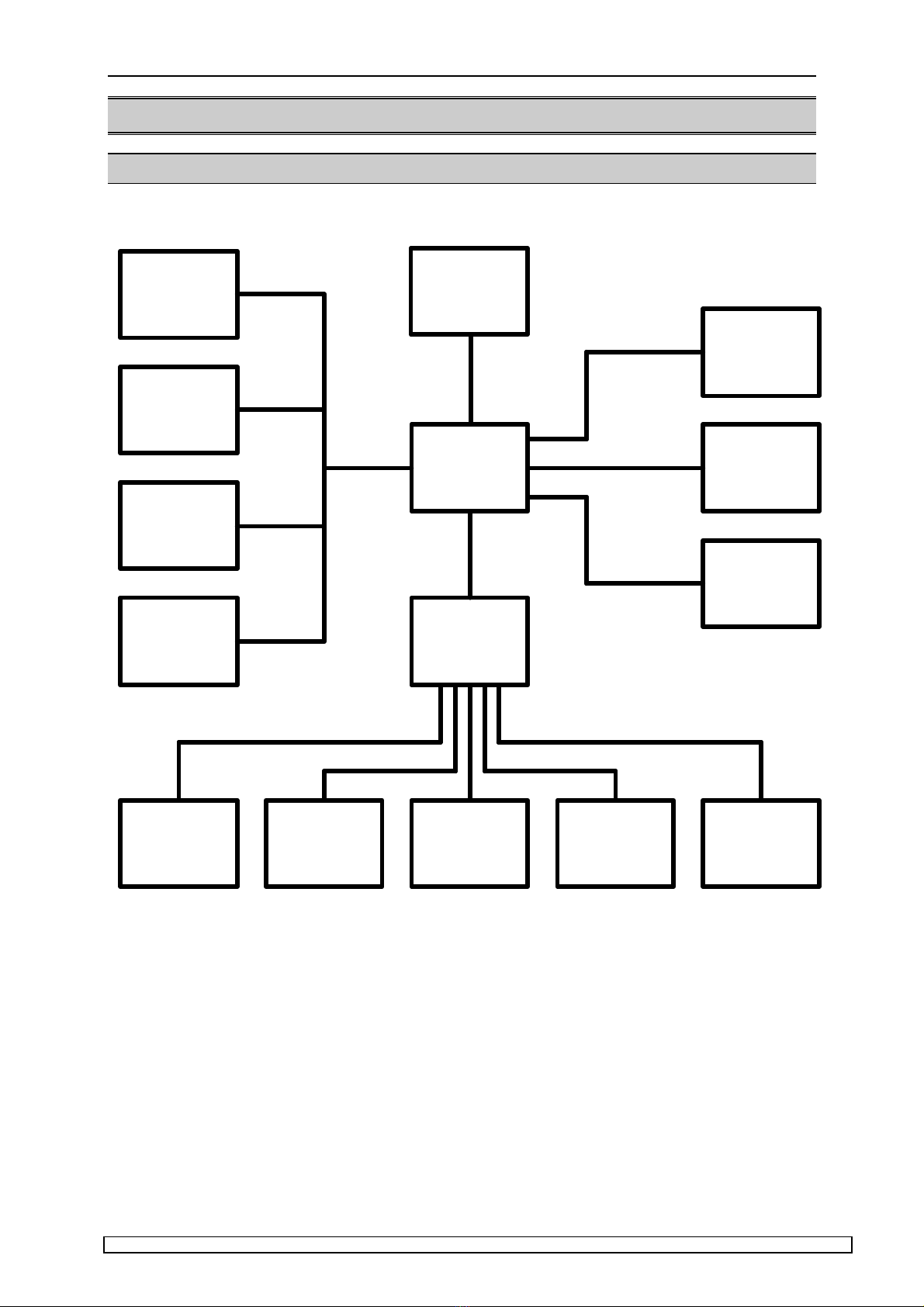
Connector Overview........................................................................................................................9
Block Diagram.......................................................................................................................9
Connector Arrangement.........................................................................................................10
Connector Tables ..................................................................................................................11
Memory and I/O Information............................................................................................................12
Memory Map .........................................................................................................................12
I/O Map .................................................................................................................................15
Interrupts...............................................................................................................................16
DMA......................................................................................................................................16
Working with the superMOPSpro ...................................................................................................17
Introduction............................................................................................................................17
Description of the RTC - CMOS-Setup Menu.........................................................................18
Description of superMOPSpro Extended Setup......................................................................24
Up-/Downgrading a SDisk DIMM Module...............................................................................27
Restrictions of SDisk Usage...................................................................................................27
Watchdog User Interface.......................................................................................................28
Peripheral Interfaces........................................................................................................................29
DC Power Connector (X3)......................................................................................................29
Keyboard, Reset, Battery, Speaker (X9).................................................................................29
Parallel Port (X6)...................................................................................................................31
Serial Ports (X7,X8)...............................................................................................................32
Floppy Connector (X4)...........................................................................................................35
IDE Connector for 2,5" Hard Disk (X10).................................................................................35
Feature Connector (X5) .........................................................................................................36
Ethernet Connector (X11) ......................................................................................................37
RS485 Option........................................................................................................................37
IRDA interface.......................................................................................................................38
I2C-Bus..................................................................................................................................38
The JIDA (JUMPtec Intelligent Device Architecture) Standard......................................................40
Network Operation...........................................................................................................................46
Overview...............................................................................................................................46
Installation.............................................................................................................................48
Diagnostics Overview............................................................................................................68
Technical Support..................................................................................................................72
Setup Utility...........................................................................................................................74
Specifications ..................................................................................................................................76
Mechanical Specifications......................................................................................................76
Physical Dimensions..............................................................................................................76
Electrical Specifications.........................................................................................................77
Environmental Specifications.................................................................................................77
PC/104-Bus Specification of superMOPS..............................................................................78
Signal Description ...........................................................................................................................81
PC/104 Overview ..................................................................................................................81
Address / Data Signal Group..................................................................................................81

Table of Contents
superMOPSpro Copyright JUMPtec Industrielle Computertechnik AG Page: 3of 93
Control Signal Group.............................................................................................................82
Special Function Signal Group...............................................................................................84
Data Conversion and Swapping.............................................................................................86
DMA Timing Specification .....................................................................................................89
Bus-Master Exchange Operation ...........................................................................................90
REFRESH* Signal Timing .....................................................................................................90
PC/104 Stack Characteristics ..........................................................................................................91
Mechanical dimensions of standard PC/104 modules ............................................................91
Self stacking system (Standard) with superMOPSpro ............................................................92
Customized System with superMOPSpro...............................................................................92
History..............................................................................................................................................93

User Information
superMOPSpro Copyright JUMPtec Industrielle Computertechnik AG Page: 4of 93
User Information
Copyright 1996 JUMPtec Industrielle Computertechnik GmbH.
In this document JUMPtec Industrielle Computertechnik GmbH will also be referred to by the short
form "JUMPtec".
The information in this document has been carefully checked and is believed to be accurate and
reliable. However, no responsibility is assumed for inaccuracies. Furthermore, JUMPtec reserves the
right to make changes to any portion of this manual to improve reliability, function or design.
JUMPtec does not assume any liability for any product or circuit described herein.
Trademarks
AT and IBM are trademarks of International Business Machines
XT, AT, PS/2 and Personal System/2 are trademarks of International Business Machines Corporation.
Microsoft is a registered trademark of Microsoft Corporation.
Intel is a registered trademark of Intel Corporation.
All other products and trademarks mentioned in this manual are trademarks of their respective
owners.
The reproduction, transmission or use of this document or its contents is not permitted without
expressed written authority.
Offenders will be liable for damages. All rights created by patent grant or registration of a utility model
or design, are reserved.
(C) JUMPtec GmbH 1993
General
For the circuits, descriptions and tables indicated no responsibility is assumed as far as patents or
other rights of third parties are concerned.
The information in the Technical Descriptions describes the type of the boards and shall not be
considered as assured characteristics.
The reproduction, transmission or use of this document or its contents is not permitted without
express written authority. Offenders will be liable for damages. All rights, including rights created by
patent grant or registration of a utility model or design, are reserved.

User Information
superMOPSpro Copyright JUMPtec Industrielle Computertechnik AG Page: 5of 93
Warranty
Each board is carefully and thoroughly tested before being shipped. If, however, problems should
occur during the operation, please check your user specific settings of all boards included in your
system. This is often the source of the fault. If a board is defective, it can be sent to your supplier for
repair. Please take care of the following steps:
1. The board returned should correspond to the factory default settings since a test is
only possible under this settings.
2. Upon receipt of the board, please be aware that your user specific settings could
have been changed during the repair and tests.
Within the guarantee, the repair is free as long as the guarantee conditions were kept. If no fault has
been found, you will be charged with the test cost due to the high test expenditure. Repairs outside
the guarantee period will be charged.
This JUMPtec product is warranted against defects in material and workmanship for our guaranteed
warranty period from the date of shipment. During the warranty period, JUMPtec will, at its option,
either repair or replace products which prove to be defective.
For warranty service or repair, the product must be returned to a service facility designated by
JUMPtec.
The foregoing warranty shall not apply to defects resulting from improper or inadequate maintenance
or handling by the customer, unauthorized modification or misuse, operation outside of the
environmental specifications for the product, or improper installation or maintenance.
JUMPtec will not be responsible for any defects or damages due to a faulty JUMPtec product other
than the products supplied by JUMPtec.

Introduction
superMOPSpro Copyright JUMPtec Industrielle Computertechnik AG Page: 6of 93
Introduction
superMOPSpro
The superMOPSpro integrates the complete functionality of an 80486 SX/DX motherboard with CPU,
System-BIOS, 4 Mbyte to 20MByte DRAM, keyboard-controller, real time clock and additional
peripheral functions like COM1, COM2, LPT1, floppy-interface, IDE-harddisk-interface, watchdog,
silicon disk and Ethernet access. The system runs with CPU clock speeds from 33MHz to 133MHz
(”DX5”). The superMOPSpro incorporates the following features:
Features
Supported Processors
Type Internal Clock Notes
80486SX, 33 MHz many 486 processor types are or
80486DX 33 MHz will be not be available anymore
80486DX2-66 66 MHz in the future
80486DX4-100 100 MHz
80486DX5-133 133 MHz
Memory Configurations, onboard and additional S.O.DIMM
Onboard S.O.DIMM Total
4 MB -4 MB
4 MB 4 MB 8 MB
4 MB 16 MB 20 MB
for self-upgrade only use modules with:
support of fast page mode, no EDO-DRAM
one page mode (no 8 MB modules)
DRAMs with support of CAS only refresh
5V-modules (no 3.3V types)
(refer also to JUMPtec specification X00560.DOC)

Introduction
superMOPSpro Copyright JUMPtec Industrielle Computertechnik AG Page: 7of 93
Silicon Disk as a BIOS Compatible Bootable Hard Disk
Onboard SDISK-DIMM Total
0.9 MB -0.9 MB
0.9 MB 1 MB 1.9 MB
0.9 MB 2 MB 2.9 MB
0.9 MB 4 MB 4.9 MB
0.9 MB 8 MB 8.9 MB
Serial Ports, COMA and COMB (user configurable)
Base Adresses Port Definition
220h user
228h user
238h user
2E0h user
2E8h COM4
2F8 COM2
338 user
3E8 COM3
3F8 COM1
Parallel Port, LPT uni- or bi-directional (user configurable)
Base Adresses Port Definition
278
378
3BC
Floppy-Interface
via a flat foil connector
Standard IDE-Hard Disk-Interface
via a 2mm 44 pin 2.5” hard disk connector
Watchdog
implemented in the extended BIOS
FLASH-BIOS (AMI)

Introduction
superMOPSpro Copyright JUMPtec Industrielle Computertechnik AG Page: 8of 93
Real Time Clock
Keyboard-Controller
EEPROM for CMOS-SETUP
IRDA-Support
I²C-Bus Interface
Ethernet 10BaseT (Twisted Pair)
RS485 prepared
PC/104-Format
90 * 95 mm (4,5" x 3,7") with the PC/104 Bus
5V only power supply
Full ISA electrical characteristics like timing and DC-characteristics
Low power CMOS technology with 12mA driver capacity (=half of ISA-bus)

Connector Overview
superMOPSpro Copyright JUMPtec Industrielle Computertechnik AG Page: 9of 93
Connector Overview
Block Diagram
VLSI
Chipset
Watchdog
SMC
I/O-Controller
80486SX
to
AMD 5x86
Silicon Disk
Dynamic
RAM
Keyboard
Real Time
Clock
Serial
COM A Serial
COM B Parallel
LPT Floppy
Interface Harddisk
Interface
PC/104
Bus
Ethernet

Connector Overview
superMOPSpro Copyright JUMPtec Industrielle Computertechnik AG Page: 10 of 93
Connector Arrangement
FLOPPY FEATURE
COM A
LPT
KBD
COM B
IDE
Ethernet
POWER PC/104
S.O.DIMM
The pin 1 of any connector is marked with a rectangular pad at the bottom side of the board and with
a mark of the same kind in this drawing (showing the top view of the board).
The S.O.DIMM socket for memory and BIOS compatible flash disk consists of two ”slots”. The lower
one is for upgrade of memory. The upper one is only for flash disk usage.

Connector Overview
superMOPSpro Copyright JUMPtec Industrielle Computertechnik AG Page: 11 of 93
Connector Tables
Pin (A)
PC/104 (B)
PC/104 (C)
PC/104 (D)
PC/104 Power IDE Floppy LPT COMA COMB Key Feature Network
0GND GND
1/IOCHCK GND /SBHE /MEMCS16 GND /RESET VCC /STB RLSD1 RLSD2 SPKR ISPDEV TXD+
2SD7 RESETDRV LA23 /IOCS16 VCC GND IDX /AFD DSR1 DSR2 GND RAMWI TXD-
3SD6 VCC LA22 IRQ10 keypin IDE D7 VCC PD0 SIN1 SIN2 POWERGOOD /HDLED RXD+
4SD5 IRQ9 LA21 IRQ11 +12V IDE D8 DS0 /ERR RTS1 RTS2 /KLOCK VCC NC
5SD4 -5V LA20 IRQ12 -5V IDE D6 VCC PD1 SOUT1 SOUT2 KDATA MDATA NC
6SD3 DRQ2 LA19 IRQ15 -12V IDE D9 /DCHNG /INIT CTS1 CTS2 KCLK VCC RXD-
7SD2 -12V LA18 IRQ14 GND IDE D5 NC PD2 DTR1 DTR2 GND MCLK NC
8SD1 /0WS LA17 /DACK0 VCC IDE D10 NC /SLIN RI1 RI2 VCC GND NC
9SD0 +12V /MEMR DRQ0 IDE D4 NC PD3 GND GND VBAT /RLSDB
10 IOCHRDY GND1) /MEMW /DACK5 IDE D11 Mo0 GND VCC VCC POWERGOOD /DSRB
11 AEN /SMEMW SD8 DRQ5 IDE D3 NC PD4 SINB
12 SA19 /SMEMR SD9 /DACK6 IDE D12 DIR GND /RTSB
13 SA18 /IOW SD10 DRQ6 IDE D2 NC PD5 SOUTB
14 SA17 /IOR SD11 /DACK7 IDE D13 STEP GND /CTSB
15 SA16 /DACK3 SD12 DRQ7 IDE D1 GND PD6 /DTRB
16 SA15 DRQ3 SD13 VCC IDE D14 WD GND /RIB
17 SA14 /DACK1 SD14 /MASTER IDE D0 GND PD7 GND
18 SA13 DRQ1 SD15 GND IDE D15 WG GND LKLED
19 SA12 /REFRESH GND GND1) GND GND /ACK /EN
20 SA11 SYSCLK NC TR00 GND VCC
21 SA10 IRQ7 NC GND BUSY I2DAT
22 SA9 IRQ6 GND WP GND VCC
23 SA8 IRQ5 /IOW GND PE I2CLK
24 SA7 IRQ4 GND RD GND GND
25 SA6 IRQ3 /IOR GND SLCT Powergood
26 SA5 /DACK2 GND SIDE VCC LNLED
27 SA4 T/C NC
28 SA3 BALE BALE
29 SA2 VCC NC
30 SA1 OSC GND
31 SA0 GND IRQ14
32 GND GND /IOCS16
33 SA1
34 NC
35 SA0
36 SA2
37 /IDE CS0
38 /IDE CS1
39 /HDLED
40 GND
41 VCC
42 VCC
43 GND
44 NC
1) these pins are connected to GND, while in PC/104 specification they are keypins.
The superMOPSpro is designed in the standard PC/104 format.
The PC/104 bus consist of 2 different connectors with 104 pins in total.
- XT bus connector (64 pins)
- AT bus connector (40 pins) (Optional for 16 bit data bus system)
The pinout of the PC/104 bus connectors correspond to the pinout of the ISA bus connectors with
some added ground lines. Therefore the two PC systems with different form factor are electrically
compatible.
The XT bus connector is labeled X1 with row A and B.
The corresponding 64 pin stackthrough header (ISA bus = 62 pins) has two added ground pins at the
end of the connector (pin A32 and pin B32). Therefore the pinout between PC/104 bus and XT ISA
bus is identical between A1 - A31 and B1 - B31.
The AT bus extension connector is labeled X2 with row C and D.
The corresponding 40 pin stackthrough header (ISA bus = 36 pins) has four added ground pins, two
on each side of the connector. In order to avoid any confusion the first two pins are defined as pin C0
and pin D0. The additional ground pins at the end of the connector are defined as C19 and D19.
Therefore the pinout between PC/104 bus and AT ISA bus is again identical between C1 - C18 and
D1 - D18.

Memory and I/O Information
superMOPSpro Copyright JUMPtec Industrielle Computertechnik AG Page: 12 of 93
Memory and I/O Information
Memory Map
The 24 address lines of the superMOPSpro processor module can address up to 32MByte of
memory. Onboard DRAM can be up to 32MByte, too (end address 01FFFFFFh). The first 640KByte
of DRAM are used as main memory.
DOS allows to address 1MByte directly. The memory area above 1MByte (high memory, extended
memory) is accessed under DOS via special drivers like HIMEM.SYS, EMM386.EXE etc. Other
operating systems (OS/2, Windows-NT) allow to address the full memory area directly.
Standard Memory Map
000000h +-------------------+ -
¦ Interruptvectors ¦ ¦ 640KByte
¦ BIOS-variables ¦ ¦ of
¦ IO.SYS, MSDOS.SYS ¦ ¦ main memory
¦ COMMAND.COM ¦ ¦
¦ Applications ¦ ¦
0A0000h +-------------------¦ +
¦ EGA/VGA Video- ¦ ¦
¦ Adapter ¦ ¦ upper memory
0B0000h +-------------------¦ ¦ area
¦ MGA/CGA Video- ¦ ¦ (RAM areas not
¦ Adapter ¦ ¦ used by video
0C0000h +-------------------¦ ¦ cards can be -
¦ VGA BIOS ¦ ¦ used otherwise) ¦ 64KByte
0C8000h +-------------------¦ ¦ ¦ Shadow RAM
¦ BIOS-extensions ¦ ¦ (all not used -
¦ Shadow-RAM ¦ ¦ areas could be
¦ Dual port RAM ¦ ¦ used otherwise)
¦ etc. ¦ ¦
0F0000h +-------------------¦ ¦ -
¦ System-Setup ¦ ¦ ¦ 64KByte
¦ System-BIOS ¦ ¦ ¦ Shadow RAM
100000h +-------------------¦ + -
¦ ¦ ¦ higher memory area
110000h +-------------------¦ +
¦ ¦ ¦ extended or
¦ ¦ ¦ expanded memory
FF0000h +-------------------¦ -
¦ System-Setup+BIOS ¦
¦ duplicated ¦
+-------------------+

Memory and I/O Information
superMOPSpro Copyright JUMPtec Industrielle Computertechnik AG Page: 13 of 93
Expanded Memory Map
The user can convert (up to 20Mbytes) Extended Memory into Expanded Memory (EMS). The
selected Expanded Memory is devided into 16KByte pages, of which four can be mapped into the
EMS-frame. The EMS-frame is located within the first 1MByte address space and has a length of
64KByte. The start address of the EMS-page can be selected between C8000h and E0000h in steps
of 16KBytes. Most Expanded Memory Managers are choosing their frame address location by
themselves if it is not explicit set..
000000h +-------------------+ -
¦ Interruptvectors ¦ ¦ 640KByte
¦ BIOS-variables ¦ ¦ of
¦ IO.SYS, MSDOS.SYS ¦ ¦ main memory
¦ COMMAND.COM ¦ ¦
¦ HIMEM, EMM386 ¦ ¦
¦ Applications ¦ ¦
0A0000h +-------------------¦ +
¦ EGA/VGA Video- ¦ ¦
¦ Adapter ¦ ¦ upper memory
0B0000h +-------------------¦ ¦ area
¦ MGA/CGA Video- ¦ ¦ (RAM areas not
¦ Adapter ¦ ¦ used by video
0C0000h +-------------------¦ ¦ cards can be -
¦ VGA BIOS ¦ ¦ used otherwise) ¦ 64KByte
0C8000h +-------------------¦ ¦ ¦ Shadow RAM
¦ BIOS-extensions ¦ ¦ (all not used -
¦ Shadow-RAM ¦ ¦ areas could be
¦ Dual port RAM ¦ ¦ used otherwise)
¦ EMS-Pages ¦ ¦
¦ etc. ¦ ¦
0F0000h +-------------------¦ ¦ -
¦ System-Setup ¦ ¦ ¦ 64KByte
¦ System-BIOS ¦ ¦ ¦ Shadow RAM
100000h +-------------------¦ + -
¦ ¦ ¦ higher memory area
110000h +-------------------¦ +
¦ ¦ ¦ extended or
¦ ¦ ¦ expanded memory
FF0000h +-------------------¦ -
¦ System-Setup+BIOS ¦
¦ duplicated ¦
+-------------------+
To be able to work with Expanded Memory under MS-DOS, you have to add the following drivers to
your CONFIG.SYS:
HIMEM.SYS and EMM386.EXE
The superMOPSpro uses a 32KByte extension BIOS (many other boards do this, too) which is
mapped to a configurable memory area. Some other kind of boards have no extension BIOS, but are
using drivers which communicate with their corresponding devices via memory mapped I/O. All these
boards have one thing in common, they have to share the upper memory area with the Expanded
Memory Manager. This is often the reason for several problems in the system. Make sure you
excluded all areas in the upper memory, which are used by extension BIOSes and memory mapped
I/O. Your instruction in the CONFIG.SYS concerning the Expanded Memory Manager should look like
this: (questionmarks for location of extension BIOS)
DEVICE=EMM386.EXE X=????-???? X=F000-FFFF

Memory and I/O Information
superMOPSpro Copyright JUMPtec Industrielle Computertechnik AG Page: 14 of 93
Example for Memory Map
Assume you’ve got a system consisting of a superMOPSpro, a graphic module PC/104-VGALCD-4
and a special digital I/O-board. The graphic-module PC/104-VGALCD-4 is a product of JUMPtec and
has an extension BIOS located at C800h to CBFFh while the digital I/O-board uses a memory window
from D800h to DC00h for memory mapped I/O. To avoid any BIOS conflict you have to choose a
location for the superMOPSpro extension BIOS (32KByte) at either D000h or above of D800h.
Assume your decision was D000h. The special systems memory map would look like this:
000000h +-------------------+ -
¦ Interruptvectors ¦ ¦
¦ BIOS-variables ¦ ¦
¦ IO.SYS, MSDOS.SYS ¦ ¦ 640KByte of main memory
¦ COMMAND.COM ¦ ¦
¦ HIMEM, EMM386 ¦ ¦
¦ Applications ¦ ¦
0A0000h +-------------------¦ +
¦ EGA/VGA Video- ¦ ¦ used by PC/104-VGALCD-4
¦ Adapter ¦ ¦
0B0000h +-------------------¦ +
¦ CGA/MGA Video- ¦ ¦ available in some VGA-modes
¦ Adapter ¦ ¦
0C0000h +-------------------¦ +
¦ VGA BIOS ¦ ¦ VGA-BIOS of PC/104-VGALCD-4
0C8000h +-------------------¦ +
¦ VGA ext. BIOS ¦ ¦ Ext. BIOS of PC/104-VGALCD-4 0D0000h +-------------------¦ +
¦ superMOPSpro ¦ ¦ Ext. BIOS of the superMOPSpro
¦ extension BIOS ¦ ¦ for handling of SDisk, etc.
0D8000h +-------------------¦ +
¦ Digital I/O ¦ ¦ Area for memory mapped I/O of
¦ ¦ ¦ special digital I/O-board
0DC000h +-------------------¦ +
¦ ¦ ¦ free
¦ ¦ ¦
0F0000h +-------------------¦ +
¦ System-Setup ¦ ¦
¦ System-BIOS ¦ ¦
100000h +-------------------¦ +
¦ ¦ ¦
110000h +-------------------¦ +
¦ ¦ ¦ extended or
¦ ¦ ¦ expanded memory
FF0000h +-------------------¦ -
¦ System-Setup+BIOS ¦
¦ duplicated ¦
+-------------------+
If you want to use the EMM386.EXE with this configuration, your CONFIG.SYS would have to hold
the following instruction:
DEVICE=EMM386.EXE X=C800-CC00 X=D000-D800 X=D800-DC00 X=F000-FFFF
or in a shorter way:
DEVICE=EMM386.EXE X=C800-DC00 X=F000-FFFF
The EMM386.EXE will after a reboot choose a frame above DC000h for his own purposes and leave
the excluded areas untouched.
Note, that while booting up your system with this configuration the exclusion of area F000 to FFFF will
cause the following or a similar warning : ”Bereiche überlappen sich...”.
We asked MICROSOFT about this EMM386 warning and got the information, that this message will
always appear, when the F000-segment lies in the shadow RAM. This is a bug of the EMM386 and
not of the superMOPSpro.

Memory and I/O Information
superMOPSpro Copyright JUMPtec Industrielle Computertechnik AG Page: 15 of 93
I/O Map
The I/O port addresses of the processor modules superMOPSpro are functionally identical with a
standard PC/AT.
An additional I/O-port is the GPCS, which has the standard location 0050h. This port is decoded only
with 10 bits, therefore some adresses of the I/O-address space can´t be used because of mirroring.
The mirroring will occur every 400h starting at 450h, 850h etc.
I/O addresses superMOPSpro-used function
0000 - 000F fixed DMA-controller 1
0020 - 003F fixed interrupt-controller 1
0040 - 0043 fixed counter/timer
0050 - 005F fixed GPCS-Port
0060 - 0064 fixed keyboard-controller
0070 - 0071 fixed real time clock
0080 - 008F fixed DMA page register 74LS612
0092 fixed port A register (Fast A20 Gate)
00A0 - 00BF fixed interrupt-controller 2
00C0 - 00DE fixed DMA-controller 2
00EC - 00EF fixed configuration registers
00F0 - 00FF fixed math-co-processor
01F0 - 01F8 fixed fixed disk
0220 - 0227 if configured instead
other serial user specific serial port
0228 - 022F if configured instead
other serial user specific serial port
0238 - 023F if configured instead
other serial user specific serial port
02E0 - 02E7 if configured instead
other serial user specific serial port
0278 - 027F if configured instead
parallel 1 parallel port 2
02E8 - 2EF if configured instead
other serial user specific serial port (COM4)
02F8 - 02FF default serial port 2
0300 - 031F default if equipped
with Ethernet Ethernet Controller
0378 - 037F default parallel port 1
03E8 - 3EF if configured instead
other serial user specific serial port (COM3)
03F0 - 03F7 xdiskette controller
03F8 - 03FF default serial port 1
0450 - 045F , 0850 - 085F
0C50 - 0C5F , 1050 - 105F
1450 - 145F , etc.
xmirroring of GPCS port over the whole
I/O address space (every 400h)

Memory and I/O Information
superMOPSpro Copyright JUMPtec Industrielle Computertechnik AG Page: 16 of 93
Interrupts
IRQ0 system timer
IRQ1 keyboard
IRQ2 cascade
IRQ3 COM 2
IRQ4 COM 1
IRQ5 available
IRQ6 floppy
IRQ7 LPT 1
IRQ8 clock/ calendar
IRQ9 available
IRQ10 available
IRQ11 available
IRQ12 available
IRQ13 numeric-processor
IRQ14 hard disk
IRQ15 available
Please note that JUMPtec PC/104 devices are designed following the P996 Specification for ISA-
Systems. Due to this fact shareable interrupts are not supported. Some PC/104 manufacturers are not
following the P996 Specification and allow shareable interrupts. If you want to use such a PC/104
board with JUMPtec devices, contact the manufacturer of the board and ask for a possibility to
switch of interrupt sharing.
DMA
DMA 0 available
DMA 1 available
DMA 2 floppy
DMA 3 available
DMA 4 cascade
DMA 5 available
DMA 6 available
DMA 7 available

Working with the superMOPSpro
superMOPSpro Copyright JUMPtec Industrielle Computertechnik AG Page: 17 of 93
Working with the superMOPSpro
Introduction
Before you can work with your superMOPSpro you have to configure your system. All the features of
the superMOPSpro are fully software configurable, so you don’t have to place any Jumpers and it is
possible to simply plug this board into your system and turn power on. Nevertheless the software
configuration has to be taken with care to avoid malfunction.
With power up or keyboard reset the system starts up with the POST (Power On Self Test) and at
least the following reports will appear on the screen:
VGA-BIOS Report
This report depends of the video controller you use in your system. Some video controllers even
display no reports or have the possibility to suppress their own messages. Check the manual of your
graphic controller board which message should be displayed.
superMOPSpro System BIOS Report
The superMOPSpro has a system BIOS based on a source code from American Megatrend Inc.
which will give you a report similar to the following text.
AMIBIOS (C) 1992 American Megatrends Inc.,
SuperMOPS Pro V?.? (with ?.? holding the system BIOS revision)
Wait ......
Before the WAIT message is displayed a memory test may be conducted when the system boots up
after a hardware reset. Note that the system BIOS may give you the option do disable the memory
test on every boot up.
While the WAIT message is displayed the user has the possibility to press the <DEL> key to enter the
RTC - CMOS setup.
SuperMOPSpro Extension BIOS Report
The Extension BIOS of the superMOPSpro is necessary to control the extended features of processor
board. It will display the following lines on the monitor.
Hostmode ...
SuperMOPS Pro Extension BIOS V?.? from zz/zz/zz
Checking o.K.
(with ?.? holding extension BIOS revision and zz/zz/zz showing revision date)
SuperMOPSpro Setup
While this message of the extension BIOS is displayed the user has the possibility to press the key
combination <ALT><F1> to enter the extended setup.

Working with the superMOPSpro
superMOPSpro Copyright JUMPtec Industrielle Computertechnik AG Page: 18 of 93
Further Reports
A system consisting of additional boards with own BIOSes may display more messages, before the
last report occurs. This AMIBIOS report gives you some information about your system configuration.
+---------------------------------------------------------------------------+
¦ AMIBIOS System Configuration - (C)1985-1992, American Megatrends Inc. ¦
¦---------------------------------------------------------------------------¦
¦ ¦
¦ Main Processor: 486DX or 487SX Base Memory Size: 640 KB ¦
¦ Numeric Processor: Present Ext. Memory Size: 3072 KB ¦
¦ Floppy Drive A: 1.44 MB, 3½" Hard Disk C Type: 47 ¦
¦ Floppy Drive B: None Hard Disk D Type: None ¦
¦ Display Type: VGA/PGA/EGA Serial Port(s): 3F8, 2F8 ¦
¦ AMIBIOS Date: 11/11/92 Parallel Port(s): 278 ¦
¦ ¦
+---------------------------------------------------------------------------+
Description of the RTC - CMOS-Setup Menu
The Standard AMI-BIOS is located in a Flash EPROM onboard the superMOPS. Because this device
has an eight bit wide data access, JUMPtec enabled the shadow RAM feature for this memory area
to allow a much faster 16 bit access.
During boot sequence while WAIT will be displayed the <DEL> key allows to switch to the CMOS
setup.
The first menu that will appear is the main menu, which offers several further entries. Every of these
entries can be selected by cursor keys and additional return. The next screen that will appear is
always similar and gives some more information as well as a warning about the consequences of
inexperienced changes. It can be left by <ESC> (back to main menu) or any other key to go on.
Main Menu
+-----------------------------------------------------------------------------+
¦ AMIBIOS SETUP PROGRAM - BIOS SETUP UTILITIES ¦
¦ (C)1992 American Megatrends Inc., All Rights Reserved ¦
¦-----------------------------------------------------------------------------¦
¦ ¦
¦ STANDARD CMOS SETUP ¦
¦ ADVANCED CMOS SETUP ¦
¦ ADVANCED CHIPSET SETUP ¦
¦ AUTO CONFIGURATION WITH BIOS DEFAULTS ¦
¦ AUTO DETECT HARD DISK ¦
¦ HARD DISK UTILITY ¦
¦ WRITE TO CMOS AND EXIT ¦
¦ DO NOT WRITE TO CMOS AND EXIT ¦
¦ ¦
¦ ¦
¦ ¦
¦ ¦
¦ ¦
¦ ¦
¦ ¦
¦-----------------------------------------------------------------------------¦
¦ ¦
¦ Standard CMOS Setup for Changing Time, Date, Hard Disk Type, etc. ¦
¦ ¦
+--------------ESC:EXIT v>^<:SEL F2/F3:COLOR F10:SAVE & EXIT------------+

Working with the superMOPSpro
superMOPSpro Copyright JUMPtec Industrielle Computertechnik AG Page: 19 of 93
Menu Item 1
+-----------------------------------------------------------------------------+
¦ AMIBIOS SETUP PROGRAM - Standard CMOS Setup ¦
¦ (C)1992 American Megatrends Inc., All Rights Reserved ¦
¦-----------------------------------------------------------------------------¦
¦ ¦
¦ Date (mn/date/year): Tue, Jan 01 1980 Base Memory : 640 KB ¦
¦ Time (hour/min/sec): 03 : 18 : 40 Ext. Memory : 3072 KB ¦
¦ Cyln Head WPcom LZone Sect Size ¦
¦ Hard Disk C: Type : 47 = USER TYPE 684 16 65535 684 38 203 ¦
¦ Hard Disk D: Type : Not Installed ¦
¦ Floppy Drive A: : 1.44 MB, 3½" +---------------------------¦
¦ Floppy Drive B: : Not Installed ¦Sun¦Mon¦Tue¦Wed¦Thu¦Fri¦Sat¦
¦ Primary Display : VGA/PGA/EGA ¦---+---+---+---+---+---+---¦
¦ Keyboard : Installed ¦ 30¦ 31¦ 1¦ 2¦ 3¦ 4¦ 5¦
¦ ¦---+---+---+---+---+---+---¦
¦ ¦ 6¦ 7¦ 8¦ 9¦ 10¦ 11¦ 12¦
¦ ¦---+---+---+---+---+---+---¦
¦ +---------------------------------------------+ ¦ 13¦ 14¦ 15¦ 16¦ 17¦ 18¦ 19¦
¦ ¦ Options:- ¦ ¦---+---+---+---+---+---+---¦
¦ ¦ Installed : Test keyboard ¦ ¦ 20¦ 21¦ 22¦ 23¦ 24¦ 25¦ 26¦
¦ ¦ Not Installed : Do not test keyboard ¦ ¦---+---+---+---+---+---+---¦
¦ +---------------------------------------------+ ¦ 27¦ 28¦ 29¦ 30¦ 31¦ 1¦ 2¦
¦ ¦---+---+---+---+---+---+---¦
¦ ¦ 3¦ 4¦ 5¦ 6¦ 7¦ 8¦ 9¦
+-ESC:EXIT v>^<:SEL F2/F3:COLOR PU/PD:Modify------------------------------+
Entry Function /Meaning additional note
Date set the actual CMOS date
Time set the actual CMOS time
Base Memory base memory size 1)
Ext. Memory extended memory size
Hard Disk C configure the first hard disk 2), 3), 4)
Hard Disk D configure the second hard disk
Floppy Drive A configure the first floppy drive
Floppy Drive B configure the second floppy drive
Primary Display configure primary display 5)
Keyboard enable/disable keyboard test 6)
notes: 1) the memory sizes should match with the installed RAM
2) don’t try to configure the onboard silicon disk here, this is
part of the extension setup
3) most hard disks don’t have to be configured manually here,
try the ”Auto Detect Hard Disk” feature first
4) the superMOPSpro is only capable to handle hard disks with up to
504MB; bigger ones can only be supported with special
handlers, which are available on the free market
5) not necessary to be set
6) this function has no effect, because the system will boot even if
keyboard is enabled and no keyboard is connected
Hard Disk Types

Working with the superMOPSpro
superMOPSpro Copyright JUMPtec Industrielle Computertechnik AG Page: 20 of 93
For the hard disk type either a set of parameters can be chosen from a list of 46 different standard
disk drives (see below) or by selecting type 47 a user defined set of parameters can be installed.
FIXED DISK CONFIGURATION
Type Cyls Heads WPcom Ctrl Byte LZone Secs Size
1 306 4 128 0 305 17 10 MB
2 615 4 300 0 615 17 20 MB
3 615 6 300 0 615 17 31 MB
4 940 8 512 0 940 17 62 MB
5 940 6 512 0 940 17 47 MB
6 615 4 65535 0 615 17 20 MB
7 462 8 256 0 511 17 31 MB
8 733 5 65535 0 733 17 30 MB
9 900 15 65535 8 901 17 112 MB
10 820 3 65535 0 820 17 20 MB
11 855 5 65535 0 855 17 35 MB
12 855 7 65535 0 855 17 50 MB
13 306 8 128 0 319 17 20 MB
14 733 7 65535 0 733 17 43 MB
15 0 00000 0 MB
16 612 4 0 0 663 17 20 MB
17 977 5 300 0 977 17 41 MB
18 977 7 65535 0 977 17 57 MB
19 1024 7 512 0 1023 17 60 MB
20 733 5 300 0 732 17 30 MB
21 733 7 300 0 732 17 43 MB
22 733 5 300 0 733 17 30 MB
23 306 4 0 0 336 17 10 MB
24 925 7 0 0 925 17 54 MB
25 925 9 65535 8 925 17 69 MB
26 754 7 754 0 754 17 44 MB
27 754 11 65535 8 754 17 69 MB
28 699 7 256 0 699 17 41 MB
29 823 10 65535 8 823 17 68 MB
30 918 7 918 0 918 17 53 MB
31 1024 11 65535 8 1024 17 94 MB
32 1024 15 65535 8 1024 17 128 MB
33 1024 5 1024 0 1024 17 43 MB
34 612 2 128 0 612 17 10 MB
35 1024 9 65535 8 1024 17 77 MB
36 1024 8 512 0 1024 17 68 MB
37 615 8 128 0 615 17 41 MB
38 987 3 987 0 987 17 25 MB
39 987 7 987 0 987 17 57 MB
40 820 6 820 0 820 17 41 MB
41 977 5 977 0 977 17 41 MB
42 981 5 981 0 981 17 41 MB
43 830 7 512 0 830 17 48 MB
44 830 10 65535 8 830 17 69 MB
45 917 15 65535 8 918 17 114 MB
46 1224 15 65535 8 1223 17 152 MB
47 x x x x x x
Table of contents
Popular Control Unit manuals by other brands

Contemporary Controls
Contemporary Controls ARCNET SBX20 Series installation guide

National Instruments
National Instruments SCXI Series quick start guide

GMI
GMI D6001S instruction manual

Bard
Bard W3RV2-R Literature Assembly

TECshow
TECshow MATRIXCOB LITE user manual

Dynojet
Dynojet PCV F/I installation instructions