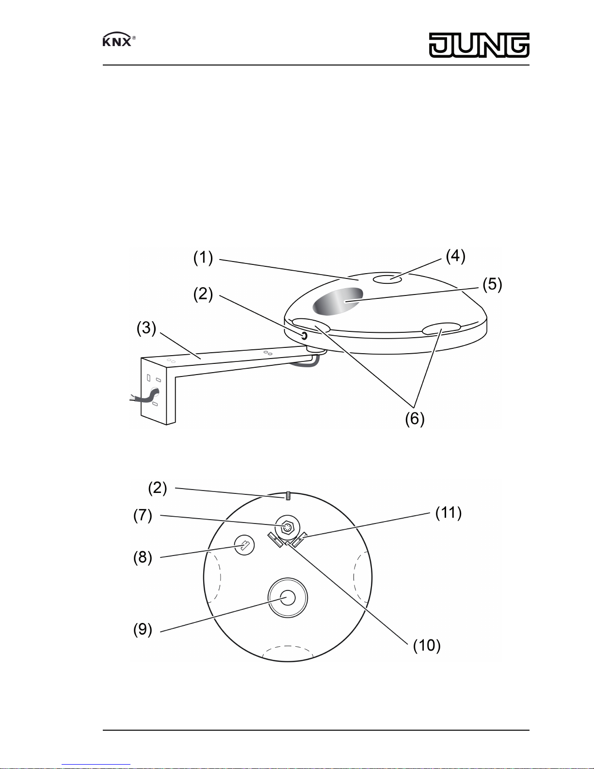
Jung 2225 WS U User manual

Universal weather station
Art. No. : 2225 WS U
Operating instructions
1 Safety instructions
Electrical equipment may only be installed and fitted by electrically skilled persons.
Serious injuries, fire or property damage possible. Please read and follow manual fully.
These instructions are an integral part of the product, and must remain with the end
customer.
2 Device components
Figure 1: View
Figure 2: Underside view
(1) Sensor head
(2) Grub screw for locking
1/9
82590103
J:0082590103 30.01.2015

(3) Fastening arm
(4) Global radiation sensor
(5) Precipitation sensor
(6) Light and twilight sensors
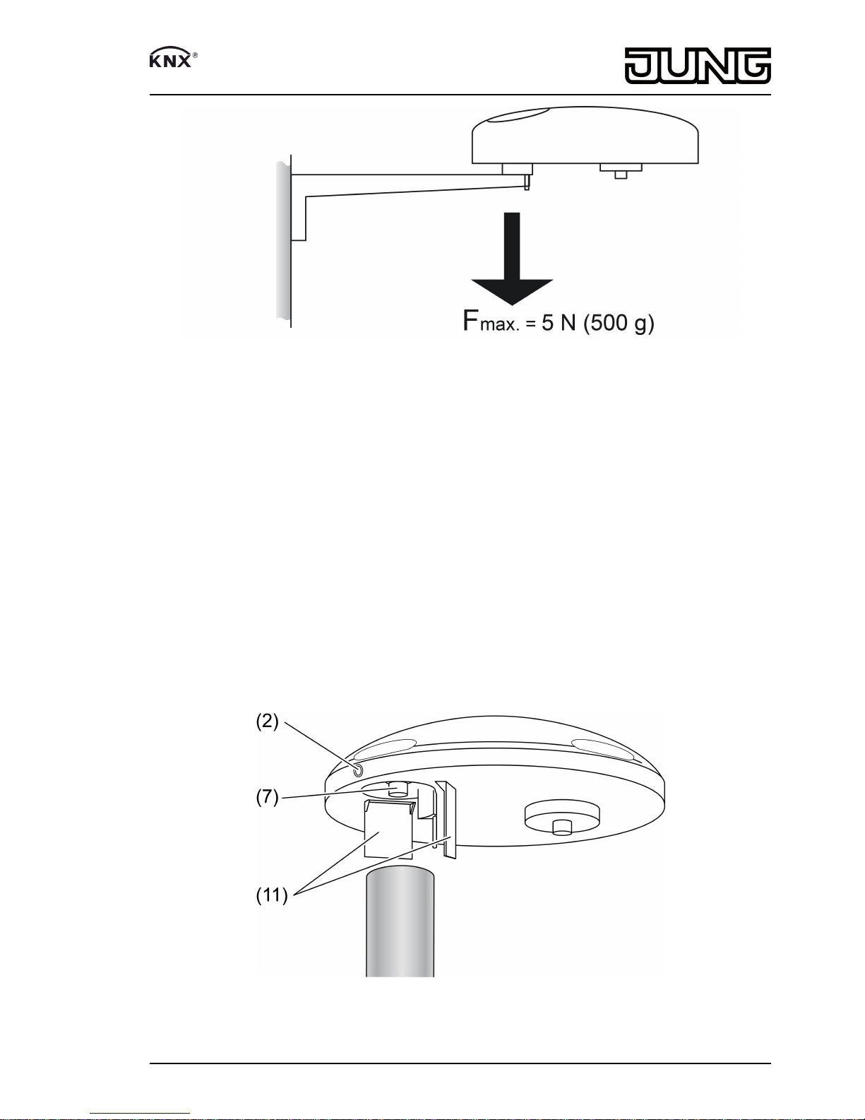
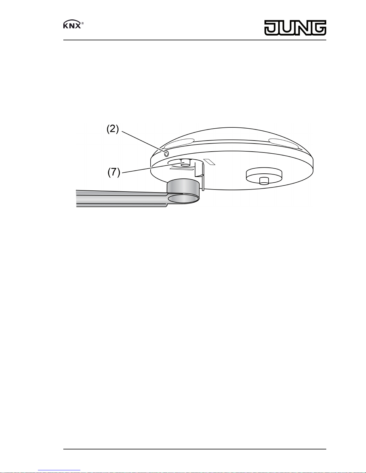
(7) Mounting for fastening arm with bus connection
(8) Air humidity sensor
(9) Wind speed and wind direction sensor
(10) Temperature sensor
(11) Guide blade
(only if mounted on a mast)
3 Function
System information
This device is a product of the KNX system and complies with the KNX directives. Detailed
technical knowledge obtained in KNX training courses is a prerequisite to proper understanding.
The function of this device depends upon the software. Detailed information on loadable
software and attainable functionality as well as the software itself can be obtained from the
manufacturer´s product database. Planning, installation and commissioning of the device are
carried out with the aid of KNX-certified software. The latest versions of product database and
the technical descriptions are available on our website.
Intended use
- Measurement and evaluation of weather data: Wind speed, Wind direction, Precipitation,
Brightness, Global radiation Twilight, Temperature, Relative air humidity and Air pressure
- Installation on the outside of buildings, preferable in the roof and facade area
- Operation with additional power supply (see accessories)
Product characteristics
- Integrated GPS/GLONASS receiver for automated positioning
- Calculation of additional weather data: Absolute air humidity, chill temperature, comfort
- Function for shading control
- Integrated KNX bus coupling unit
- Measurement data acquisition and limit value monitoring
- Software logic modules for linking events
- Integrated heating
iThe measured values apply to the mounting location. Variations to other weather services
– e.g. through local turbulence or areas with build-ups of air – are possible.
4 Information for electrically skilled persons
DANGER!
Electrical shock on contact with live parts in the installation environment.
Electrical shocks can be fatal.
Before working on the device, disconnect the power supply and cover up live
parts in the working environment.
2/9
82590103
J:0082590103 30.01.2015
Universal weather station

4.1 Fitting and electrical connection
Selecting the installation location
Figure 3: Minimum distance to surfaces
Figure 4: Avoid spray water
3/9
82590103
J:0082590103 30.01.2015
Universal weather station

Figure 5: Maximum load on the fastening arm
Select a mounting selection in which the weather station is not influenced by local obstacles or
shading, such as surrounding trees, chimneys, awnings, etc. The sensor must be able to detect
wind, rain and ambient brightness without impedance. Avoid slipstream, shadow casting and
light reflection.
Preferred mounting on a freestanding mast. If mounted on house walls, the measurement of
wind and brightness in particular can be distorted.
Do not mount it below or next to building sections, from which water can drip onto the device.
Select the mounting location so that the weather station will be accessible.
In the case of flat roofs, locate the weather station as close to the centre of the roof as possible.
Minimum distance to surfaces below the weather station: 0.6 m (figure 3). Otherwise, the
sensors on the underside may get damaged by penetrating spray water (figure 4).
Direct sunlight, chimneys or other waste gas or ventilation systems affect the temperature
measurement.
Do not operate in the vicinity of radio transmitter systems. Doing so will compromise function.
iDo not connect more than 3 weather stations in a KNX line.
Mounting weather station without fastening arm on freestanding mast
Figure 6: Mounting on freestanding mast without fastening arm
Use mast with outer diameter <25 mm and inner diameter >19 mm.
4/9
82590103
J:0082590103 30.01.2015
Universal weather station

oMount enclosed guide blade (11) in the fields provided next to the connection (7).
iIf mounted on a mast without the guide blade, no correct wind direction measurement is
possible due to the resulting turbulences.
oRoute the power supply line through the mast.
oAttach the 7-pin plug to the connection (7). Tighten threaded ring with max. 0.5 Nm.
oMount weather station onto the mast and align. The grub screw (2) must be pointing north.
oTighten grub screw (2) with max. 0.6 Nm.
Mounting weather station with fastening arm on mast or wall
Figure 7: Mounting with fastening arm
Mount enclosed fastening arm onto a suitable mast or wall.
The enclosed hose clamps are suitable up to a maximum mast diameter of 60 mm.
iIf mounted on the supplied fastening arm, do not mount the enclosed guide blade.
oMast mounting: Attach fastening arm to mounting mast using the enclosed hose clamps.
oWall mounting: Attach fastening arm to the wall through the boreholes (figure 8) using
suitable screws.
oRoute the power supply line along the underside of the fastening arm and guide the 7-pin
plug through the open pipe socket at the end of the fastening arm.
oAttach the 7-pin plug to the connection (7). Tighten threaded ring with max. 0.5 Nm.
oMount weather station onto the mast and align. The grub screw must be pointing north.
oTighten grub screw with max. 0.6 Nm.
oRoute the power supply line through the cable bushing into an installation pipe.
5/9
82590103
J:0082590103 30.01.2015
Universal weather station

Figure 8: Fastening arm – dimensions for boreholes
Mounting and connecting the device
oConnect bus line and external power supply to power supply line.
red KNX+
Black KNX–
orange + 24 V
brown GND
iThe sensor head is translucent. Therefore, do not stick or write on the sensor head.
Aligning the device
Figure 9: Orienting the weather station
oAlign the sensor head in the appropriate direction or - depending on the detailed on-site
circumstances - according to the alignment of the facade (figure 9).
6/9
82590103
J:0082590103 30.01.2015
Universal weather station

4.2 Commissioning
Commissioning the device
Figure 10: Position of the programming LED and reed contact
oSwitch on the bus voltage.
oSwitch on supply voltage.
oHold the supplied programming magnet by the integrated reed contact (12).
The programming LED (13) indicates the programming state blue.
oAssign physical addresses and load application software into the device.
oNote the physical address on adhesive labels on the underside.
The device is ready for operation.
5 Appendix
5.1 Technical data
Supply
Rated voltage AC 24 V SELV (± 10%)
Rated voltage DC 21 ... 32 V SELV
Current consumption 100 ... 400 mA
(dependent on the weather)
Protection class III
Connection cable
Cable type LiYCY 4xAWG26
Cable length 5 m
Total length per line 15 m
Number of weather stations max. 3 (per line)
KNX
KNX medium TP
Commissioning mode S-mode
Rated voltage KNX DC 21 ... 32 V SELV
Current consumption KNX max. 5 mA
Ambient conditions
Ambient temperature -30 ... +60 °C
Storage/transport temperature -25 ... +70 °C
Degree of protection IP 44 (in position for use)
Housing
Dimensions Ø×H 130×68 mm
Weight approx. 230 g
Wind direction sensor
Measuring range 1 ... 360°
7/9
82590103
J:0082590103 30.01.2015
Universal weather station

Resolution 1°
Accuracy ± 10 % (laminar wind stream)
Wind speed sensor
Measuring range approx. 0 ... 40 m/s
Resolution 0.1 m/s
Accuracy (≤ 10 m/s) ± 1 m/s
Accuracy (>10 m/s) ± 5 %
iAccuracy as RMS average value over 360°.
Temperature sensor
Measuring range -30 ... +60 °C
Resolution 0.1 K
Accuracy ± 1 C (Wind > 2 m/s, for -5 ... +25 °C)
Precipitation sensor
Measuring range yes/no
Accuracy Fine drizzle
Brightness sensors
Number 4
Measuring range approx. 0 ... 150 klx
Resolution 0.1 klx
Accuracy ± 3 %
Spectral range 475 ... 650 nm
Twilight sensor
Measuring range approx. 0 ... 900 lx
Resolution 1 lx
Accuracy ± 10 lx
Air pressure sensor
Measuring range 300 ... 1100 hPa
Resolution 0.01 hPa
Accuracy ± 0.5 hPa (20°C)
Humidity sensor
Measuring range 0 ... 100 % rel. humidity
Resolution 0.1 % rel. humidity
Accuracy ± 10 % rel. humidity (20°C)
abs. humidity 0 ... 400 g/m³
Resolution 0.01 g/m³
Global radiation
Measuring range 0 ... 1300 Watt/m²
Resolution 1 Watt/m²
Accuracy ± 10 %
Spectral range 350 ... 1100 nm
iAll accuracy specifications relate to the respective measuring range end value.
5.2 Accessories
Power supply AC 24 V ~ Art. No. WSSV10
5.3 Warranty
We reserve the right to make technical and formal changes to the product in the interest of
technical progress.
We provide a warranty as provided for by law.
Please send the device with a description of the defect to our central customer service office.
8/9
82590103
J:0082590103 30.01.2015
Universal weather station

ALBRECHT JUNG GMBH & CO. KG
Volmestraße 1
58579 Schalksmühle
Telefon: +49.23 55.8 06-0
Telefax: +49.23 55.8 06-2 04
www.jung.de
Service Center
Kupferstr. 17-19
44532 Lünen
Germany
9/9
82590103
J:0082590103 30.01.2015
Universal weather station
Table of contents
Other Jung Weather Station manuals