2. LOCATION OF PARTS AND CONTROLS
2.2.
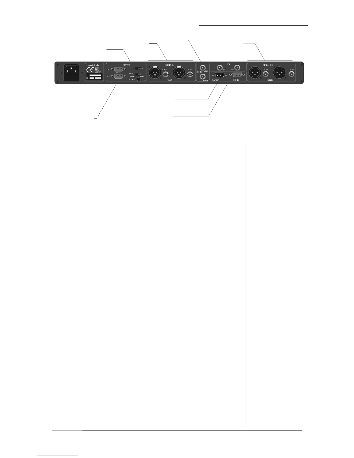
REAR PANEL
DIGITAL
OUTPUTS
DIGITAL
INPUTS
SYNC IN
BASIC
SETTINGS
SDI IN-/
OUTPUT
SERIAL
REMOTE
IN/OUT
GPI REMOTE
IN/OUT
fig. 2: rear panel b40
POWER INPUT
IEC mains input connector 230 V, 50 Hz (UK: 240 V, 50 Hz; JAPAN: 100 V,
60Hz; USA: 127 V, 60 Hz) with integrated fuse
REMOTE
serial remote interfacee RS-422
connector: 9pin SUB-D, input - male, output - female
GPI
paralle remote interface
TALLY-out TTL-level
connector: 9pin SUB-D, male
GPI-in TTL-level
connector: 9pin SUB-D, female
SYNC
AES/EBU input for ext. sync signal (AES 3 format, 75 Ohm, unbal)
connector: BNC socket
VIDEO input for video sync signal (blackburst, 75 Ohm, unbal)
connector: BNC socket
SDI IN / OUT (only for SDI-Version!)
Input/output for serial digital video (ITU-R BT.601, SMPTE 272M-A)
Format: • Video: 270 Mb/s, 525/625 line rate, 75 Ohm,
BNC socket
DIGITAL IN
input for AES/EBU standard format
connector: XLR female panel jack
1- ground, 2-3 signal, balanced
connector: BNC socket 75 Ohm, unbalanced
DIGITAL OUT
output for AES/EBU standard format
connector: XLR male panel jack
1- ground, 2-3 signal, balanced , 4 Vpp
connector: BNC socket 75 Ohm, unbalanced, 0.5V pp
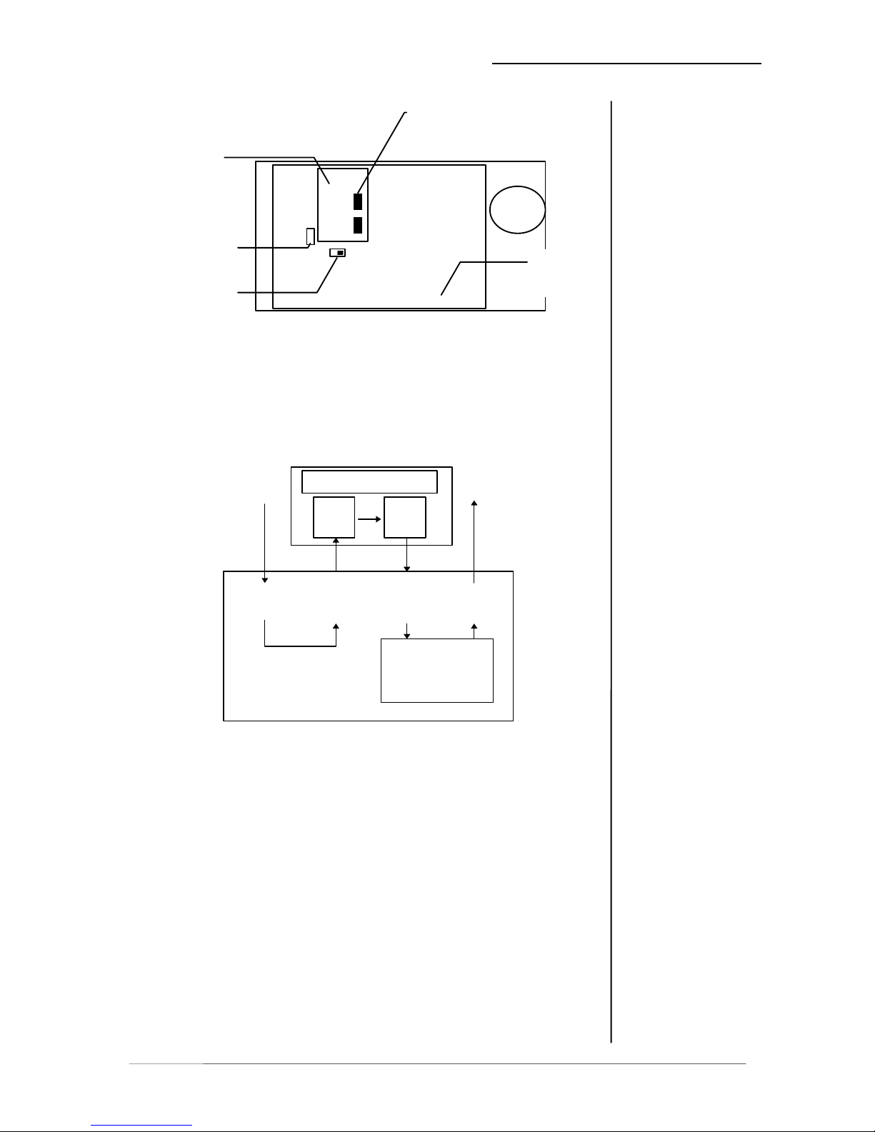
hardware bypass: relais are connecting related inputs and outputs if power
is failed
Operation manual b40, chapter 2 -control elements and displays- page 2-3