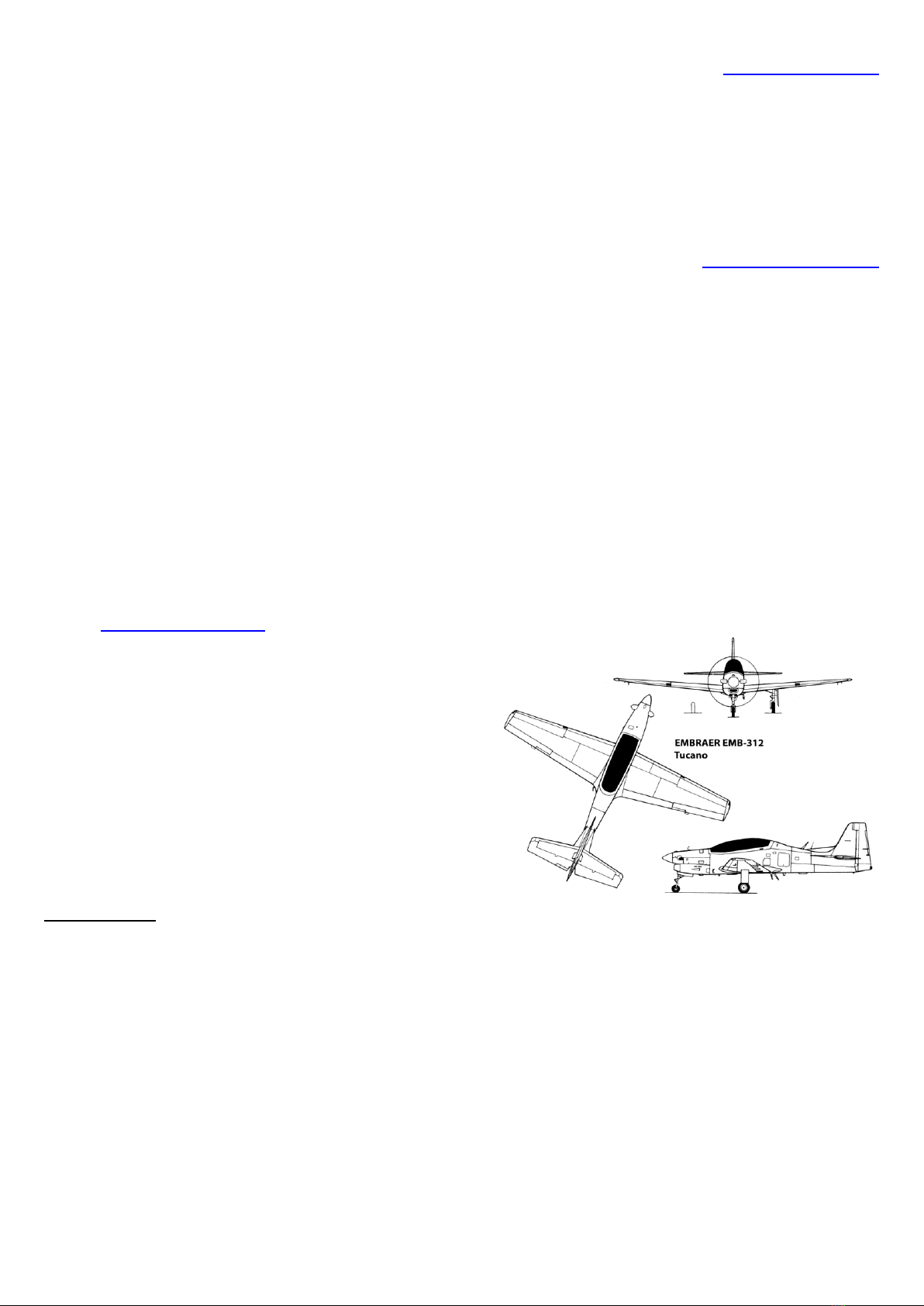
T-27 Tucano 20cc 1.2 2022
www.juniaer.com.br
3
This is the T-27 Tucano 20cc ARF Juniaer, prepared for retracts installation, with flaps, with an exquisite
finishing and many painting schemes available, very realistic and all detailed in relief, with rivets, antennas, side
door with hinge and lock (not installed), panel lines, compartments, pitot tubes replicas, landing gear doors,
paneled cockpit and clear canopy. Engine cowling in 2 parts with exhaust replicas. Model airplane made of high-
quality epoxy resin with structural reinforcements, low weight and high resistance due to the FULL COMPOSITE
high technology vacuum lamination technique. 2-piece wing (1 aluminum tube on the wing) laminated in
fiberglass and epoxy resin with carbon fiber reinforcements and laser-cut plywood and balsa structures.
Laminated stabilizer in fiberglass and epoxy resin with carbon fiber reinforcements and structures in plywood
and balsa laser cut in a single piece to be permanently glued to the fuselage. Clear canopy, resin made canopy
frame and cockpit with instruments panels. Ailerons, flaps e and elevators factory hinged in perfect align.
Rudder to be epoxy glued in 3 hinge points provided with the kit. Servo tray and fuel tank tray made of laser cut
plywood. Exquisite automotive painting finishing, scale decals and markings and varnished for long lasting.
Stable, realistic and acrobatic flight pattern. Capable of many maneuvers such as slow rolls, rolls, Cuban eights,
knife edge flight, inverted flight and much more. This model airplane was developed and built to provide a high
performance both for pleasant flights as for wealth of details and realism. It´s construction and made with
specific high-quality materials and advanced composite lamination techniques to provide low weight and high
structural strength.
The Juniaer model airplanes are painted and varnished with high quality and resistance products. Even so,
some care must be taken to protect the paint: wipe your model with a cloth immediately after use with water
sprays and neutral detergent. Fuels can damage the varnish if it penetrates punctures or damages to the plane's
surface, as well as cuts in the engine's cowling. To prevent this kind of problem, we recommend brushing two-
component PU varnish or applying epoxy to areas that are uncovered for any reason. Avoid exposing the model
to direct sunlight as much as possible, especially the darker painted parts that accumulate and reflect a greater
amount of heat, causing an internal and external temperature raising. The use of automotive wax for polishing
is useful in preventing the accumulation of dirt and facilitates the cleaning and protection of the varnish. We
suggest the use of fabric smooth covers for storage and transport, in order to protect against damage and risks.
Be careful when handling your model airplane, especially the movable control surfaces. Never lift it by the two
wing tips only, as the total weight is considerable to be supported only by 2 distant points. When checking the
model airplane´s balance through the center of gravity (C.G.) always support it by the roots of the wing at the
indicated points.
Please read this manual to the end before doing anything on your model airplane, it contains important
information regarding assembly and use, and it will also give you an overview of what should be done correctly
and following the guidelines.
Please check and identify all parts of your model airplane when you receive it. If any parts are damaged or
defective, please contact our customer service. Your model aircraft has a 90-day factory warranty against
manufacturing defects. Juniaer Model Airplanes guarantees that this kit is free from manufacturing defects in
both material and workmanship at the date of purchase. This warranty does not cover any components
damaged by use or modifications. In no event will Juniaer's liability exceed the original cost of the kit purchased.
In addition, Juniaer Model Airplanes reserves the right to change this warranty without prior notice. Since
Juniaer Model Airplanes has no control over the final assembly or the equipment used for the final assembly,
no liability will be assumed or accepted for any damages resulting from the user's use of the final product
assembled by him or third parties. Through the act of using the assembled product by the user, he accepts all
responsibility for the result. If the buyer is not prepared to accept responsibility for the use of this product, it
must be returned immediately to the place of purchase in new and unused condition. This product is intended
for persons over 18 years old and any procedure involved in its assembly and use must be monitored by an
adult.