Juniper MX960 User manual

MX960 Ethernet Services Router
DC Power Supply
Installation Instructions
19 October 2007
Part Number: 530-017577-01
Revision 2
This document describes how to remove and replace a DC power supply on a Juniper
Networks MX960 Ethernet Services Router.
Contents DC Power Supply ............................................................................................2
DC Power Supply Electrical Specifications ................................................2
DC Power Supply LEDs .............................................................................3
Replacing a DC Power Supply .........................................................................4
Removing a DC Power Supply ..................................................................4
Installing a DC Power Supply ....................................................................7
List of Technical Publications ........................................................................10
Requesting Support .......................................................................................16
Revision History ............................................................................................16
■1
DC Power Supply
In the DC power configuration, the router contains either two or four DC power
supplies (see Figure 1 on page 2), located at the lower rear of the chassis in
slots PEM0 through PEM3 (left to right). You can upgrade your DC power system from
two to four power supplies. The DC power supplies in slots PEM0 and PEM2 provide
power to the lower fan tray, DPC slots 6through 11, and SCB slots 1and 2. The DC
power supplies in slots PEM1 and PEM3 provide power to the upper fan tray, DPC
slots 0through 5, and SCB slot 0.
Four power supplies provide full redundancy. If a DC power supply fails, its redundant
power supply takes over without interruption.
Each DC power supply has a single DC input (–48 VDC and return) that requires a
dedicated 80 A (–48 VDC) circuit breaker for the maximum router hardware
configuration. For information about site power preparations and connecting the
router to power and ground, see the MX960 Ethernet Services Router Hardware Guide.
For DC power supply and power system electrical specifications, see Table 1 on page
3 and the MX960 Ethernet Services Router Hardware Guide.
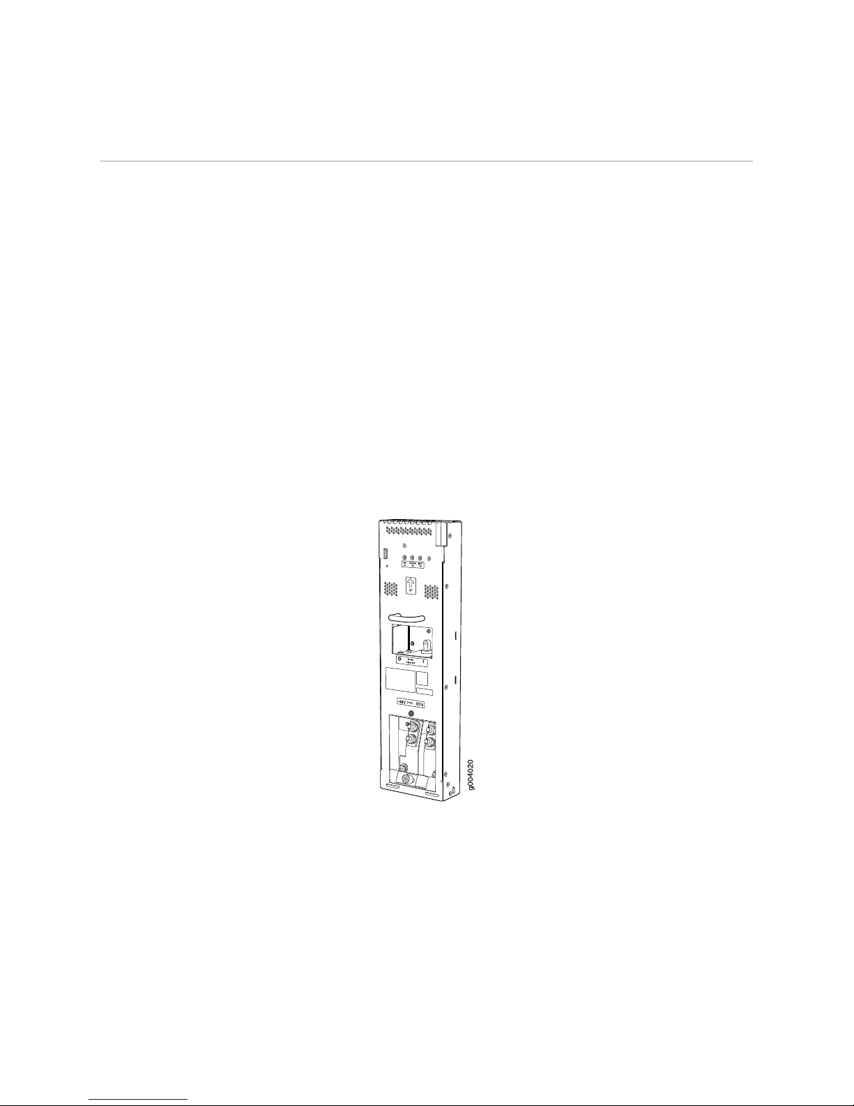
Figure 1: DC Power Supply
DC Power Supply Electrical Specifications
Table 1 on page 3 lists the DC power supply electrical specifications. For DC power
system electrical specifications, see the MX960 Ethernet Services Router Hardware
Guide.
2■DC Power Supply
MX960 Ethernet Services Router DC Power Supply Installation Instructions

Table 1: DC Power Supply Electrical Specifications
SpecificationItem
2800 WMaximum output power
Minimum: –40 VDC
Nominal: –48 VDC
Operating range: –40 to –72 VDC
NOTE: If the input voltage from the DC power source drops below
-37.5 to -39.5 VDC, the routing platform automatically shuts down.
During automatic shutdown, the circuit remains active. When the
input voltage returns to –43.0 to –44.00 VDC, the router
automatically starts up again and the system returns to normal
operation within 30 minutes. No operator intervention is required.
DC input voltage
70 A maximum @ –48 VDC (nominal operating voltage)DC input current rating
80 AInternal Supplementary
Protector
DC Power Supply LEDs
Each DC power supply faceplate contains three LEDs that indicate the status of the
power supply (see Table 2 on page 3). The power supply status is also reflected in
two LEDs on the craft interface (see the MX960 Ethernet Services Router Hardware
Guide). In addition, a power supply failure triggers the red alarm LED on the craft
interface.
Table 2: DC Power Supply LEDs
DescriptionStateColorLabel
Power supply is not functioning normally. Check the INPUT OK LED for more
information.
OffGreen
PWR OK
Power supply is functioning normally.On
DC power supply circuit breaker is turned off.OffGreen
BREAKER
ON
DC power supply circuit breaker is turned on.On
DC input to the PEM is not present.OffGreen
INPUT OK
DC input is present, and is connected in correct polarity.On
DC input is present, but connected in reverse polarity.OnAmber
DC Power Supply ■3
DC Power Supply

Replacing a DC Power Supply
To replace a DC power supply, use the following procedures:
■Removing a DC Power Supply on page 4
■Installing a DC Power Supply on page 7
Removing a DC Power Supply
The power supplies are located at the rear of the chassis. Each DC power supply
weighs approximately 3.8 lb (1.7 kg).
CAUTION: Do not leave a power supply slot empty for more than 30 minutes while
the router is operational. For proper airflow, the power supply must remain in the
chassis or a blank panel must be used in an empty slot.
NOTE: After powering off a power supply, wait at least 60 seconds before turning it
back on.
To remove a DC power supply, follow this procedure:
1. Make sure that the voltage across the DC power source cable leads is 0 V and
that there is no chance that the cables might become active during the removal
process.
2. Attach an electrostatic discharge (ESD) grounding strap to your bare wrist and
connect the strap to one of the ESD points on the chassis. For more information
about ESD, see the MX960 Ethernet Services Router Hardware Guide.
3. Switch the circuit breaker on the power supply faceplate to the OFF position.
4. Remove the clear plastic cover protecting the terminal studs on the faceplate.
5. Remove the nuts and washers from the terminal studs (see Figure 2 on page 5).
(Use a 3/8–in. nut driver or pliers.)
4■Replacing a DC Power Supply
MX960 Ethernet Services Router DC Power Supply Installation Instructions

Figure 2: Disconnecting Power Cables From the DC Power Supply
6. Remove the cable lugs from the terminal studs.
7. Loosen the captive screw on the cable restraint on the lower edge of the power
supply faceplate.
8. Carefully move the power cables out of the way.
9. While grasping the handle on the power supply faceplate with one hand, use
your other hand to pull the spring-loaded locking pin in the release lever away
from the chassis and turn the release lever counterclockwise until it stops (see
Figure 3 on page 6).
10. Let go of the locking pin in the release lever. Ensure that the pin is seated inside
the corresponding hole in the chassis.
11. Pull the power supply straight out of the chassis.
WARNING: Do not touch the power connector on the top of the power supply (see
Figure 4 on page 6). It can contain dangerous voltages.
Replacing a DC Power Supply ■5
Replacing a DC Power Supply

Figure 3: Removing a DC Power Supply
Figure 4: Top of the Power Supply Showing Midplane Connector
6■Replacing a DC Power Supply
MX960 Ethernet Services Router DC Power Supply Installation Instructions

Installing a DC Power Supply
To install a DC power supply, follow this procedure (see Figure 5 on page 9):
1. Ensure that the voltage across the DC power source cable leads is 0 V and that
there is no chance that the cable leads might become active during installation.
CAUTION: You must ensure that power connections maintain the proper polarity.
The power source cables might be labeled (+) and (–)to indicate their polarity. There
is no standard color coding for DC power cables. The color coding used by the external
DC power source at your site determines the color coding for the leads on the power
cables that attach to the terminal studs on each power supply.
2. Attach an electrostatic discharge (ESD) grounding strap to your bare wrist and
connect the strap to one of the ESD points on the chassis. For more information
about ESD, see the MX960 Ethernet Services Router Hardware Guide.
3. Switch the circuit breaker on the power supply faceplate to the OFF position.
4. Ensure that the release lever below the empty power supply slot is engaged in
the counterclockwise, or unlocked, position (see Figure 5 on page 9).
If necessary, pull the spring-loaded locking pin in the release lever away from
the chassis and turn the release lever counterclockwise until it stops. Let go of
the locking pin in the release lever. Ensure that the pin is seated inside the
corresponding hole in the chassis.
5. Using both hands, slide the power supply straight into the chassis until the power
supply is fully seated in the chassis slot. The power supply faceplate should be
flush with any adjacent power supply faceplates.
The small tab on the metal housing that is controlled by the release lever must
be inside the corresponding slot at the bottom of the power supply (see
Figure 5 on page 9). This tab is used to pull the power supply down in the
chassis slot, before the power supply is removed.
6. While firmly pushing the handle on the power supply faceplate with one hand,
use your other hand to pull the spring-loaded locking pin in the release lever
away from the chassis and turn the release lever clockwise until it stops.
7. Let go of the locking pin in the release lever. Ensure that the pin is seated inside
the corresponding hole in the chassis.
8. Remove the clear plastic cover protecting the terminal studs on the faceplate.
9. Remove the nuts and washers from the terminal studs.
10. Attach the lugs on the DC source power cables to the terminal studs, making
sure the cables are not touching or in the way of any router components (see
Figure 6 on page 10).
Replacing a DC Power Supply ■7
Replacing a DC Power Supply

■Attach the positive (+) DC source power cable lug to the RTN (return)
terminal.
■Attach the negative (–) DC source power cable lug to the –48V (input)
terminal.
NOTE: The DC power supplies in slots PEM0 and PEM1 must be powered by dedicated
power feeds derived from feed A, and the DC power supplies in slots PEM2 and PEM3
must be powered by dedicated power feeds derived from feed B. This configuration
provides the commonly deployed A/B feed redundancy for the system. For
information about connecting to DC power sources, see the MX960 Ethernet Services
Router Hardware Guide.
11. Secure each power cable lug to the terminal studs, first with the split washer,
then with the nut. Apply between 23 lb-in. (2.6 Nm) and 25 lb-in. (2.8 Nm) of
torque to each nut.
12. Loosen the captive screw on the cable restraint on the lower edge of the power
supply faceplate.
13. Route the positive and negative DC power cables through the left and right sides
of the cable restraint.
14. Tighten the cable restraint captive screw to hold the power cables in place.
15. Replace the clear plastic cover over the terminal studs on the faceplate.
16. Verify that the ground and power cabling are correct, that they are not touching
or blocking access to router components, and that they do not drape where
people could trip on them.
17. Switch the circuit breaker on the power supply to the ON position and observe
the status LEDs on the power supply faceplate. If the power supply is correctly
installed and functioning normally, the PWR OK, BREAKER ON, and INPUT OK
LEDs light steadily.
8■Replacing a DC Power Supply
MX960 Ethernet Services Router DC Power Supply Installation Instructions
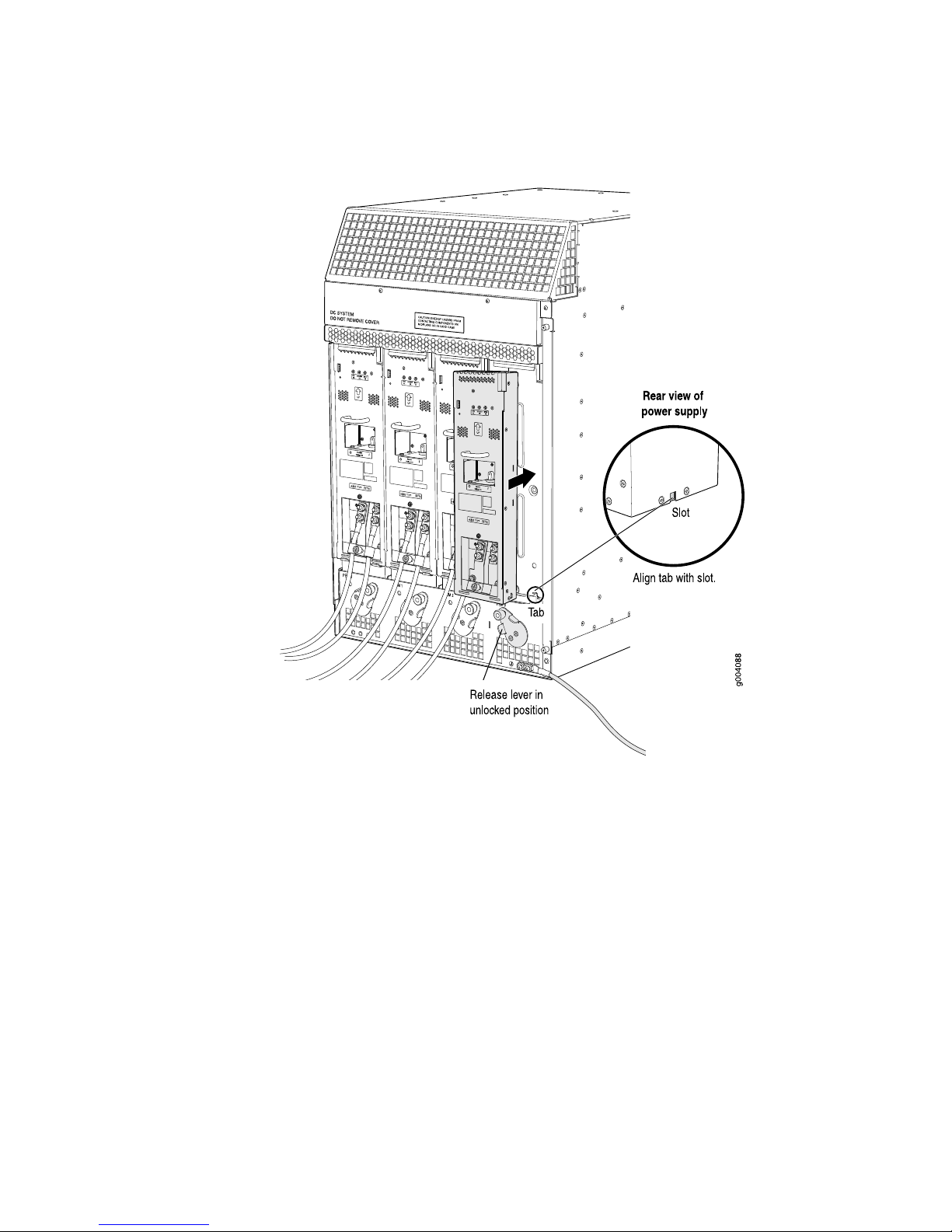
Figure 5: Installing a DC Power Supply
Replacing a DC Power Supply ■9
Replacing a DC Power Supply
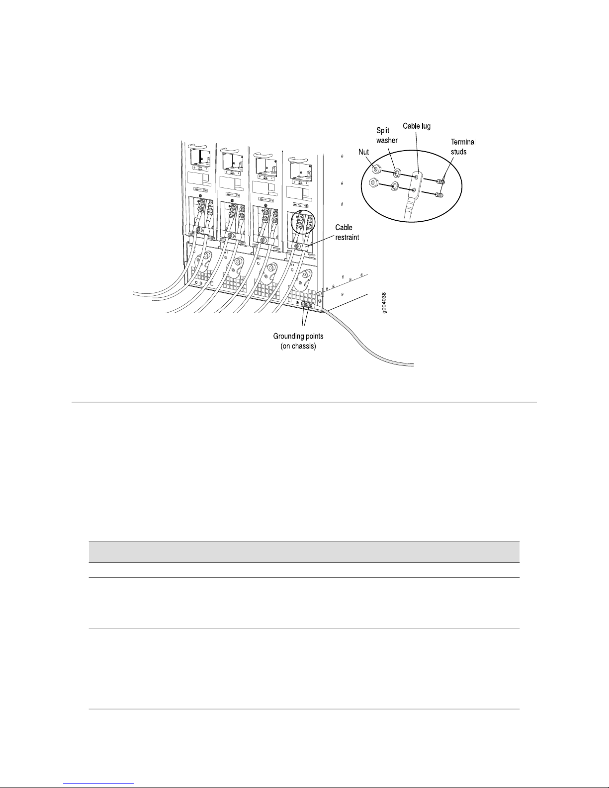
Figure 6: Connecting DC Power to the Router
List of Technical Publications
Table 3 on page 10 lists the software and hardware guides and release notes for
Juniper Networks J-series, M-series, MX-series, and T-series routing platforms and
describes the contents of each document. Table 4 on page 15 lists the books included
in the Network Operations Guide series.
Table 5 on page 15 lists additional books on Juniper Networks solutions that you can
order through your bookstore. A complete list of such books is available at
http://www.juniper.net/books.
Table 3: Technical Documentation for Supported Routing Platforms
DescriptionBook
JUNOS Software for Supported Routing Platforms
Explains how to configure access privileges in user classes by using
permission flags and regular expressions. Lists the permission flags
along with their associated command-line interface (CLI) operational
mode commands and configuration statements.
Access Privilege
Provides an overview of the class-of-service (CoS) functions of the
JUNOS software and describes how to configure CoS features,
including configuring multiple forwarding classes for transmitting
packets, defining which packets are placed into each output queue,
scheduling the transmission service level for each queue, and
managing congestion through the random early detection (RED)
algorithm.
Class of Service
10 ■List of Technical Publications
MX960 Ethernet Services Router DC Power Supply Installation Instructions
Other manuals for MX960
6
Table of contents
Other Juniper Power Supply manuals


