manuals.online logo
Brands
  1. Home
  2. •
  3. Brands
  4. •
  5. Juniper
  6. •
  7. Switch
  8. •
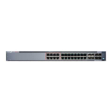
  9. Juniper OCX1100-48SX User manual

Juniper OCX1100-48SX User manual

OCX1100-48SX Switch Quick Start
See the complete OCX Series documentation at
www.juniper.net/techpubs/en_US/release-independent/junos/
information-products/pathway-pages/ocx-series/product/ .
To install and perform initial configuration of a Juniper Networks®
OCX1100-48SX Switch, you need:
zAn electrostatic discharge (ESD) grounding strap (not provided)
zOne pair of front rack-mounting brackets (provided)
zOne pair of rack-mounting slider brackets (provided)
zEight Phillips-head front rack-mounting bracket screws (provided)
zEight rack-mounting screws (not provided)
zOne screwdriver appropriate for your rack-mounting screws (not provided)
zTwo AC power cords for AC powered switch models (with plugs appropriate for your
geographical location) or two DC powers cords for DC powered switch models
zRJ-45 cable and RJ-45 to DB-9 serial port adapter (provided)
zUSB2.0 AF-MICOR AM 150MM BLK cable (provided)
zManagement host, such as a PC, with an Ethernet port (not provided)
Register product serial numbers on the Juniper Networks website at
https://tools.juniper.net/svcreg/SRegSerialNum.jsp and update the installation base data
at https://www.juniper.net/customers/csc/management/updateinstallbase.jsp if there is
any addition or change to the installation base or if the installation base is moved.
Juniper Networks will not be accountable for not meeting the hardware replacement
service-level agreement for products that do not have registered serial numbers or
accurate installation base data.
WARNING: Ensure that you understand how to prevent ESD damage. Attach the
ESD grounding strap to your bare wrist, and connect the strap to the ESD point on
the chassis.
Part 1: Mount the Switch on Four Posts of a Rack
You can mount the switch on four posts of a 19-in. rack or cabinet by using the
rack-mounting brackets provided with the switch. Two persons are required for this
procedure.
1. Place the rack or cabinet in its permanent location, allowing adequate clearance for
airflow and maintenance, and secure it to the building structure.
NOTE: While mounting multiple units on a rack, mount the heaviest unit at the bottom
and mount the other units from the bottom to the top in decreasing order of weight.
2. Align the holes on the front rack-mounting bracket with the screw holes on the side of
the chassis and attach the front rack-mounting bracket to the switch by using the front
rack-mounting bracket screws.
NOTE: Installing the switch requires one person to lift it and a second person to secure it
to the rack.
3. Align the holes on the rack-mounting
slider bracket with the screw holes
on the back of the rack posts.
4. Attach the rack-mounting slider
brackets to the rack posts by using
rack-mounting screws. The ears of
the bracket must be facing backward
and outward.
5. Position the switch so that the
rack-mounting slider brackets align
horizontally within the two rows of
rack-mounting slider bracket pegs
located on the side panel of the
switch.
6. Slide the switch backwards so that
the rack-mounting slider brackets fit
into the space between the two rows
of rack-mounting slider pegs.
7. Have a second person secure the
front rack-mounting brackets to the
front of the rack posts by using
rack-mounting screws. Tighten the
screws.
8. Ensure that the switch chassis is
level by verifying that all the screws
on the front of the rack are aligned
with the screws on the back of the
rack.
Part 2: Connect Power to the Switch
CAUTION:
Do not mix or install:
zAC and DC power supplies in the same chassis.
zPower supplies and fan modules with different airflow labels (AIR IN (AFI) and AIR
OUT (AFO)) in the same chassis.
The switch is shipped with power supplies pre-installed, either AC or DC, depending on
the switch model.
1. If the power source outlet has a power switch, set it to the OFF (0) position.
2. Insert the coupler end of the power cord into the power port of the power supply
module.
3. Connect the power cord plug into the power source outlet.
4. If the power source outlet has a power switch, set it to the ON (|) position.
g000665
g000666
g000667
Juniper Networks, Junos, Steel-Belted Radius, NetScreen, and ScreenOS are registered trademarks of Juniper Networks, Inc. in the United States and other countries. The Juniper Networks Logo, the Junos logo, and JunosE are
trademarks of Juniper Networks, Inc. All other trademarks, service marks, registered trademarks, or registered service marks are the property of their respective owners. Juniper Networks assumes no responsibility for any inaccuracies
in this document. Juniper Networks reserves the right to change, modify, transfer, or otherwise revise this publication without notice. Products made or sold by Juniper Networks or components thereof might be covered by one or more
of the following patents that are owned by or licensed to Juniper Networks: U.S. Patent Nos. 5,473,599, 5,905,725, 5,909,440, 6,192,051, 6,333,650, 6,359,479, 6,406,312, 6,429,706, 6,459,579, 6,493,347, 6,538,518, 6,538,899,
6,552,918, 6,567,902, 6,578,186, and 6,590,785. Copyright © 2013, Juniper Networks, Inc. All rights reserved. Part Number: 530-061741, Revision 01, March 2015.
Part 3: Perform Initial Configuration
You must perform the initial configuration of the switch through the console port. Before
you begin, set the following parameter values in the console server or PC:
zbaud rate—115200;
zflow control—none;
zdata—8;
zparity—none;
zstop bits—1;
zDCD state—disregard.
To connect and configure the switch:
1. Connect the console port on the rear panel of the switch to a laptop or PC by using
the RJ-45 to DB-9 serial port adapter.
2. Log in as root. There is no password. If the software booted before you connected
to the console port, press the Enter key for the prompt to appear.
login: root
3. Start the CLI.
root@:RE:0% cli
4. Enter configuration mode.
root> configure
5. Specify a password for the root administration user account.
[edit]
root@# set system root-authentication plain-text-password
New password: password
Retype new password: password
6. (Optional) Configure the name of the switch. If the name includes spaces, enclose
the name in quotation marks (“ ”).
[edit]
root@# set system host-name host-name
7. Configure the default gateway.
[edit]
root@# set routing-options static route default next-hop address
8. Configure the IP address and prefix length for the switch management interface.
[edit]
root@# set interfaces em0 unit 0 family inet address address/prefix-length
9. (Optional) Configure the static routes to remote prefixes with access to the
management port.
[edit]
root@# set routing-options static route remote-prefix next-hop destination-ip retain no-readvertise
10. Enable ssh service.
[edit]
root# set system services ssh root-login allow
11. Commit the configuration.
[edit]
root@# commit
Safety Warnings Summary
This is a summary of safety warnings. For a complete list of warnings, including
translations, see the OCX Series documentation at
https://www.juniper.net/techpubs/en_US/release-independent/junos/information-product
s/pathway-pages/ocx-series/product/ .
WARNING: Failure to observe these safety warnings can result in personal injury
or death.
zPermit only trained and qualified personnel to install or replace switch components.
zPerform only the procedures described in this quick start and the OCX Series
documentation. Other services must be performed only by authorized service
personnel.
zBefore installing the switch, read the planning instructions in the OCX Series
documentation to make sure that the site meets power, environmental, and clearance
requirements for the switch.
zBefore connecting the switch to a power source, read the installation instructions in the
OCX Series documentation.
zInstalling the switch requires one person to lift the switch and a second person to
install the mounting screws.
zIf the rack has stabilizing devices, install them in the rack before mounting or servicing
the switch in the rack.
zBefore installing or after removing an electrical component, always place it
component-side up on an antistatic mat placed on a flat, stable surface or in an
antistatic bag.
zDo not work on the switch or connect or disconnect cables during electrical storms.
zBefore working on equipment that is connected to power lines, remove jewelry,
including rings, necklaces, and watches. Metal objects heat up when connected to
power and ground and can cause serious burns or become welded to the terminals.
Power Cable Warning (Japanese)
The attached power cable is only for this product. Do not use this cable for another
product.
Contacting Juniper Networks
For technical support, see http://www.juniper.net/support/requesting-support.html .
g017253

Other Juniper Switch manuals

Juniper EX2200 Series Installation instructions

Juniper

Juniper EX2200 Series Installation instructions

Juniper EX3200 Series User manual

Juniper

Juniper EX3200 Series User manual

Juniper EX2200 Series Installation instructions

Juniper

Juniper EX2200 Series Installation instructions

Juniper EX9251 Installation instructions

Juniper

Juniper EX9251 Installation instructions

Juniper EX Series Instruction Manual

Juniper

Juniper EX Series Instruction Manual

Juniper QFX5200-48Y User manual

Juniper

Juniper QFX5200-48Y User manual

Juniper EX 3200 User manual

Juniper

Juniper EX 3200 User manual

Juniper EX 3200 24T User manual

Juniper

Juniper EX 3200 24T User manual

Juniper EX Series Guide

Juniper

Juniper EX Series Guide

Juniper EX8200 Series User manual

Juniper

Juniper EX8200 Series User manual

Juniper EX8208 User manual

Juniper

Juniper EX8208 User manual

Juniper EX9253 Installation instructions

Juniper

Juniper EX9253 Installation instructions

Juniper QFX10002 User manual

Juniper

Juniper QFX10002 User manual

Juniper EX8200 Series Instruction Manual

Juniper

Juniper EX8200 Series Instruction Manual

Juniper EX4550 User manual

Juniper

Juniper EX4550 User manual

Juniper EX8200 Series Quick start guide

Juniper

Juniper EX8200 Series Quick start guide

Juniper QFX5200 Installation instructions

Juniper

Juniper QFX5200 Installation instructions

Juniper QFX5220 Installation instructions

Juniper

Juniper QFX5220 Installation instructions

Juniper EX Series User manual

Juniper

Juniper EX Series User manual

Juniper EX4500 Series User manual

Juniper

Juniper EX4500 Series User manual

Juniper EX 4200 24F User manual

Juniper

Juniper EX 4200 24F User manual

Juniper QFX3000-G QFabric Operator's manual

Juniper

Juniper QFX3000-G QFabric Operator's manual

Juniper EX9208 Installation instructions

Juniper

Juniper EX9208 Installation instructions

Juniper EX4100 User manual

Juniper

Juniper EX4100 User manual

Popular Switch manuals by other brands

Alloy AWPS-8T1SFP Quick install guide

Alloy

Alloy AWPS-8T1SFP Quick install guide

Westermo SDW-500 user guide

Westermo

Westermo SDW-500 user guide

Dell PowerConnect B-TI24x Hardware installation guide

Dell

Dell PowerConnect B-TI24x Hardware installation guide

Mellanox Technologies SX1710 user manual

Mellanox Technologies

Mellanox Technologies SX1710 user manual

Dell PowerVault 56F user guide

Dell

Dell PowerVault 56F user guide

Impact Acoustics 40921 user manual

Impact Acoustics

Impact Acoustics 40921 user manual

ANTAIRA LNP-0500G Series user manual

ANTAIRA

ANTAIRA LNP-0500G Series user manual

Radial Engineering J48 stereo user guide

Radial Engineering

Radial Engineering J48 stereo user guide

Spartan SP-TS4500PLUS user manual

Spartan

Spartan SP-TS4500PLUS user manual

Sonoff ZigBee DIY BASICZBR3 user manual

Sonoff

Sonoff ZigBee DIY BASICZBR3 user manual

axing SES 984-06 Operation instructions

axing

axing SES 984-06 Operation instructions

Häfele Smart ZigBee switch user manual

Häfele

Häfele Smart ZigBee switch user manual

LevelOne KVM-0260 user manual

LevelOne

LevelOne KVM-0260 user manual

IDK MSD-701UHD Command reference guide

IDK

IDK MSD-701UHD Command reference guide

AIVO NETWORKS AVN-S09-1P08W135G user manual

AIVO NETWORKS

AIVO NETWORKS AVN-S09-1P08W135G user manual

StarTech.com StarView SV1631D user manual

StarTech.com

StarTech.com StarView SV1631D user manual

GE ZW4106 manual

GE

GE ZW4106 manual

Siemens SIMATIC NET RUGGEDCOM RMC40 installation manual

Siemens

Siemens SIMATIC NET RUGGEDCOM RMC40 installation manual

manuals.online logo
manuals.online logoBrands
  • About & Mission
  • Contact us
  • Privacy Policy
  • Terms and Conditions

Copyright 2025 Manuals.Online. All Rights Reserved.