Juntek JDS2800-60M User manual

JDS2800 series
Dual-Channel
Function/Arbitrary
DDSSignalGenerator
Rev1.0
Quick S t a r t Guide

2
Hangzhou Junce Instrument Co., Ltd.
Contents
Chapter 1 Overview .........................................4
1, Instrument introduction ...................................4
2, Model description .........................................4
3, Dimension .................................................5
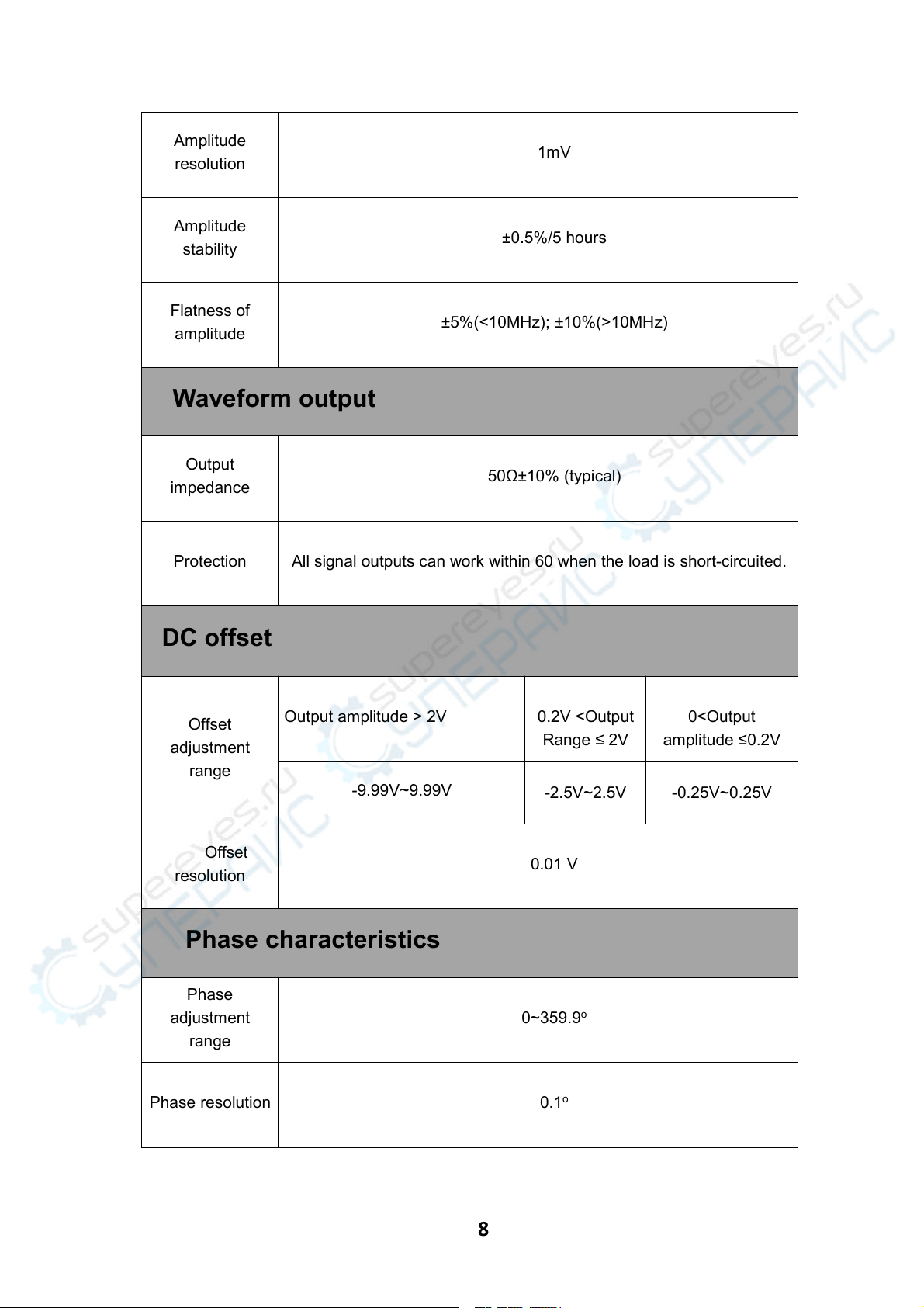
4, Technical parameters ......................................5
Chapter II Instrument Description ............................11
1, Front panel overview ......................................11
2, Display interface description .............................13
3.The key function description ...............................14
Chapter III Instrument Operation Instructions ...............15
1, Setting parameters and outputting waveforms in the main
interface ........................................................15
2, MEAS measurement mode interface parameter settings ........16
3, MOD modulation mode interface parameter settings ..........16
4, System settings interface, parameter settings .............18

3
Check
When you get a new JDS2800 series dual-channel signal generator, it is recommended
that you follow the steps below to check the instrument.
Check the package
If the package is damaged, keep the damaged packaging or shockproof material until the
goods have been fully inspected and the instrument has passed electrical and
mechanical tests. If the instrument is damaged due to shipping, please contact the
shipper and the carrier for compensation.
Check accessories
The contents of accessories are as follows. If the contents do not match or the
instrument is damaged, contact the dealer or the company.
Host: JDS2800 Series Dual Channel
Signal Generator
1pcs
Accessories: Power Adapter
1pcs
USB cable
1pcs
Signal connection cable
2pcs
User manual
1pcs
CD
1pcs
Check the whole machine
If you find that the instrument is damaged, the instrument is not working properly, or fails
the performance test, contact your dealer or our company.
TEL:0371-86106382 QQ1: 1406921960 QQ2: 3155097720
Mail: 1406921960@qq.com,
3155097720@qq.com
R&D company: Hangzhou Junce Instrument Co., Ltd. WEB:www.junteks.com

4
Chapter 1 Overview
Instrument introduction
JDS2800 series function generator can generate multiple waveforms such as sine wave,
square wave, triangle wave, pulse wave, and arbitrary wave. The frequency range up to
60MHz, with duty cycle adjustment, sweep frequency, frequency signal frequency and
counter function, and the output signal, amplitude, and frequency can be displayed
simultaneously. The series signal generator has excellent amplitude and frequency
characteristics, the appearance of this instrument is exquisite and beautiful.
This instrument is widely used in factories, schools, research institutes and laboratories.
The model description
This series of instruments are divided into three models, the main difference is the
maximum frequency of sine wave output, as described below:
Model
Sine wave output maximum frequency
JDS2800-60M
60MHz
JDS2800-40M
40MHz
JDS2800-15M
15MHz

5
Dimension
Note: unit mm
Technical parameters
Frequency characteristics
JDS2800
-15M
JDS2800
-40M
JDS2800
-60M
Sine wave
frequency range
0~15MHz
0~40MHz
0~60MHz
Square wave
frequency range
0~15MHz
0-25MHz
0-25MHz
Triangle wave
frequency range

6
Pulse wave
frequency range
0~6MHz
0~6MHz
0~6MHz
TTL digital wave
frequency range
Arbitrary
frequency range
Pulse width
adjustment
range
100nS~4000S
40nS~4000S
25nS~4000S
Square wave
rise time
≤25ns
≤10ns
≤10ns
Minimum
frequency
resolution
0.01uHz(0.00000001Hz)
Frequency
accuracy
±20ppm
Frequency
stability
±1ppm/3hours
±1ppm/3 hours
Waveform characteristics
Waveform
type
Sine、Square、pulse (adjustable duty cycle, precise adjustment
of pulse width and period), triangular wave, partial sine wave, CMOS
wave, DC level (set DC amplitude by adjusting offset), half wave, full
Wave, positive staircase wave, anti-ladder wave, noise wave,
exponential rise, exponential drop, multisonic wave, Symplectic pulse
and Lorenz pulse and 60 arbitrary waveforms
Wave length
2048 points
Waveform
sampling rate
266MSa/s

7
Waveform
vertical
resolution
14-bits
Sine wave
Harmonic Suppression
≥45dBc(<1MHz);
≥40dBc(1MHz~20MHz)
Total harmonic distortion
<0.8%(20Hz~20kHz,0dBm)
Square wave
and pulse wave
Overshoot
≤5%
Pulse wave
Duty cycle adjustment range
0.1%~99.9%
Partial sine wave
Duty cycle adjustment range
0.1%~99.9%
Sawtooth wave
Linearity
≥98%(0.01Hz~10kHz)
Output characteristics
Sine wave
amplitude range
Frequency ≤ 10MHz
10MHz ≤
Frequency ≤
30MHz
30MHz ≤
Frequency
2mVpp~20Vpp
2mVpp~10Vpp
2mVpp~5Vpp
Square
wave 、
Triangle wave
amplitude range
Frequency ≤ 10MHz
10MHz ≤Frequency
≤25MHz
2mVpp~20Vpp
2mVpp~5Vpp

8
Amplitude
resolution
1mV
Amplitude
stability
±0.5%/5 hours
Flatness of
amplitude
±5%(<10MHz); ±10%(>10MHz)
Waveform output
Output
impedance
50Ω±10% (typical)
Protection
All signal outputs can work within 60 when the load is short-circuited.
DC offset
Offset
adjustment
range
Output amplitude > 2V
0.2V <Output
Range ≤ 2V
0<Output
amplitude ≤0.2V
-9.99V~9.99V
-2.5V~2.5V
-0.25V~0.25V
Offset
resolution
0.01 V
Phase characteristics
Phase
adjustment
range
0~359.9o
Phase resolution
0.1o

9
TTL/CMOS output
Low level
<0.3V
High level
1V~10V
Level rise/fall
time
≤20ns
External measurement function
Frequency meter
function
Frequency measurement
range
1Hz~100MHz
Measurement accuracy
Gate time 0.01S~10s continuous
adjustment
Counter function
Counting range
0-4294967295
Coupling method
DC and AC coupling methods
Counting method
Manually
Input signal
voltage range
2Vpp~20Vpp
Pulse width
measurement
0.01us resolution, maximum measurable 20s
Period
measurement
0.01us resolution, maximum measurable 20s

10
Sweep function
Sweep channel
CH1 or CH2
Sweep type
Linear sweep, logarithmic sweep
Sweep time
0.1s~999.9s
Setting range
Any setting between the maximum output frequency of the
corresponding model of the starting point (0.01Hz) and the end point
Sweep direction
Forward, reverse and round trip
Bursting function
Number of
pulses
1-1048575
Burst mode
Manual burst, CH2 burst, external burst (AC), external burst (DC)
General specifications
Display
Display type
2.4 inch TFT color LCD display
Store and load
Quantity
100
Position
00 to 99 (00 memory location parameter is loaded
by default as power on)
Arbitrary wave
Quantity
1 to 60 total 60 groups (15 groups by default as
power on)

11
Interface
Interface mode
USB to serial interface
Communication
speed
Adopt standard 115200bps
Protocol
Using the command line, the protocol is made public
Power supply
Voltage range
DC5V±0.5V
Manufacturing
technology
Surface mount technology, large-scale integrated circuits, high
reliability, long service life
Prompt tone
Users can turn on or off by setting program
Operating
characteristics
All key operations, knob continuous adjustment
Environmental
conditions
Temperature: 0~40 oC Humidity: <80%
Chapter II Instrument Description
1, The front panel overview

12

13
2, The display interface description

14
3, The key function description
Item
Instructions
Function soft
keys
Function soft-key activates the corresponding function on the screen
Press button to display main interface or waveform selection and
cancel
Fast switching between measurement mode interface and main interface
Fast switching between modulation mode interface and main interface
Fast switching between system setting interface and main interface
The main interface is used to control the simultaneous output of channel 1
and channel 2, and in other interface,key is used to control
(ON/OFF).
When setting parameters, you can use left and right keys to move the
cursor position.
Select the CH1 channel to control the output of CH1, long press to set
CH1 as the main display.
Select the CH2 channel to control the output of CH2, long press to set
CH2 as the main display.

15
ChapterIII Instrument Operation Instructions
After power on, first enter the welcome interface and then jump to the language selection
interface. Press the corresponding soft key to select the language and finally enter the
main interface. After you turn on the computer again, you do not need to repeat the
language selection and go directly to the main interface.
1, Set the parameters in the main interface and output
waveform
➢Press button to turn the output on or off simultaneously for both channels.
➢Output channel selection: The front panel ,keys are used to switch
the currently selected channel (CH1 or CH2). Pressing ,keys again
in the currently selected channel can turn on/off the output of the channel, and
long press to place the current channel on the main display of the screen.
(upper part).
➢Set the waveform: press the front panel key to activate the waveform
switching of the current channel. In the active state of the waveform, the knob
can be quickly switched, and the direction key can be used to quickly
switch between the arbitrary waveform and the preset waveform.
➢Set Frequency: Press the soft key to highlight the “Frequency” parameter.
At this time, use the direction keys to move the cursor to select the
bit to be edited. Then turn the knob to change the value. Press and hold the soft
key to change the frequency unit (MHz, KHz, Hz, mHz). , uHz).
➢Press and hold the duty cycle, offset, and phase soft-keys to initialize to
default values.
欢迎界面
语言选择界面

16
2,MEAS measurement mode interface parameter settings
Press and press the soft key in the measurement mode
interface to switch between the measurement function and the count function.
You can also rotate the encoder to switch.
2.1, Measurement function
The input signal frequency, period, positive pulse width, negative
pulse width, duty cycle and other parameters can be measured, the
measurement frequency range 1Hz-100MHz, the measurement signal
amplitude range is 2mVpp-20Vpp, the input interface is Ext.IN;
➢Coupling setting: Press to switch the coupling mode to AC or DC.
➢Gate time setting: Press to set the gate time (0.01S-10S), use the arrow
keys to move the cursor to select the bit to be edited, then turn the knob to
adjust the value.
➢Measurement mode setting: Press to switch between the two options of
counting frequency and counting period via the encoder.
➢Measurement parameters: frequency, period, positive pulse width, negative
pulse width, duty cycle.
2.2, Counting function
The period number of the input signal can be calculated in real time
➢Coupling setting: Press to switch the coupling mode to AC or DC.
➢After setting all the items, press the soft key to start the counting function
and press the key to stop.
3,MOD modulation mode interface parameter settings
➢Press to enter the modulation mode, press the soft key in
the modulation mode interface to switch between the sweep function
(CH1 channel / CH2 channel), pulse function (CH1 channel) and burst
function (CH1 channel).

17
3.1, Sweep function
Sweep frequency, you can set any starting point frequency and
end point frequency in the signal generator output frequency range,
sweep time 0.1s~999.9s, sweep type is linear scan, logarithm scan two
scan methods, sweep frequency direction is positive , Reverse and
Round Trip Three Sweep Directions;
➢In the sweep function (CH1 channel), press the soft key to select the
starting point frequency, end point frequency, sweep time, sweep direction and
sweep mode. After the item is highlighted, use the arrow keys (or press the soft
-key ) and the knob to edit the item's parameters.
➢After setting all the items, press the soft key to start the sweep function and
press the key to stop.
3.2, pulse function
You can adjust pulse wave pulse width and pulse period time
digitally, which is more accurate than adjusting the duty cycle;
➢In the pulse function (CH1 channel), press the soft key to select the
pulse width, period, offset, and amplitude. After this item is highlighted, edit the
item parameters by pressing the arrow keys (or press the soft key ) and
rotating the knob. , pulse width and period units can be switched between ns
and us by pressing the key when the item is highlighted.
➢After setting all the items, press the soft key to start the sweep function and
press the key to stop
3.3,Bursting function
The pulse train can be set to output 1-108575 periods. The burst
mode is divided into internal CH2 channel bursts, external input signal
bursts, and manual bursts. It should be noted that the period time of the
burst train is less than the burst signal period time.
➢In the burst function (CH1 channel), press the soft key to select the
number of pulses and the burst mode. After this item is highlighted, use the
arrow keys (or press the soft key ) and the knob to edit the item

18
parameters.
➢After setting all the items, press the soft key to start the sweep function and
press the key to stop.
4,System settings and interface parameter settings
Press the key to enter the system setting interface. Press the soft key
to select the parameters for the in/out position, sound setting, brightness
adjustment, language setting, synchronization function setting, and arbitrary wave display
quantity setting.
➢Call Out & Save: Save/recall the current waveform parameters to the specified
position, rotate the knob to adjust to the specified position. Press the
corresponding soft key when you want to recall, save, or clear.
➢Sound settings: Sounds can be turned on and off with keys 、.
➢Brightness adjustment: Brightness adjustable from 0 to 12 levels can be quickly
adjusted by rotating encoder.
➢Language setting: Available by pressing 、to select English and
Chinese display.
➢Synchronization: The CH1 channel is used as the operation target during
synchronization. The parameters of the CH2 channel change following the CH1
channel parameters. When the synchronization item is highlighted, press the
key or rotate knob to select the item to be synchronized (frequency,
waveform, amplitude, duty cycle, offset), press the soft key to select it, and
press the soft key to cancel.
➢Arbitrary waveform number setting: The number of arbitrary waveforms of the
main interface waveform can be quickly adjusted by rotating the encoder (1-60).
This manual suits for next models
3
Table of contents
Other Juntek Portable Generator manuals
Popular Portable Generator manuals by other brands

EWM
EWM Tetrix XQ 300 puls DC Comfort 3.0 operating instructions

Desa
Desa Master B2IT Instruction booklet

Westerbeke
Westerbeke 7.6 KW BTD 60Hz Operator's manual

Wacker Neuson
Wacker Neuson G 150 Operator's manual

Generac Power Systems
Generac Power Systems G0058821 installation guide

AVK
AVK LVSI824 installation manual

Craftsman
Craftsman 919.670070 owner's manual

Scheppach
Scheppach SG2500i Translation of original instruction manual

Husky
Husky HU22511 Operator's manual

Nordmann Engineering
Nordmann Engineering AT 3000 D operating instructions

Clarke
Clarke G900 Operation & maintenance instructions

Valex
Valex Pocket 1000 Instruction manual and safety instructions