2
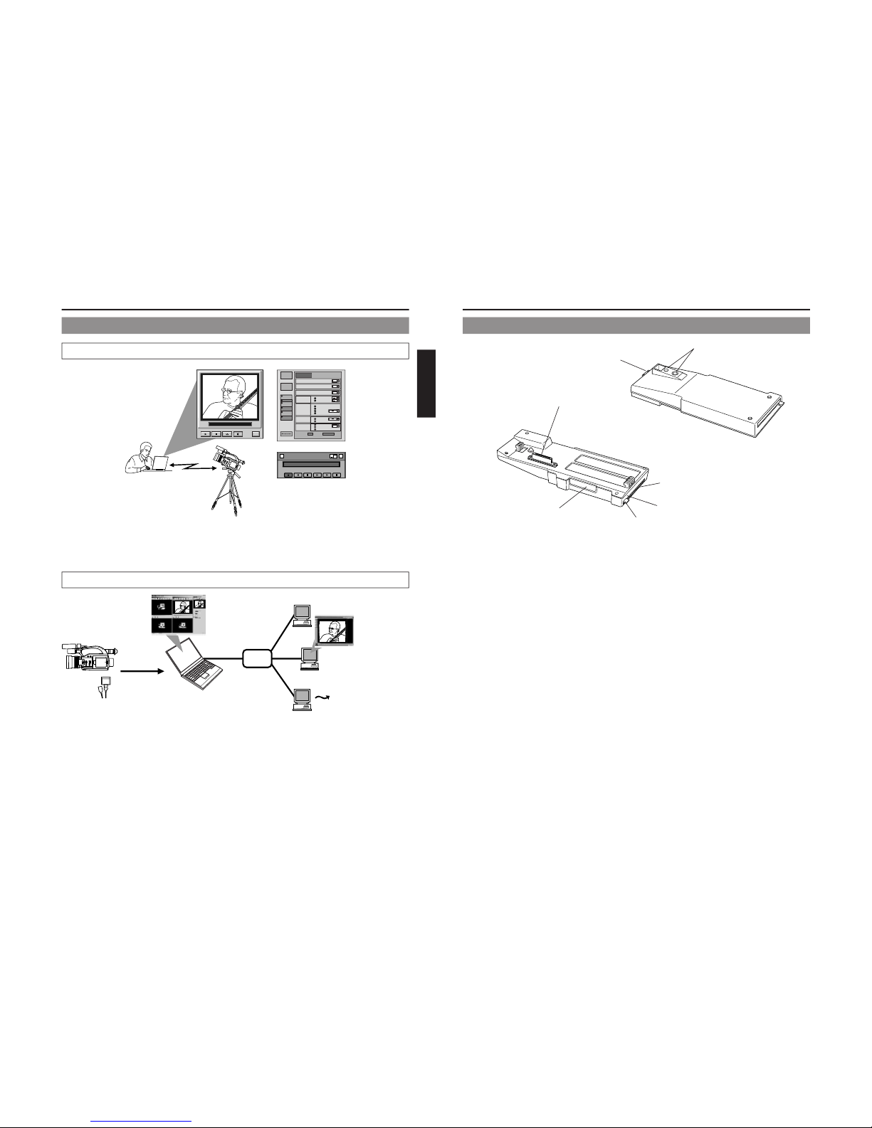
When attaching Network Pack KA-DV300 to DV Camcorder GY-DV300, network related menus are added to the GY-DV300 menu
screen.
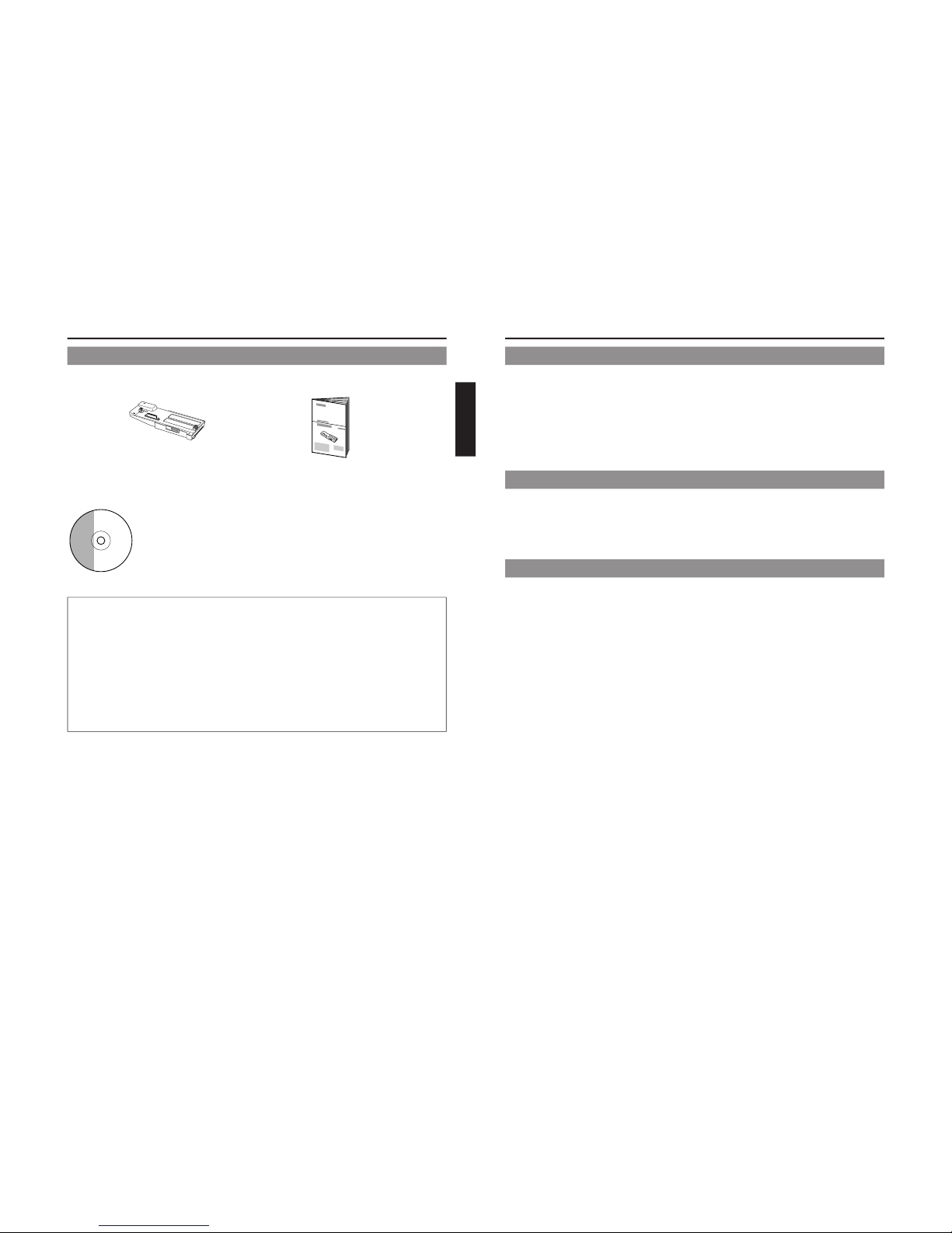
This User’s Guide explains settings for the network related menus, operation for recording streaming data to a CF (Compact Flash)
memory card and operation for sending streaming data using a LAN card. When a LAN card is connected, menu screen settings for the
Network Pack and GY-DV300 can be operated from your PC.
Contents
Introduction
Inserting/removing CF memory card/LAN card ............................................................................................................................... 3
LCD screen/viewfinder screen ......................................................................................................................................................... 4
Menu screen
Menu screen structure ..................................................................................................................................................................... 5
NETWORK PACK CONFIG menu screen items ............................................................................................................................... 6
Setting the NETWORK PACK CONFIG menu screen....................................................................................................................... 8
Returning the NETWORK PACK CONFIG menu screen to factory settings .................................................................................... 9
Network settings
Setting the NETWORK SET menu screen ...................................................................................................................................... 10
NETWORK SET menu screen items ............................................................................................................................................... 11
Making network related settings .................................................................................................................................................... 12
Detailed IP settings (LAN) .............................................................................................................................................................. 13
Detailed network settings (WLAN) ................................................................................................................................................. 14
Recording on a CF card
Formatting a CF memory card ....................................................................................................................................................... 16
CF memory recording time............................................................................................................................................................. 16
Recording video on a DV cassette tape and CF memory card ..................................................................................................... 17
Recording video on a CF memory card only ................................................................................................................................. 18
Recording playback signals of a DV cassette tape on a CD memory card .................................................................................. 19
Deleting all clip files on a CF memory card ................................................................................................................................... 20
Movie clips
Playing back video/audio recorded on a CF memory card ........................................................................................................... 21
Protecting a clip file on a CF memory card .................................................................................................................................... 23
Deleting a clip file on a CF memory card ....................................................................................................................................... 24
Playing back CF memory card clips on your PC ........................................................................................................................... 25
LAN card
Sending video using LAN card while recording on a DV cassette tape ........................................................................................ 26
Sending video using a LAN card (no DV cassette tape recording) ............................................................................................... 27
Sending playback signals of a DV cassette tape using a LAN card ............................................................................................. 28
NETWORK PACK SETUP
Controlling GY-DV300/KA-DV300 via LAN card ............................................................................................................................. 29
CAMERA CONTROL screen .......................................................................................................................................................... 30
NETWORK SETUP screen .............................................................................................................................................................. 31
PORT SETUP screen ...................................................................................................................................................................... 32
ENCODE PARAMETERS screen .................................................................................................................................................... 33
VTR CONTROL screen ................................................................................................................................................................... 34
Streamcapture screen (Playing back video/audio using a PC and saving to file) ......................................................................... 35
Others
Trouble shooting ............................................................................................................................................................................. 37
Checking communication/connection ............................................................................................................................................ 39
Terminology .................................................................................................................................................................................... 40
* In general, the names of products manufactured by other companies and mentioned in these
instructions are trademarks or registered trademarks of these companies.
Symbols like ™, ©, ®, etc., are not used in these instructions.
Caution Cautionary notes concerning operation of the unit
Memo Reference such as restrictions of features, etc.
☞Reference page or item
Characters and symbols used in this instruction book
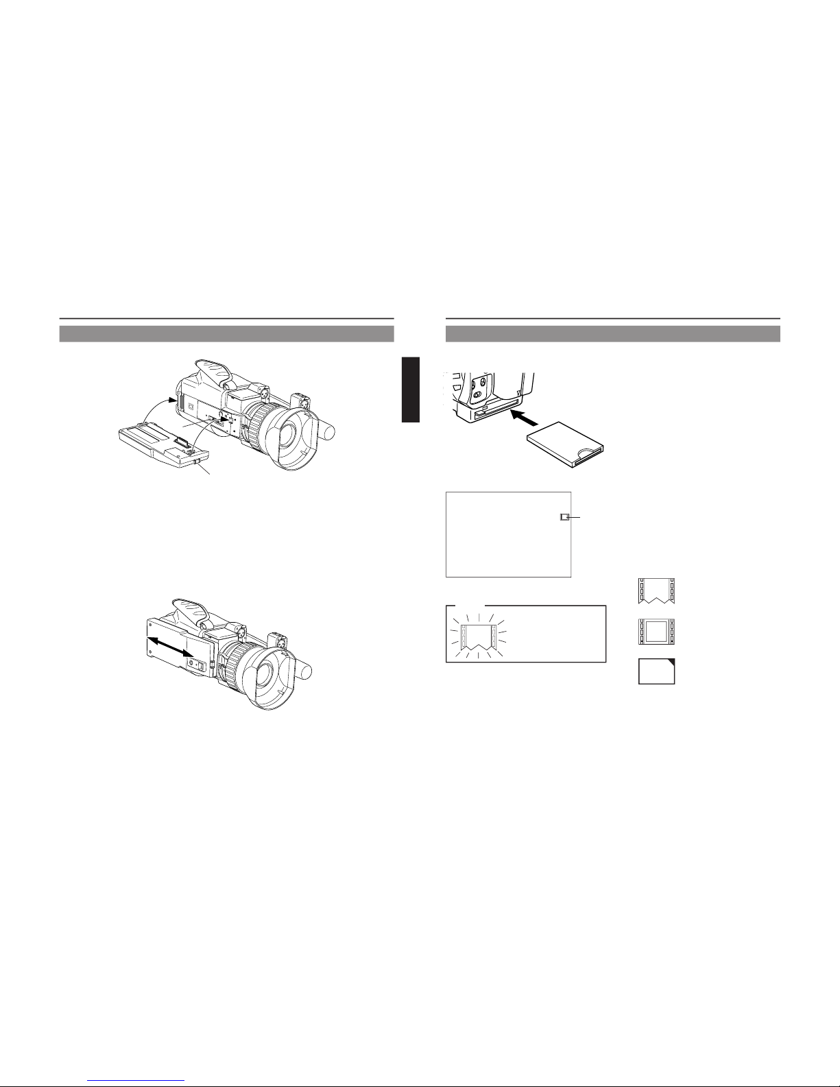
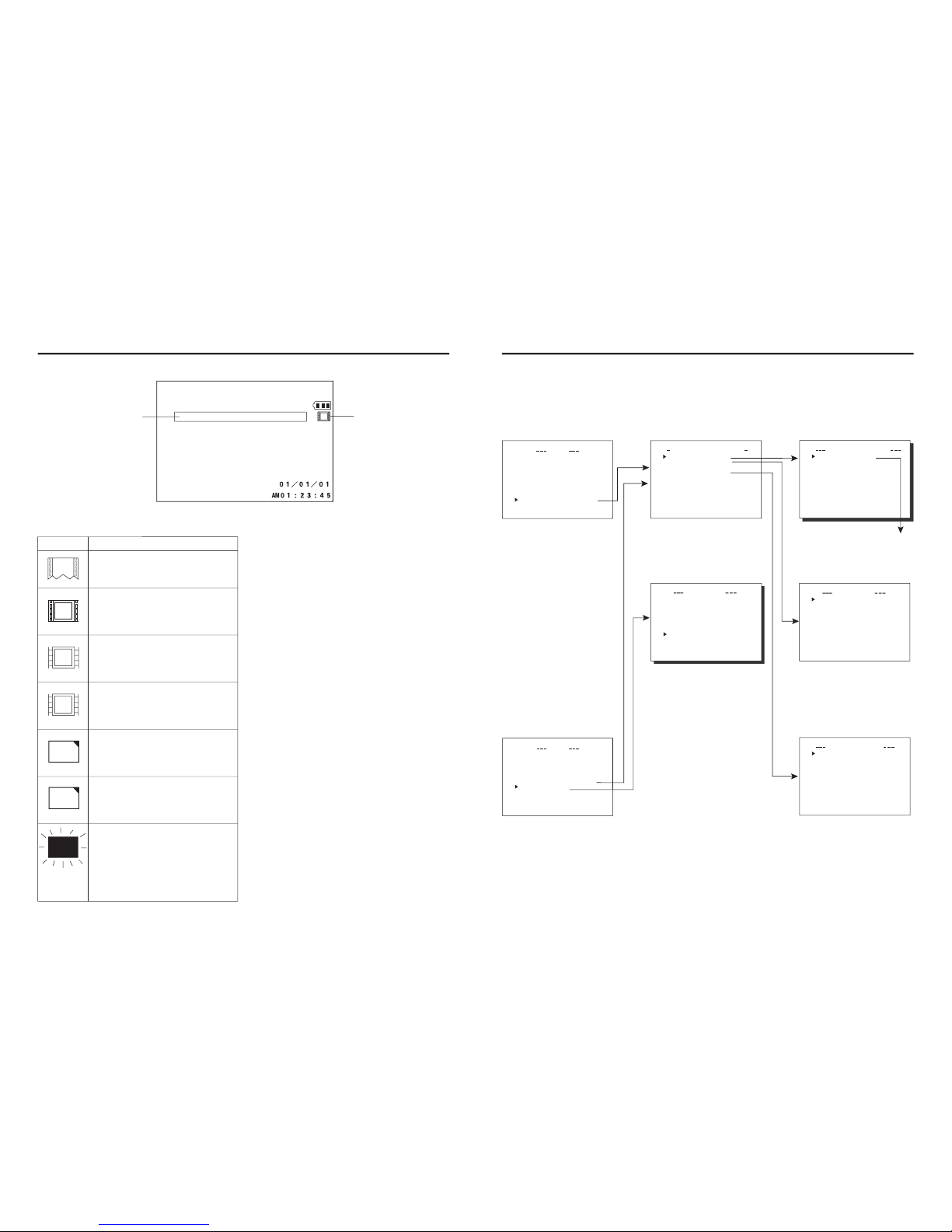
Card status display
: No card
: LAN card
: CF memory card
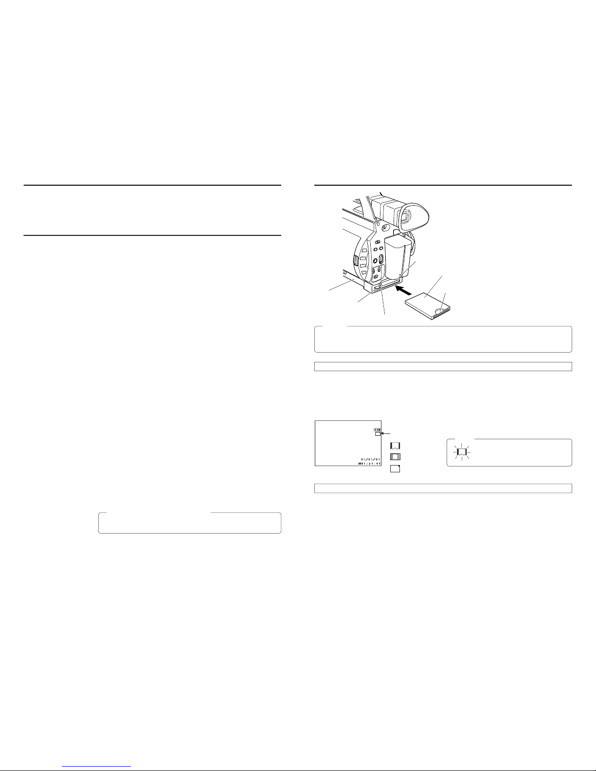
Inserting card
1.
Turn off the GY-DV300 power.
2.
Insert a card into the KA-DV300 card slot.
3.
Turn on the GY-DV300 power.
●Card status according to the inserted card type is displayed on
the LCD screen/viewfinder screen. (☞page 4)
Memo
When turning the power on, the card status
display shown on left will flash during initial-
ization.
Removing card
\Check to make sure the ACCESS lamp of KA-DV300 is off.
The ACCESS lamp will light when the card is in operation.
1.
Turn off the GY-DV300 power.
2.
Press the EJECT button of KA-DV300 and remove the card.
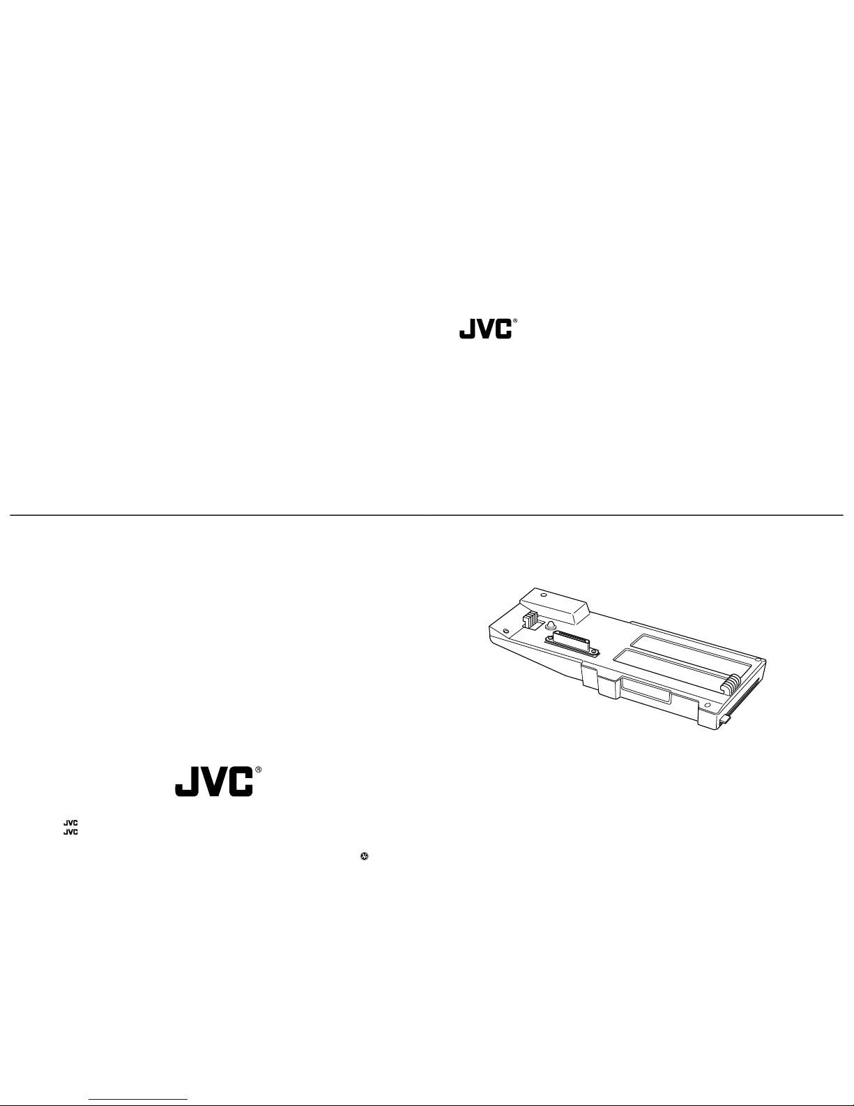
Introduction Inserting/removing CF memory card/LAN card
CF Card adapter/LAN card
●The KA-DV300 accepts the following cards for which operation has been confirmed:
Operating voltage 3.3 V
Current consumption Max. 300 mA
•Wired LAN-card
US: EA2900-117 (Revision C) (Name of manufacturer: Socket Communications,
Inc)
*1
Europe:EA2903-162 (Revision C) (Name of manufacturer: Socket Communications,
Inc)
*1
Asia: EA2906-194 (Revision C) (Name of manufacturer: Socket Communications,
Inc)
*1
* Revision indicated on the upper right of package production label.
•Wireless LAN-card
TEW-PC16 (firmware version 0.8.3 or later) (Name of manufacturer: TRENDware)
WCF11 (Name of manufacturer: LINKSYS)
*2
•CF (Compact Flash) card
SDCFB-16-801 ~ SDCFB-256-801 (Name of manufacturer: SunDisk)
*1
*1: Use PCMCIA card TYPE 1or TYPE 2adapter
*2: Use PCMCIA card TYPE 2adapter