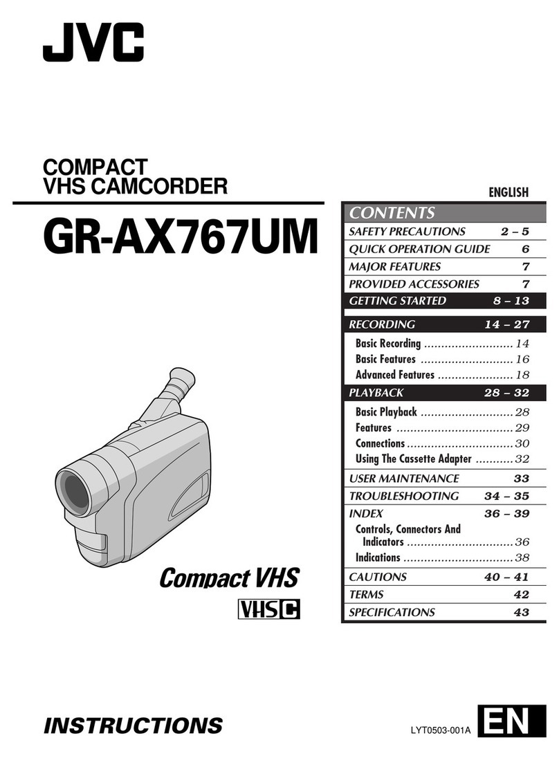
JVC TK-1280E User manual

TK-1280E/-N180E/-1281EG
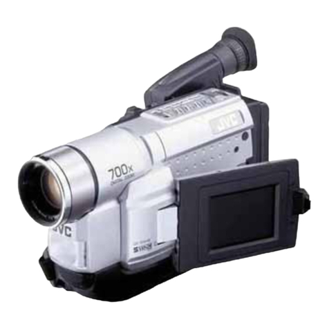
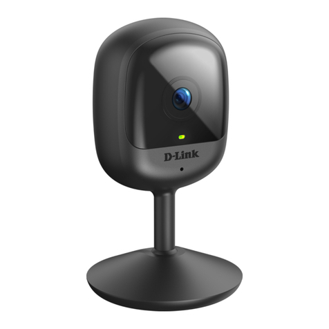
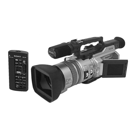
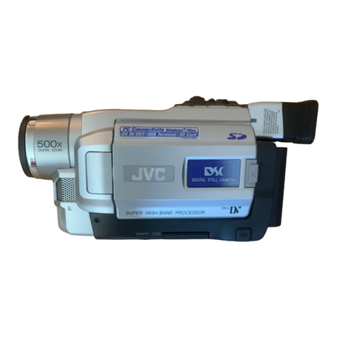
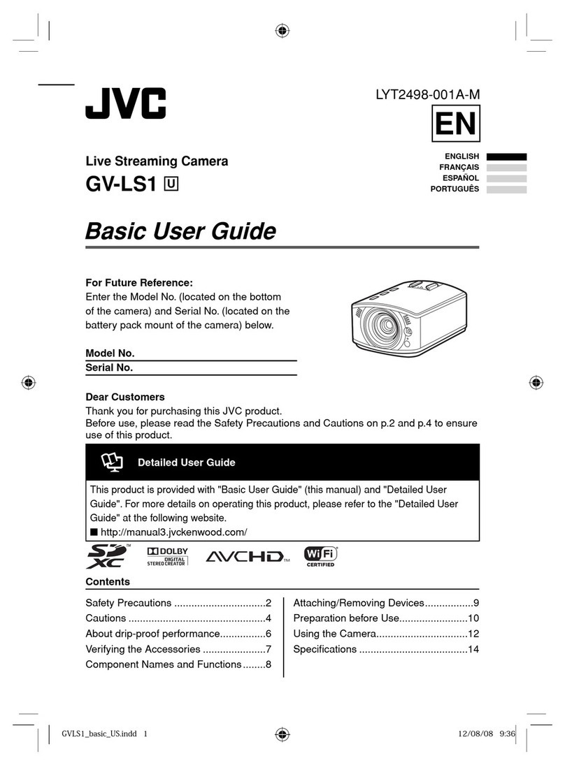
This
illustration
is
Model
TK-1280.
NOTE:
This
service
manual
is
for
TK-1280E
assembled
in
Hachioji
factory.
For
the
unit
assembled
in
lwai
factory,
see
service
manual
number
50716.
The
serial
numbers
from
09852451
and
after
Hachioji
from
10710001
to
09852450
__—si[wai
COPYRIGHT
©
1993
VICTOR
COMPANY
OF
JAPAN,LTD.
No.
6647
June
1993

TK-1280E/-1180E/-1281EG
|
TABLE
OF
CONTENTS
Page
INSTRUCTIONS
MAIN:
PARTS:
GOCATION
ccs
ssccfeccecuctct
cbeadents
debscuterebeeitaceaceestscevies
datadue
seeds
suede
stbueeesuedetunst
value
ygles
lodetedd
eaves
Puen
idiorhces
teu
detgededs
1
SPECIFIC:
SERVICE
INSTRUCTIONS
s:scssesescctsteduieesdecisdedevercsectidistesMaviz
iaeneod
deeshloitstetrat
teach
Roa
euieatvtite
Jaret
aac
its
2
SERVICE-ADSUSTMENT,
cctescea
jac2ensucevesecsassesteneteucessiedags
cactescasSeveshit
gus
cubahcveéd
apitet
sade
diususbbactadoshewsesastde
cex.deceae
Sede
Bestubcasseasiands
8
STANDARD
CIRCUIT
DIAGRAMS
AND
BOARDS
.......cescccesescscesscessesseeseessesessenssesaeseceescssssesescsenenscsesesecsenecsaescaeaeseseneessas
23
REPACKING
vive:
cecccatteesdaassstens
cobs
rec
tiieans
Bekcodaendetc
duced
Wea
tenn
eres
eb
aolsdaldes
desteatatebla
atta
dhdenaclgiedaniae
ail
udiameaedleesrs
46
EXPE
ODED:
VIEVS
sixes
oN
cet
Oe
ita
taal
Seta
nas
he
eS
aah
anh
Ee
ee
cle
ES
ge
Cts
tld
tinal
47
PARTS
EIST:
ctocccscetes
tous
tesscvbacecbeats
ccaeyoeehovsansnhapta
cbenbendsvaesd
eapbede
dutedeatetecacnavenesee
bait
ani
deanevensd
ounatavusand
aavanstaed
ina
watetenseeeiahedss
50

INSTRUCTIONS
A
pn
Giatsie]
COLOUR
VIDEO
CAMERA
HEAD
BEDIENUNGSANLEITUNG:
FARB-VIDEOKAMERAKOPF
MANUEL
DINSTRUCTIONS:
TETE
DE
CAMERA
VIDEO
COULEUR
TK-1280E
instructions
see
the
TK-1280E
service
manual
No.
50716.
INSTRUCTIONS
TK-1281EG
COLOUR
VIDEO
CAMERA
BEDIENUNGSANLEITUNG:
FARB-VIDEOKAMERA
MANUEL
D
INSTRUCTIONS:
CAMERA
VIDEO
COULEUR

WARNING:
TO
PREVENT
FIRE
OR
SHOCK
HAZARD,
DO
NOT
EXPOSE
THIS
APPLIANCE
TO
RAIN
OR
MOISTURE.
CAUTION:
To
prevent
electric
shock,
do
not
open
the
unit.
No
user
serviceable
parts
inside.
Refer
servicing
to
qualified
service
personnel.
CAUTION:
To
prevent
electric
shocks
and
risk
of
fire
hazards,
do
NOT
use
other
than
the
specified
power
source.
This
installation
should
be
made
by
a
qualified
ser-
vice
person
and
should
conform
to
all
local
codes.
WARNING:
TO
PREVENT
FIRE
OR
SHOCK
HAZARD,
DO
NOT
EXPOSE
THIS
APPLIANCE
TO
RAIN
OR
MOISTURE.
WARNING-THIS
APPLIANCE
MUST
BE
EARTHED
IMPORTANT
The
wires
in
this
mains
lead
are
coloured
in
accordance
with
the
following
code:
GREEN-AND-YELLOW:
EARTH
BLUE:
NEUTRAL
BROWN:
LIVE
As
the
colours
of
the
wires
in
the
mains
lead
of
this
apparatus
may
net
correspond
with
the
coloured
markings
identifying
the
termi-
nals
in
your
plug,
proceed
as
follows.
The
wire
which
is
coloured
GREEN-AND-YELLOW
must
be
connected
to
the
terminal
in
the
plug
which
is
marked
with
the
letter
E
or
by
the
safety
earth
symbol!
+
or
coloured
GREEN
or
GREEN-AND-YELLOW.
The
wire
which
is
coloured
BLUE
must
be
connected
to
the
terminal
which
is
marked
with
the
letter
N
or
coloured
BLACK.
The
wire
which
is
coloured
BROWN
must
be
connected
to
the
terminal
which
is
marked
with
the
letter
L
or
coloured
RED.
Thank
you
for
purchasing
a
JVC
colour
video
camera
head.
To
obtain
the
best
results
from your
new
camera,
read
this
instruction
manual
carefully
before
use;
retain
the
manual
for
future
reference.
This
instruction
manual
is
divided
into
three
sections:English,
German,
French.
Te
Co)
Ne
RSE
nee
a
ROE
Page
2-23
German
...
...
Page
24
~
45
FONGHY
occcdoseseectadeectecatirodeeichtneieteusiteieta
sive
Page
46
-
67
FOGUINOS
asf
ossee
du
cesessa
Gade
acide
gucsavauhavest
cas
eecsesenasaseeansundseettacrstnds
3
Precautions
(USC)
0.0...
eseseceeeereseeeeeesesasereeeaesereeseesensseeegs
3
Controls
and
their
locations
.0........ccseesesscesresteesteseceeeseeenseeenes
4
Installation
(IEMS)
oo.
eee
esses
seeenececrseeecesenseseaeeeeeroeteneenes
14
Mounting
a
IEns
200...
ee
cee
ecsseeeeeeereeeeneesseeseaeesnenennereeees
15
Adjusting
auto-iris
IEMS@S
0...
ees
ceeeeeecteeteeeteeeneeeeeenes
15
Flange-back
adjUStMent
0...
eee
eescceereeeeeeeeeecreeeeasenseees
16
Lens
that
can
be
USE”
ooo...
eee
cr
secre
ctere
ee
ceeatereneneeeenee
17
Connection
examples
.......cccccccccsssessscesssesesesescceseeetseeeeeeeeenees
18
Installation
(camera)
...
20
Installation
oo...
eee
sense
eens
..20
Tripod
mounting
base
movement
...
20
Precaution
(installation)
..............cce
21
Specifications:
i.
vcelesssc..,
cists
destivetestGecectenteeeetedevnseuacanoviessens
22
Thank
you
for
purchasing
a
JVC
colour
video
camera.
To.obtain
the
best
results
from
your
new
camera,
read
this
instruction
manual
carefully
before
use;
retain
the
manual
for
future
reference.
This
instruction
manual
is
divided
into
three
sections:
English,
German,
French.
CONTENTS
FEATURES.
........ccsssscnceescceseseccesstecnnsesecscanasseeeneeeenereee
PRECAUTIONS
(USE)
CONTROLS
AND
THEIR
LOCATIONS
INSTALLATION
(LENS)............:e0secceeeeeseeseeeeeees
ioe
Mounting
2
lens
............
cece
ee
cence
eeeee
eaten
eeenaeennee
Adjusting
auto-iris
lenses
................ccccceeeeeeeeeeneeee
renee
Flange-back
adjustment
....
Lens
that
can
be
used
.......
CONNECTION
EXAMPLES
....
INSTALLATION
(CAMERA)
....
Installation
2.0.0...
eeceececese
esac
neeeeeeeeeees
Tripod
mounting
base
movement
PRECAUTION
(INSTALLATION)...............
SPECIFICATIONS
..0..........
ee
ceeceecercnseececseeeenenseeeeeeeraeans
FEATURES
CCD
IRIS
function
to
automatically
set
the
brightness
of
the
picture
by
changing
the
shutter
speed
of
the
camera
accord-
ing
to
the
light
incident
when
using
a
manual
iris
Jens.
AGC
(Automatic
Gain
Control)
function
to
automatically
increase
camera's
sensitivity
when
the
level
of
ambient
light
drops.
Built-in
back-light
compensation
function
Either
the
galvanometric
auto-iris
lens
or
the
video-level-
sensing
auto-iris
lens
can
be
used.
TTL
(Through-The-Lens)
auto
tracking
white
balance
adjust-
ment
with
preset
luminous
intensity
(03
and
manual
override
(2
axes;
G-Mg
and
R-B)
Changeable
C/CS
lens
mount
allows
selection
from
a
wide
range
of
lenses.
Gen-lock
and
line-lock
functions
are
provided.
Built-in
electronic
shutter
to
allow
switching
to
9
shutter
speeds.
Convenient
external
flange-back
adjustment
function
allows
adjustment
using
a
screwdriver.
Compact,
light-weight
design
greatly
reduces
the
space
required
for
installation.
AC
or
DC
operation.
FEATURES
Automatic
Electronic
Shutter
function
to
automatically
set
the
brightness
of
the
picture
by
changing
the
shutter
speed
of
the
camera
according
to
the
fight
incident
when
using
a
manual
iris
lens.
AGC
(Automatic
Gain
Control)
function
to
automatically
increase
camera’s
sensitivity
when
the
level
of
ambient
light
drops.
Built-in
back-light
compensation
function
Either
the
galvanometric
auto-iris
lens
or
the
video-level-
sensing
auto-iris
lens
can
be
used.
TTL
(Through-The-Lens)
auto
tracking
white
balance
adjust-
ment
with
preset
luminous
intensity
4)
and
manual
override
(2
axes;
G-Mg
and
R-B)
Changeable
C/CS
lens
mount
allows
selection
from
a
wide
range
of
ienses.
Gen-lock
and
line-lock
functions
are
provided.
Built-in
electronic
shutter
to
allow
switching
to
9
shutter
speeds.
Convenient
external
flange-back
adjustment
function
allows
adjustment
using
a
screwdriver.
Separated
Y/C
video
signal
output
connector.
220
—
240
V
AC
operation.
PRECAUTIONS
use)
When
operation
is
incorrect
or
a
malfunction
is
observed:
While
operation,
if
any
abnormal
condition
(strange
sound,
smell
or
smoke)
or
a
malfunction
(no
picture,
etc.)
is
observed,
stop
using
the
camera
immediately,
turn
the
power
off,
then
call
your
local
deater.
Cleaning
Turn
the
power
off
and
wipe
off
the
dirt
with
a
dry
soft
cloth.
If
it
is
extremely
dirty,
use
furniture
cleaner
to
wipe
it
off.
To
clean
the
lens,
use
a
blower
of
lens
cleaning
tissue
(avail-
able
from
any
camera
dealer).
e
Do
not
point
the
camera
at
the
sun.
This
could
damage
the
camera
whether
it
is
operating
or
not.
Do
not
shoot
any
source
of
bright
light.
{f
the
object
con-
tains
very
bright
areas,
bright
vertical
or
horizontal
lines
may
appear
on
the
screen.
This
is
called
“smear”,
a
phenomenon
which
often
occurs
with
solid-state
pickups,
and
is
not
a
mal-
function.
Do
not
disassemble
the
camera
and
never
touch
parts
in-
side
the
camera
as
you
could
damage
the
camera.
Do
not
allow
anything
to
get
inside
the
camera.
If
a
metal
or
flammable
object
gets
inside
the
camera,
it
may
cause
a
malfunction.
Handle
with
care.
Do
not
drop
the
camera
or
subject
it
to
shocks
and
vibrations
to
avoid
possible
damage.
“Also
read
“Precautions
(installation)”
on
page
21
carefully.
PRECAUTIONS
use)
When
operation
is
incorrect
or
a
malfunction
is
observed:
While
operation,
if
any
abnormal
condition
(strange
sound,
smeil
or
smoke)
or
a
malfunction
(no
picture,
etc.)
is
observed,
stop
using
the
camera
immediately,
turn
the
power
off,
then
call
your
jocal
dealer.
Cleaning
Turn
the
power
off
and
wipe
off
the
dirt
with
a
dry
soft
cloth.
If
it
is
extremely
dirty,
use
fumiture
cleaner
to
wipe
it
off.
To
clean
the
lens,
use
a
blower
of
lens
cleaning
tissue
(avail-
abie
from
any
camera
dealer).
Do
not
point
the
camera
at
the
sun.
This
could
damage
the
camera
whether
it
is
operating
or
not.
Do
not
shoot
any
source
of
bright
light.
If
the
object
con-
tains
very
bright
areas,
bright
vertical
or
horizontal
lines
may
appear
on
the
screen.
This
is
called
“smear”,
a
phenomenon
which
often
occurs
with
solid-state
pickups,
and
is
not
a
mal-
function.
Do
not
disassemble
the
camera
and
never
touch
parts
in-
side
the
camera
as
you
could
damage
the
camera.
Do
not
allow
anything
to
get
inside
the
camera.
If
a
metal
or
flammable
object
gets
inside
the
camera,
it
may
cause
a
malfunction.
Handle
with
care.
Do
not
drop
the
camera
or
subject
it
fo
shocks
and
vibrations
to
avoid
possible
damage.
“Also
read
“PRECAUTIONS
(INSTALLATION)”
on
page
20
carefully.
3

CONTROLS
AND
THEIR
LOCATIONS
Side
view
Front
view
CONTROLS
AND
THEIR
LOCATIONS
Side
view
Front
view

Lens
mount
cap
Be
sure
to
cap
the
lens
mount
when
the
fens
is
not
mount-
ed.
Turn
counterclockwise
to
remove.
C-mount
adapter
To
mount
a
C-mount
lens
a
C-mount
adapter
is
provided.
To
mount
a
CS-mount
lens,
remove
the
C-mount
adapter.
Any
lens
for
1/3”,
1/2”,
2/3”
or
1”
video
camera
can
be
used.
Turn
clockwise
to
remove
it.
Also
refer
to
page
15.
Ei
FOCUS
screw
A
screw
is
provided
to
adjust
and
fix
the
flange-back
(the
distance
from
the
lens
mounting
to
the
focal
point).
See
page
16.
£4
Tripod
mounting
base
This
is
the
mounting
base
for
installing
the
camera.
See
page
14
and
20.
EJ
VIDEO
OUT
connector
BNC
connector
that
outputs
a
composite
video
signal.
Connect
to
the
video
input
connector
of
a
monitor,
switcher,
etc.
e@
Use
a
coaxial
cable
for
connection.
Lens
mount
cap
Be
sure
to
cap
the
lens
mount
when
the
lens
is
not
mount-
ed.
Turn
counterclockwise
to
remove.
C-mount
adapter
A
C-mount
adapter
is
provided
to
mount
a
C-mount
lens.
When
mount
a
CS-mount
lens,
remove
the
C-mount
adapter
at
first.
Any
lens
for
1/2”,
2/3”
or
1”
video
camera
can
be
used.
Then,
turn
clockwise
it.
Also
refer
to
page
14.
FOCUS
screw
A
screw
is
provided
to
adjust
and
fix
the
flange-back
(the
distance
from
the
lens
mounting
to
the
focal
point).
See
page
15.
E3
Tripod
mounting
base
This
is
the
mounting
base
for
installing
the
camera.
See
page
13
and
19.
VIDEO
OUT
connector
BNC
connector
that
outputs
a
composite
video
signal.
Connect
to
the
video
input
connector
of
a
monitor,
switcher,
ete.
e
Use
a
coaxial
cable
for
connection.
{@
Y/c
OUT
connector
Output
connector
for
separated
Y/C
video
signals.
Connect
to
the
S-VIDEO
input
connector
of
a
video
monitor,
etc.
If
the
plug
on
the
cable
is
of
a
different
type,
replace
it
with
the
provided
4-pin
plug.
Pin
assignment:
Y/C
OUT
connector
(4-pin)
|
PinNo.|
Signal
GND
Y/C
OUT
GND
Y
(Luminance,
1
Vp-p,
75
ohms)
C
(Chrominance,
0.3
Vp-p
(burst),
75
ohms)

J
SYNC
IN
connector
@
BNC
connector
for
external
sync
reference
signal
input
such
as
composite
video
signa!
(VBS)
or
black
burst
sig-
Notes:
e
{f
the
external
sync
signal
to
be
input
is
less
than
—4dB
with
respect
to
the
reference
level,
sync
operation
is
not
RalEB).
ssible
e
Connect
to
the
connector
outputting
the
signal
to
be
po
.
used
as
a
reference
for
extemal
sync.
Reference
level
|Composite
video
signal
|
1.0
Vp-p*
e
Use
a
coaxial
cable
for
connection.
(VBS)
e@
When
the
sync
reference
signal
is
input,
the
camera
automatically
switches
from
the
internal
to
external
sync
Black
burst
signal
(BB)
j
0.45
Vp-
mode
to
parton
ger:loer
operation,
*
The
video
components
of
the
signal
do
not
matter.
Caution:
e
Before
performing
gen-lock
operation
with
the
external
sync
signal
input,
make
sure
to
set
the
sync
mode
switch
to
“VE”
position.
(See
page
12.)
e@
When
an
external
H/V
sync
signal
is
input,
the
camera
automatically
switches
to
H/V
lock
mode
when
the
sync
mode
switch
is
set
in
LL
position.
(See
page
12.)
e
Gen-lock
operation
may
become
unstable
using
a
sig-
nal
containing
severe
jitter
(vertical
or
horizontal
picture
vibrations)
such
as
a
video
recorder
playback
signal.
e
When
gen-iock
operation
is
performed,
adjustment
of
horizontal
phase
and
colour
sub-carrier
phase
are
required.
(See
page
13.)
Connections
for
line-lock
operation
Connection
Example
e
Set
the
sync
mode
switch
to
LL
position.
(See
page
12.)
one
Out
os
7
Switcher
e@
When
performing
line-lock
operation,
the
V
phase
ad-
Qe
Se
;
justment
is
required.
(See
page
13.)
:
eu
‘ower
Source:
ue
Cautio
AC220-240V,
SOHz
AC24V,
50
Hz
n:
e@
Do
not
input
the
external
sync
signal
to
the
SYNC
IN
con-
ee
From
VIDEO
OUT
—»
nector.
CAL}
Power
Source:
Power
Source
was
AC24V.
50H2
AC
220-240V,
50
Hz
SYNC
IN
connector
sisages
e@
BNC
connector
for
external
sync
reference
signal
input
@
If
the
external
sync
signal
to
be
input
is
less
than
—4dB
Such
as
composite
video
signal
(VBS)
or
black
burst
sig-
with
respect
to
the
reference
tevel,
sync
operation
is
not
nal
(BB).
:
possible.
Reference
level
|Composite
video
signal
1.0
Vp-p’
(VBS)
e@
Connect
to
the
connector
outputting
the
signal
to
be
used
as
a
reference
for
external
sync.
e@
Use
a
coaxial
cable
for
connection.
@
When
the
sync
reference
signal
is
input,
the
camera
:
automatically
switches
from
the
intemal
to
external
sync
0.45
Vp-p
mode
to
perform
gen-lock
operation.
*
The
video
components
of
the
signal
do
not
matter.
Caution:
e@
Before
performing
gen-iock
operation
with
the
external
sync
signal
input,
make
sure
to
set
the
sync
mode
switch
to
“VE”
position.
(See
page
11.)
@
When
an
external
H/V
sync
signal
is
input,
the
camera
automatically
switches
to
H/V
lock
mode
when
the
sync
mode
switch
is
set
in
LL
position.
(See
page
11.)
e@
Gen-lock
operation
may
become
unstable
using
a
sig-
nal
containing
severe
jitter
(vertical
or
horizontal
picture
vibrations)
such
as
a
video
recorder
playback
signal.
@
When
gen-lock
operation
is
performed,
adjustment
of
horizontal
phase
and
colour
sub-carrier
phase
are
required.
(See
page
12.)
Connections
for
line-lock
operation
e
Set
the
sync
mode
switch
to
LL
position.
(See
page
11.)
@
When
performing
line-iock
operation,
the
V
phase
ad-
o_O
justment
is
required.
(See
page
12.)
Power
Source:
220-240
V
AC,
50/60
Hz
Caution:
t
VIDEO
@
Do
not
input
the
external
sync
signal
to
the
SYNC
IN
con-
se
From
VIDEO
OUT
—>
Power
Source:
=
220
-
240
V
AC,
50/60
Hz
ae

VIDEO
IRIS
connector
Connect
the
iris
cable
of
an
video-level-sensing
auto-iris
lens.
if
the
plug
on
the
cable
is
of
a
different
type,
replace
it
with
the
provided
3-pin
iris
plug.
Note:
e
Use
video-level-sensing
auto-iris
lens
using
DC
9V
-
10V
with
power
consumption
of
50
mA
or
fess.
Pin
assignment:
VIDEO
IRIS
connector
(3-pin)
[PinNo.|
__Signal__
Co
a
vi
ie
oes
feed
Video
(0.7
Vp-p
high
impedance,
no
sync
@)-
TE
EJ
VIDEO
IRIS
connector
Connect
the
iris
cable
of
an
video-level-sensing
auto-iris
lens.
If
the
plug
on
the
cable
is
of
a
different
type,
replace
it
with
the
provided
3-pin
iris
plug.
Note:
e
Use
video-level-sensing
auto-iris
lens
using
DC
9
V
—
10
V
with
power
consumption
of
50
mA
or
less.
Pin
assignment:
VIDEO
IRIS
connector
(3-pin)
VIDEO
3
IRIS
NY
DC
9V-10V
(50
mA
max.)
aN
be
Video
(0.7
Vp-p
high
impedance,
no
sync
E]
DC
IRIS
connector
Connect
the
iris
cable
of
the
galvanometric
auto-iris
lens.
If
the
plug
on
the
cable
is
of
a
different
type,
replace
it
with
the
provided
4-pin
iris
plug.
Pin
assignment:
DC
IRIS
connector
(4-pin)
2
1
DC
IRIS
|
1.‘
Control
-
aoc
Controt
+
|
3
|
Drive(+)
Drive
(-
E]
DC
IRIS
connector
Connect
the
iris
cable
of
the
galvanometric
auto-iris
lens.
If
the
plug
on
the
cable
is
of
a
different
type,
replace
it
with
the
provided
4-pin plug.
Pin
assignment:
DC
IRIS
connector
(4-pin)
2
1
pe
IRIS
os
ee
|
2
|
Control(+)
|
|
3
|
4
|
Power
cord
Supply
power
from
an
AC
outlet
(220
to
240
V).
Caution:
¢
Be
sure
not
to
connect
the
power
source
until
all
other
connections
are
complete.
Do
not
turn
the
power
of
any
equipment
on
until
connections
are
completed.
POWER
indicator
Lights
when
the
camera
is
powered.

E]
Power
input
terminal
(12V==
/24
V~)
Connect
to
a
DC
12
V
or
AC
24
V
power
source.
When
DC
Caution:
12
V
power
is
to
be
supplied
from
an
AC
220
V
to
240
V
@
Be
sure
not
to
connect
the
power
source
until
all
other
connections
are
complete.
Do
not
turn
the
power
of
any
equipment
on
until
connections
are
completed.
The
power
voltage
is
specified
as
DC
12
V
or
AC
24
V.
Be
careful
to
connect
the
DC
12
V
power
supply,
with
power
source,
use
the
optional
AC
adapter
AC-C624
(for
the
U.K.)
or
AC-C622
(for
countries
other
than
the
U.K.).
When
operating
with
an
AC
24
V
power
supply,
use
only
an
isolated
power
source.
:
the
correct
+/—
polarity.
Use
a
DC
12V
power
source
with
ripple
voltage
of
less
than
50
mV.
Do
not
power
the
unit
with
both
AC
24
V
and
DC
12
V
at
the
same
time.
Be
sure
to
connect
only
one
power
source.
CEE
OC
12v
-
Power
source
POWER
indicator
Lights
when
the
camera
is
powered.
Saee
Picture
adjustment
section
AGC,
BLC,
Shutter
mode,
IRIS
LEVEL,
Sync
mode,
H/V
phase,
SC
phase
and
White
balance
controls
are
provided.
Perform
the
following
adjustments
and
settings
according
to
the
shooting
(or
lighting)
conditions.
|

Picture
adjustment
section
AGC,
BLC,
shutter
speed,
IRIS
LEVEL,
sync
mode,
H/V
phase,
SC
phase
and
white
balance
controls
are
provided.
Perform
the
following
adjustments
and
settings
according
to
the
shooting
(or
lighting)
conditions.
|
00
es
AUTOR
(1000
let
L120
@Q
White
balance
adjustment
switch
This
is
used
for
changing
the
setting
of
the
white
balance.
MANU:
Manual
adjustment
is
possible.
ATW:
Accepts
different
types
of
lighting
(colour
temper-
atures
ranging
from
approx.
2850
K
to
7000
K)
using
an
automatic
tracing
system.
(TK-1281EG
uses
a
TTL
system
that
measures
light
entering
the
camera
lens.)
#«
:
For
shooting
under
the
artificial
light
such
as
halo-
gen
lamps
(colour
temperature
approx.
3200
K).
Notes:
@
When
using
the
camera
under
a
fluorescence
light
with
high
shutter
speed,
the
white
balance
may
change
peri-
odically.
The
automatic
tracing
system
may
not
function
proper-
ly
when
shooting
with
non-standard
lighting
or
lighting
with
a
colour
temperature
that
exceeds
the
range
of
the
camera.
Because
it
uses
a
TTL
system,
if
a
coloured
object
is
shot
(especially
one
with
a
single
colour)
that
fills
most
of
the
camera’s
field
of
view,
the
colour
tem-
perature
may
be
judged
incorrectly
and
the
correct
white
baiance
adjustment
may
not
be
possible.
In
such
a
case,
set
to
the
“MANU”
position.
@
White
balance
adjustment
controls
When
the
white
balance
adjustment
switch
is
set
to
“MANU”,
the
white
balance
can
be
adjusted
manually.
G-Mg:
Tur
to
the
“G”
side
to
increase
the
amount
of
green
in
the
picture.
Tum
to
the
“Mg”
side
to
increase
the
amount
of
magenta.
B-R:
Turn
to
the
“B”
side
to
increase
the
amount
of
blue.
Turn
to
the
“R”
side
to
increase
the
amount
of
rc.
©
IRIS
LEVEL
contro!
The
brightness
control
of
the
monitor
picture
does
notoper-
ate
correctly,
adjust
using
this
control.
Turn
OFF
the
AGC
switch
(set
to
ON
at
the
factory)
to
adjust
the
IRIS
LEVEL
control.
Monitor
picture
Adjustment
direction
To
make
it
brighter
To
make
it
darker
Turn
counterclockwise.
Notes:
©
This
function
is
activated
when
the
camera
SHUTER
mode
select
switch
is
set
to
AUTO
position
and
wiem
using
the
galvanometric
auto-iris
lens
or
the
vido-
level-sensing
auto-iris
lens.
Be
careful
not
to
turn
the
IRIS
LEVEL
contro!
beynd
its
limits
as
this
could
cause
a
malfunction
in
he
camera's
auto-iris
control.

@
White
balance
adjustment
switch
This
is
used
for
changing
the
setting
of
the
white
balance.
MANU:
Manual!
adjustment
is
possible.
ATW:
Accepts
different
types
of
lighting
(colour
tempera-
tures
ranging
from
approx.
2850
K
to
7000
K)
using
an
automatic
tracing
system.
(TK-1180E
uses
a
TTL
system
that
measures
light
entering
the
camera
lens.)
6:
:
For
shooting
under
the
artificial
fight
such
as
halo-
gen
lamps
(colour
temperature
approx.
3200
K).
Notes:
@
When
using
the
camera
under
a
fluorescence
light
with
high
shutter
speed,
the
white
balance
may
change
peri-
odically.
The
automatic
tracking
system
may
not
function
proper-
ly
when
shooting
with
non-standard
lighting
or
lighting
with
a
colour
temperature
that
exceeds
the
range
of
the
camera.
Because
it
uses
a
TTL
system,
if
a
coloured
object
is
shot
(especially
one
with
a
single
colour)
that
fills
most
of
the
camera’s
field
of
view,
the
colour
tem-
perature
may
be
judged
incorrectly
and
the
correct
white
balance
adjustment
may
not
be
possible.
In
such
a
case,
set
to
the
“MANU”
position.
@
White
balance
adjustment
controls
When
the
white
balance
adjustment
switch
is
set
to
“MANU”,
the
white
balance
can
be
adjusted
manually.
G-Mg;:
Turn
to
the
“G”
side
to
increase
the
amount
of
green
in
the
picture.
Turn
to
the
“Mg”
side
to
increase
the
amount
of
magenta.
B-R:
Turn
to
the
“B”
side
to
increase
the
amount
of
blue.
Turn
to
the
“R”
side
to
increase
the
amount
of
red.
@
IRIS
LEVEL
control
The
brightness
control
of
the
monitor
picture
does
not
oper-
ate
correctly,
adjust
using
this
control.
Turn
OFF
the
AGC
switch
(set
to
ON
at
the
factory)
to
adjust
the
IRIS
LEVEL
control.
Monitor
picture
Adjustment
direction
To
make
it
brighter
To
make
it
darker
Turn
counterclockwise.
Notes:
e
This
function
is
activated
when
the
camera
SHUTTER
mode
select
switch
is
set
to
AUTO
position
and
when
using
the
galvanometric-iris
lens
or
the
video-iris
lens.
@
Be
careful
not
to
turn
the
IRIS
LEVEL
contro!
beyond
its
limits
as
this
could
cause
a
malfunction
in
the
camera's
auto-iris
control.
@
SHUTTER
mode
select
switch
This
varies
the
shutter
speed
(the
time
the
change
is
stored).
Normally,
when
a
fast-moving
object
is
being
shot,
still
or
slow-motion
played
back
pictures
will
be
blurred.
In
this
case,
switching
the
shutter
speed
from
the
normal
speed
of
1/50
second
to
a
faster
speed
allows
each
frame
to
be
recorded
with
greater
detail,
at
the
higher
speed.
When
using
a
manual
iris
lens,
the
brightness
of
the
pic-
ture
image
will
be
fixed
by
setting
this
switch
in
AUTO
(Automatic
electronic
shutter)
position,
as
the
shutter
speed
is
automatically
varied
according
to
the
light
inci-
dent.
Switch
position
Shutter
speed
NORM
GEEE
1/50
second
Normally,
set
to
this
position.
120
ABOU
(Switches
No.
3
and
4
1/120
second
can
be
set
either
in
upper
or
lower
position)
AUTO
FEOO
'
Automatic
electronic
(Switches
No.
3
and
4
shutter
function
can
be
set
either
in
upper
|
(Do
not
set
this
switch
in
this
position
or
lower
position.)
when
using
an
auto-iris
lens.)
10
Caution:
¢
The
automatic
electronic
shutter
function
is
not
acti-
vated
for
a
light
object
to
be
shot,
such
as
in
outdoor
condition.
In
such
a
case,
use
the
camera
with
the
auto-iris
or
manual-iris.
Notes:
e
Faster
shutter
speeds
require
more
light
than
the
nor-
mal
speed.
(In
the
1000
mode,
the
sensitivity
is
approx.
1/20
that
at
normal
speed;
in
the
10000
mode,
approx.
1/200.)
@
When
shooting
with
the
faster
shutter
speed,
or
when
a
light
object
is
being
shot
by
setting
in
AUTO
position
(the
shutter
speed
becomes
faster),
the
brightness
and
white
balance
may
change
periodically.
Shooting
with
artificial
lighting
(especially
fluorescent
lights)
will
cause
the
pictures
to
flicker.
Smear
(bright
horizontal
or
verti-
cal
lines)
which
can
often
be
seen
with
solid-state
pick-
ups
may
appear
in
the
picture.

@
SHUTTER
mode
select
switch
This
varies
the
shutter
speed
(the
time
the
change
is
stored).
Normally,
when
a
fast-moving
object
is
being
shot,
still
or
slow-motion
played
back
pictures
will
be
blurred.
In
this
case,
switching
the
shutter
speed
from
the
normal
speed
of
1/50
second
to
a
faster
speed
allows
each
frame
to
be
recorded
with
greater
detail,
at
the
higher
speed.
When
using
a
manual
iris
lens,
the
brightness
of
the
picture
image
will
be
fixed
by
setting
this
switch
in
AUTO(CCD
iris)
position,
as
the
shutter
speed
is
automatically
varied
according
to
the
light
incident.
Switch
position
Shutter
speed
Reeser
1/50
second
NORM
[2]
[a]
2!
&]
Normally,
set
to
this
position.
120
ABOU
(Switches
No.
3
and
4
1/120
second
can
be
set
either
in
upper
or
lower
position)
125
BOE
1/125
second
1/250
second
1/500
second
1/1000
second
1/2000
second
1/4000
second
AUTO
FAOO
(Switches
No.
3
and
4
can
be
set
either
in
upper
or
lower
position.)
CCD
iris
function
(Do
not
set
this
switch
in
this
position
when
using
an
auto-iris
lens.)
@
BLC
(Back
Light
Compensation)
switch
This
function
makes
the
iris
focus
on an
object
to
be
shot
and
is
located
near
the
center
position
of
the
screen.
Brightness
area
Set
this
switch
to
“ON”
at
the
time
of
back-light.
ON
(upper
side):
Back-light
compensation
is
activated.
The
iris
will
be
opened
when
the
circum-
ference
is
lighter
than
the
center
of
the
screen.
The
iris
will
be
closed
when
the
circumfer-
ence
is
darker
than
the
center
of
the
creen.
OFF
(lower
side):
Back-light
compensation
is
not
activated.
Notes:
*
This
function
is
activated
when
the
camera
SHUTTER
mode
select
switch
is
set
to
AUTO
position
and
when
using
the
galvanometric
auto-iris
lens
or
the
video-
level-sensing
auto-iris
lens.
¢
This
function
is
not
effective
when
the
difference
of
the
brightness
of
the
center
of
the
screen
and
its
circum-
ference
is
small.
©
AGC
(Automatic
Gain
Control)
switch
This
automatically
increases
the
camera’s
sensitivity
when
the
level
of
ambient
light
drops.
ON
(upper
side):
AGC
is
activated.
OFF
(lower
side):
AGC
is
not
activated.
Caution:
e
The
CCD
iris
function
is
not
activated
for
a
light
object
to
be
shot,
such
as
in
outdoor
condition.
In
such
a
case,
use
the
camera
with
the
auto-iris
or
manual-iris.
Notes:
e@
Faster
shutter
speeds
require
more
light
than
the
nor-
mal
speed.
(in
the
1000
mode,
the
sensitivity
is
approx.
1/20
that
at
norma!
speed;
in
the
10000
mode,
approx.
1/200.)
e
When
shooting
with
the
faster
shutter
speed,
or
when
a
light
object
is
being
shot
by
setting
in
AUTO
position
(the
shutter
speed
becomes
faster),
the
brightness
and
white
balance
may
change
periodically.
Shooting
with
artificial
lighting
(especially
fluorescent
lights)
will
cause
the
pictures
to
flicker.
Smear
(bright
horizontal
or
verti-
cal
lines)
which
can
often
be
seen
with
solid-state
pick-
ups
may
appear
in
the
picture.
11
@
Sync
mode
switch
The
internai/external
sync
mode
(automatic)
or
line-lock
syne
mode
(or
H/V
lock
mode)
is
available
with
the
TK-
1281EG.
Set
the
sync
mode
switch
correctly.
LL
position:
In
the
line-lock
setting,
the
camera’s
vertical
synchroniza-
tion
can
be
driven
by
the
50
Hz
AC
signal
in
the
power
lines.
To
select
power
lines
phase-locked
sync,
set
the
switch
to
the
LL
position.
Furthermore,
when
an
external
H/V
sync
signal
is
input,
the
camera
automatically
switches
to
the
H/V
lock
mode.
Notes:
e
Do
not
supply
an
external
sync
reference
signal
when
using
the
camera
in
line-lock
mode.
e
In
the
line-lock
sync
mode,
synchronization
may
not
be
correct
for
a
few
seconds
after
the
power
is
turned
on;
this
is
not
a
malfunction.
VE
(internal/external)
position:
Select
internal/external
sync
by
setting
the
sync
mode
switch
to
the
I/E
position.
with
this
setting,
when
the
exter-
nal
sync
reference
signal
is
input,
the
camera
switches
to
the
external
sync
mode,
and
when
no
signal
is
input,
rhe
camera
switches
to
the
internal
sync
mode
automatically.
41

@
BLC
(Back
Light
Compensation)
switch
This
function
makes
the
iris
focus
on an
object
to
be
shot
and
is
located
near
the
center
position
of
the
screen.
Brightness
area
Set
this
switch
to
“ON”
at
the
time
of
back-light.
ON
(upper
side):
Back-light
compensation
is
activated.
The
iris
will
be
opened
when
the
circum-
ference
is
lighter
than
the
center
of
the
screen.
The
iris
will
be
closed
when
the
circumfer-
ence
is
darker
than
the
center
of
the
screen.
OFF
(lower
side):
Back-light
compensation
is
not
activated.
Notes:
e
This
function
is
activated
when
the
camera
SHUTTER
mode
select
switch
is
set
to
AUTO
position
and
when
using
the
galvanometric
auto-iris
lens
or
the
video-
level-sensing
auto-iris
lens.
®
This
function
is
not
effective
when
the
difference
of
the
brightness
of
the
center
of
the
screen
and
its
circumfer-
ence
is
smail.
@
AGC
(Automatic
Gain
Control)
switch
This
automatically
increases
the
camera’s
sensitivity
when
the
level
of
ambient
light
drops.
ON
(upper
side):
AGC
is
activated.
OFF
(lower
side):
AGC
is
not
activated.
12
©
V
phase
adjustment
If
the
camera
is
to
be
used
in
the
line-iock
sync
mode,
the
vertical
phase
may
require
adjustment
to
synchronize
the
vertical
phase
of
the
camera
with
other
camera
in
the
sys-
tem.
(Vertical
phase
is
adjustable
over
the
range
of
+90°.)
Make
this
adjustment
when
the
vertical
phase
of
the
camera
does
not
match
with
other
cameras
(or
systems).
For
correct
adjustment,
use
a
multichannel!
oscilloscope.
This
vertical
phase
adjustment
can
only
be
made
when
the
camera
is
operating
in
the
line-lock
sync
mode
Notes:
@
When
AC
power
line
frequency
is
of
60
Hz,
the
line-lock
sync
operation
is
not
possible.
@
This
adjustment
is
necessary
only
when
the
fine-lock
sync
operation
is.
performed.
Ou
phase
adjustment
For
adjusting
the
horizontal
phase
when
gen-lock
(or
H/V
lock)
operation
is
performed.
Adjust
with
reference
to
other
camera(s)
in
the
system.
Notes:
@
Gen-lock
(or
H/V
lock)
operation
may
become
unstable
using
a
signal
containing
severe
jitter
(vertical
or
hori-
zontal
picture
vibrations)
such
as
a
video
recorder
play-
back
signal.
e@
This
adjustment
is
not
necessary
unless
gen-lock
(or
H/V
lock)
operations
are
performed.
@
Sync
mode
switch
The
internal/external
sync
mode
(automatic)
or
line-lock
sync
mode
(or
H/V
lock
mode)
is
availabie
with
the
TK-
1180E.
Set
the
sync
mode
switch
correctly.
LL
position:
in
the
line-lock
setting,
the
camera’s
vertical
synchroniza-
tion
can
be
driven
by
the
50
Hz
AC
signal
in
the
power
lines.
To
select
power
lines
phase-locked
sync,
set
the
switch
to
the
LL
position.
Furthermore,
when
an
external
H/V
sync
signal
is
input,
the
camera
automaticaily
switches
to
the
H/V
lock
mode.
Notes:
e
Do
not
supply
an
external
sync
reference
signal
when
using
the
camera
in
line-lock
mode.
@
In
the
fine-lock
sync
mode,
synchronization
may
not
be
correct
for
a
few
seconds
after
the
power
is
turned
on;
this
is
not
a
malfunction.
Line-lock
sync
operation
is
possible
only
when
used
with
an
AC
power
source
(AC
24V,
50
Hz)
1/E
(internal/external)
position:
Select
internal/external
sync
by
setting
the
sync
mode
switch
to
the
VE
position.
with
this
setting,
when
the
exter-
nal
sync
reference
signal
is
input,
the
camera
switches
to
the
external
sync
mode,
and
when
no
signal
is
input,
the
camera
switches
to
the
internal
sync
mode
automatically.
@
SC
phase
fine
adjustment
control
@
SC
phase
coarse
adjustment
switch
For
adjusting
the
colour
sub-carrier
phase
when
gen-lock
operation
is
performed.
Adjust
by
changing
the
setting
of
the
SC
phase
coarse
adjustment
switch
(A/B)
in
conjunc-
tion
with
the
SC
phase
fine
adjustment
control
with
refer-
ence
to
other
camera(s)
in
the
system.
Notes:
e
Gen-lock
operation
may
become
unstable
using
a
sig-
nal
containing
severe
jitter
(vertical
or
horizontal
picture
vibrations)
such
as
a
video
recorder
playback
signal.
@
This
adjustment
is
not
necessary
unless
gen-lock
oper-
ations
are
performed.

©
V
phase
adjustment
if
the
camera
is
to
be
used
in
the
line-lock
sync
mode,
the
vertical
phase
may
require
adjustment
to
synchronize
the
vertical
phase
of
the
camera
with
other
camera
in
the
sys-
tem.
(Vertical
phase
is
adjustabie
over
the
range
of
+90°.}
Make
this
adjustment
when
the
vertical
phase
of
the
camera
does
not
match
with
other
cameras
(or
systems).
For
correct
adjustment,
use
a
multichannel
oscilloscope.
This
vertical
phase
adjustment
can
only
be
made when
the
camera
is
operating
in
the
line-lock
sync
mode
Notes:
@
When
AC
power
line
frequency
is
of
60
Hz,
the
line-lock
sync
operation
is
not
possible.
When
adjusting
the
V
phase
control
to
observe
the
AC
24
V
waveform,
connect
the
positive
pin
of
a
probe
to
either
of
the
power
input
connector.
This
adjustment
is
necessary
only
when
the
line-lock
sync
operation
is
performed.
For
more
details,
consult
your
loca!
dealer.
INSTALLATION
ens)
Opening/closing
the
cover
e
Opening
e
Closing
e@
Wound
e
Straight
@H
phase
adjustment
For
adjusting
the
horizontal
phase
when
gen-lock
(ar
H/V
lock)
operation
is
performed.
Adjust
with
reference
to
other
camera(s)
in
the
system.
Notes:
e
Gen-lock
(or
H/V
lock)
operation
may
become
unstable
using
a
signal
containing
severe
jitter
(vertical
or
hori-
zontal
picture
vibrations)
such
as
a
video
recorder
play-
back
signal.
e
This
adjustment
is
not
necessary
unless
gen-lock
(or
H/V
lock)
operations
are
performed.
@
For
more
details,
consult
your
local
dealer.
@
SC
phase
fine
adjustment
control
@
SC
phase
coarse
adjustment
switch
For
adjusting
the
colour
sub-carrier
phase
when
gen-lock
operation
is
performed.
Adjust
by
changing
the
setting
of
the
SC
phase
coarse
adjustment
switch
(A/B)
in
conjunc-
tion
with
the
SC
phase
fine
adjustment
contro!
with
refer-
ence
to
other
camera(s)
in
the
system.
Notes:
e
Gen-lock
operation
may
become
unstable
using
a
sig-
nal
containing
severe
jitter
(vertical
or
horizontal
picture
vibrations)
such
as
a
video
recorder
playback
signal.
e
This
adjustment
is
not
necessary
unless
gen-lock
oper-
ations
are
performed.
e
For
further
details,
consult
your
local
dealer.
When
using
a
video-level-
sensing
auto-iris
lens
When
using
a
galvanometri:
auto-iris
lens
Arranging
the
iris
cable
(example)
43

INSTALLATION
ens)
When
using
a
video-level-
sensing
auto-iris.
wall
When
using
a
galvanometric
auto-iris.
/GEN
ey
«
Siu
00
Arranging
the
iris
cable
(example)
eS
=
Opening/ciosing
the
cover
e@
Opening
e
Closing
@
Wound
e
Straight
Evel
CT
14
Mounting
a
fens
®t
the
lens
has
an
auto-iris
mechanism,
attach
the
auto-
Unscrew
the
lens
mount
cap
to
remove
it.
iris
cable
to
the
camera
via
the
tripod
mounting
base
Attach
or
remove
the
C-mount
adapter
depending
on
(when
the
cable
is
too
long).
the
lens
to
be
used.
e
If
the
adapter
is
attached
so
tightly
that
is
difficult
to
remove,
use
long-nosed
pliers
to
remove
it.
Insert
the
Notes:
tips
of
the
pliers
into
the
holes
with
no
threads,
then
turn
e
Read
the
instruction
manual
of
the
lens
carefully.
to
remove.
A
screwdriver
can
also
be
used,
as
shown.
@
If
the
auto-iris
lens
has
a
different
type
of
plug,
replace
Insert
M3
screws
into
the
holes
so
that
the
screwdriver
it
with
the
plug
provided.
has
something
to
grip.
(Use
the
same
method
when
the
©
A
cable
with
a
diameter
of
2
mm—4.5
mm
can
be
adapter
and
lens
are
attached
too
tightly.)
secured
with
the
tripod
mounting
base.
@
When
mounting
a
lens,
it
may
require
adjustment
of
the
flange-back.
Perform
adjustment
if
necessary.
See
page
15.
M3
screws
ee
Adjusting
auto-iris
lenses
Make
this
adjustment
after
connecting
the
camera
to
a
power
hj
ey
source
and
to
a
monitor.
Y
@
Set
AGC
switch
to
OFF.
.
@
When
using
a
video-level-sensing
auto-iris
lens:
@
Attach
the
lens
to
the
lens
mount.
Secure
it
so
that
it
Adjust
the
LEVEL
control
of
the
lens
to
obtain
optimum
pic-
does
not
become
loose.
tures.
@
If
the
lens
has
an
auto-iris
mechanism,
connect
the
iris
When
using
a
galvanometric
auto-iris
lens:
:
cable
to
the
VIDEO
IRIS
connector
or
DC
IRIS
connec-
Adjust
the
IRIS
LEVEL
control
of
the
camera
to
obtain
opti-
tor.
;
of
mum
pictures.
e
When
installing
a
video-level-sensing
auto-iris
lens,
@
Set
AGC
switch
to
ON
connect
the
lens
cable
to
the
VIDEO
IRIS
connector.
It
is
recommended
that
the
AGC
be
used
in
the
ON
position
@
When
installing
a
gaivanometric
auto-iris
lens,
connect
after
adjusting
the
video
LEVEL
control.
the
lens
cable
to
the
DC
IRIS
connector.
14

Mounting
a
lens
Unscrew
the
lens
mount
cap
to
remove
it.
Attach
or
remove
the
C-mount
adapter
depending
on
the
lens
to
be
used.
e
Hi
the
adapter
is
attached
so
tightly
that
is
difficult
to
remove,
use
long-nosed
pliers
to
remove
it.
Insert
the
tips
of
the
pliers
into
the
holes
with
no
threads,
then
turn
to
remove.
A
screwdriver
can
also
be
used,
as
shown.
Insert
M3
screws
into
the
holes
so
that
the
screwdriver
has
something
to
grip.
(Use
the
same
method
when
the
adapter
and
lens
are
attached
too
tightly.)
M3
screws
7~
aap
©
Attach
the
lens
to
the
lens
mount.
Secure
it
so
that
it
does
not
become
loose.
lf
the
lens
has
an
auto-iris
mechanism,
connect
the
iris
cable
to
the
VIDEO
IRIS
connector
or
DC
IRIS
connec-
tor.
e
When
installing
a
video-level-sensing
auto-iris
lens,
connect
the
lens
cable
to
the
VIDEO
IRIS
connector.
e
When
installing
a
galvanometric
auto-iris
lens,
con-
nect
the
lens
cable
to
the
DC
IRIS
connector.
Flange-back
adjustment
When
a
lens
is
mounted,
adjustment
of
the
flange
back
(the
distance
from
the
lens
mounting
position
to
the
focal
point)
may
sometimes
be
required.
Adjust
when
the
correct
focus
cannot
be
obtained
with
the
lens
focus
ring.
FOCUS
screw
With
a
fixed-focus
lens
@
Fully
open
the
aperture
and
set
the
focus
ring
to
“so”
(infinity).
@
in
the
case
of
an
auto-iris
lens
only,
shoot
a
comparatively
dark
object
so
that
the
aperture
is
open.
@®Tum
the
FOCUS
screw
to
focus
with
a
screwdriver.
Caution:
e
Do
not
forcibly
tum
the
FOCUS
screw,
as
it
will
cause
damage
to
the
camera.
Note:
e@
When
focusing,
point
the
camera
at
an
object
that
is
more
than
2000
times
the
focal
length
of
the
lens
away
from
the
front
of
the
lens.
(For
example,
if
the
focal
length
is
7.5
mm,
the
object
should
be
more
than
15
m
away
from
the
camera.)
©)
If
the
lens
has
an
auto-iris
mechanism,
attach
the
auto-
iris
cable
to
the
camera
via
the
tripod
mounting
base
(when
the
cable
is
too
long).
Notes:
e
Read
the
instruction
manual
of
the
lens
carefully.
e
If
the
auto-iris
tens
has
a
different
type
of
plug,
replace
it
with
the
plug
provided.
e
A
cable
with
a
diameter
of
2
mm-4.5
mm
can
be
secured
with
the
tripod
mounting
base.
:
e
When
mounting
a
lens,
it
may
require
adjustment
of
the
flange-back.
Perform
adjustment
if
necessary.
See
page
16.
Adjusting
auto-iris
lenses
Make
this
adjustment
after
connecting
the
camera
to
a
power
source
and
to
a
monitor.
@
Set
AGC
switch
to
OFF.
®
When
using
a
video-level-sensing
auto-iris
lens:
Adjust
the
LEVEL
control
of
the
lens
to
obtain
optimum
pic-
tures.
When
using
a
galvanometric
auto-iris
lens:
Adjust
the
IRIS
LEVEL
contro!
of
the
camera
to
obtain
opti-
mum
pictures.
@®
Set
AGC
switch
to
ON
It
is
recommended
that
the
AGC
be
used
in
the
ON
position
after
adjusting
the
video
LEVEL
control.
15
With
a
zoom
lens
@
Fully
open
the
aperture
and
set
the
lens
to
the
maximum
telephoto
position.
Then
turn
the
focus
ring
to
focus.
@
In
the
case
of
an
auto-lens
only,
shoot
a
comparatively
dark
object
so
that
aperture
is
open.
@
Set
the
lens
to
its
maximum
wide-angle
position.
@Tum
the
FOCUS
screw
to
focus
with
a
screwdriver.
@
Repeat
steps
©
—
©
until
the
difference
between
focusing
positions
©
and
@
becomes
smallest.
Caution:
®
Do
not
forcibly
turn
the
FOCUS
screw,
as
it
will
cause
damage
to
the
camera.
Note:
e
When
focusing,
point
the
camera
at
an
object
that
is
more
than
5
times
the
minimum
focal
distance
away
from
the
lens.
(for
example,
if
the
minimum
focal
dis-
tance
is
1m,
the
object
should
be
more
than
5
m
away
from
the
camera.)
15

Flange-back
adjustment
When
a
lens
is
mounted,
adjustment
of
the
flange
back
(the
distance
from
the
lens
mounting
position
to
the
focal
point)
may.
sometimes
be
required.
Adjust
when
the
correct
focus
cannot
be
obtained
with
the
lens
focus
ring.
FOCUS
screw
uiedegabeteteiato
With
a
fixed-focus
lens
@
Fully
open
the
aperture
and
set
the
focus
ring
to
“co”
(infinity).
e
In
the
case
of
an
auto-iris
lens
only,
shoot
a
comparatively
dark
object
so
that
the
aperture
is
open.
@®
Turn
the
FOCUS
screw
to
focus
with
a
screwdriver.
Caution:
e
Do
not
forcibly
turn
the
FOCUS
screw,
as
it-
will
cause
damage
to
the
camera.
Note:
e@
When
focusing,
point
the
camera
at
an
object
that
is
more
than
2000
times
the
focal
length
of
the
lens
away
from
the
front
of
the
fens.
(For
example,
if
the
focal
length
is
7.5
mm,
the
object
should
be
more
than
15
m
away
from
the
camera.)
Lens
that
can
be
used
@
The
TK-1281EG
can
use
1/2”,
2/3”
or
1”
video
camera
C-
mount
lenses
when
the
C-mount
adapter
(standard
accesso-
ry)
is
installed.
When
removed,
1/2"
video
camera
CS-mount
lenses
can
also
be
used.
@
Use
a
suitable
lens
for
the
required
area
of
view.
The
area
of
view
for
different
focal
lengths
can
be
obtained
using
the
fol-
lowing
formulae.
(Use
as
reference
data,
when
the
distance
between
camera
and
object
is
more
than
100
times
the
focal
length.)
In
the
case
of
using
a
1/2"
lens
Height
of
the
_
4.8
x
Distance
between
camera
and
object
(m)
area
of
view
(m)
Focal
fength
of
lens
(mm)
Width
of
the
i“
6.4
x
Distance
between
camera
and
object
(m)
area
of
view
(m)
—
Focal
length
of
lens
(mm)
16
With
a
zoom
lens
@
Fully
open
the
aperture
and
set
the
lens
to
the
maximum
telephoto
position.
Then
turn
the
focus
ring
to
focus.
@
In
the
case
of
an
auto-lens
only,
shoot
a
comparatively
dark
object
so
that
aperture
is
open.
@
Set
the
lens
to
its
maximum
wide-angle
position.
@Turn
the
FOCUS
screw
to
focus
with
a
screwdriver.
@
Repeat
steps
@
—
©
until
the
difference
between
focusing
positions
©
and
@
becomes
smallest.
Caution:
©
Do
not
forcibly
turn
the
FOCUS
screw,
as
it
will
cause
damage
to
the
camera.
Note:
e
When
focusing,
point
the
camera
at
an
object
that
is
more
than
5
times
the
minimum
focal
distance
away
from
the
lens.
(for
example,
if
the
minimum
focal
dis-
tance
is
1m,
the
object
should
be
more
than
5
m
away
from
the
camera.)
Notes:
e
Use
video-iris
lenses
powered
by
DC
9
V-10
V
with
a
power
consumption
of
50
mA
or
less.
@
Lin
the
illustration
below
should
be
as
shown
in
the
fol-
lowing
table.
If
L
exceeds
the
value
in
the
table,
it
may
damage
the
inside
of
the
camera
and
correct
mounting
may
be
impossible;
never
use
such
lenses.
Be
sure
not
to
attach
the
C-mount
adapter
when
using
a
CS-mount
lens.
Recommended
fearon
[tame
Rengetec
L
C-mount
17.526
Less
than
(ee
lens*
mm
9mm
f
CS-mount
Less
than
«Lens
fens**
4mm
Flange-back
+
with
the
C-mount
adapter
attached.
**
With
the
C-mount
adapter
removed.
e
Lenses
designed
for
colour
video
cameras
are
recom-
mended.
Lenses
designed
for
B/W
cameras
may
have
inferior
colour
reproduction
and
picture
quality.
In
partic-
ular,
they
are
not
suitable
for
use
outdoors
or
in
very
bright
conditions.
When
using
a
lens
with
an
ND
filter
attached,
shooting
may
not
be
possible
with
the
mini-
mum
required
illumination
specified.

Lens
that
can
be
used
e
The
TK-1180E
can
use
C-mount
lenses
when
the
C-mo-
unt
adapter
(standard
accessory
)
is
installed.
when
rem-
oved,
CS-mount
lenses
can
also
be
used.
e
Use
a
suitable
lens
for
the
required
area
of
view.
The
area
of
view
for
different
focal
lengths
can
be
obtained
using
the
fol-
lowing
formulae.
(Use
as
reference
data,
when
the
distance
between
camera
and
object
is
more
than
100
times
the
focal
length.)
In
the
case
of
using
a
1/3"
lens
Height
of
the
3.6
x
Distance
between
camera
and
object
(m)
area
of
view
(m)
Focal
length
of
lens
(mm)
Width
of
the
4.8
x
Distance
between
camera
and
object
(m)
area
of
view
(m)
=
Focal
iength
of
lens
(mm)
CONNECTION
EXAMPLES
Notes:
e
Use
video-iris
lenses
powered
by
DC
9
V-10
V
with
a
power
consumption
of
50
mA
or
less.
L
in
the
illustration
below
should
be
as
shown
in
the
fol-
lowing
table.
If
L
exceeds
the
value
in
the
table,
it
may
damage
the
inside
of
the
camera
and
correct
mounting
may
be
impossible;
never
use
such
tenses.
Be
sure
not
to
attach
the
C-mount
adapter
when
using
a
CS-mount
lens.
Recommended
focal
point
Fiange-back
|
Distance
L
|
L
C-mount
17.
rey
lens*
CS-mount
lens**
Less
than
9mm
Less
than
4mm
Flange-
rback
+
With
the
ea
adapter
attached.
**
With
the
C-mount
adapter
removed.
e
Lenses
designed
for
colour
video
cameras
are
recom-
mended.
Lenses
designed
for
B/W
cameras
may
have
inferior
colour
reproduction
and
picture
quality.
In
partic-
ular,
they
are
not
suitable
for
use
outdoors
or
in
very
bright
conditions.
When
using
a
Jens
with
an
ND
filter
attached,
shooting
may
not
be
possible
with
the
mini-
mum
required
illumination
specified.
17
e
Do
not
turn
any
component’s
power
on
until
all
connections
are
completed.
e
Also
read
the
Instruction
manuals
of
ail
the
equipment
used
carefully.
Example
1:
When
a
single
camera
is
used
Video-level-sensing
auto-iris
lens
{or
galvanometric
auto-iris
lens)
To
VIDEO
IRIS
connector
(or
DC
IRIS
connector)
To
VIDEO
input
connector
(or
S-VIDEO
input
connector)
17

CONNECTION
EXAMPLES
e
Do
not
turn
any
component's
power
on
until
all
connections
are
compieted.
e
Also
read
the
instruction
manuals
of
all
the
equipment
used
carefully.
Example
1:
When
a
single
camera
is
used
video-level-sensing
auto-iris
lens.
(or
galvanometric
auto-iris
lens)
To
VIDEO
input
connector
Monitor
To
VIDEO
IRIS
connector
(or
DC
IRIS
connector)
Power
source
(DC
12V
or
AC
24V)
To
power
input
terminal
18
Example
2:
When
more
than
one
camera
is
gen-iocked
From
To
VIDEO
OUT
VIDEO
IN
Video-level-sensing
auto-iris
lens
From
VIDEO
OUT
connector
To
VIDEO
IN
connector
Video-level-sensing
auto-iris
lens
To
SYNC
IN
connector
To
VIDEO
IN
connector
@
For
an
example
of
connection
showing
line-lock
operation,
see
page
6.
Also,
for
the
settings
and
adjustments
required
in
line-lock
operation,
see
page
11,
12.
This manual suits for next models
2
Table of contents
Other JVC Camcorder manuals

JVC
JVC GZ-E505B User manual

JVC
JVC GZ-HM200AUS - Everio Camcorder - 1080p Manual

JVC
JVC GR-AX911U User manual

JVC
JVC GY-HM600U User manual

JVC
JVC Everio GZ-HM448AH Operating and maintenance manual

JVC
JVC GR-D350UC User manual

JVC
JVC GZ-GX3 Operating and maintenance manual

JVC
JVC GR-DV801 User manual

JVC
JVC GR-DVM90U User manual

JVC
JVC GZ-MG57AG/AH/AS User manual