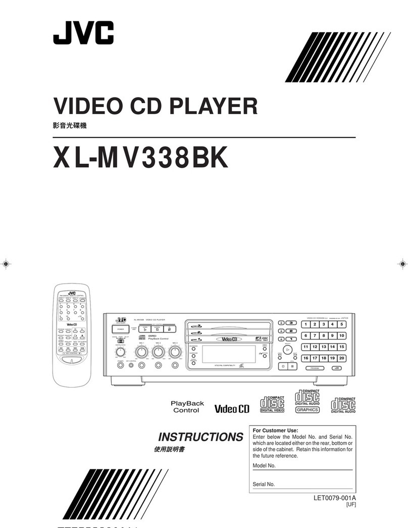
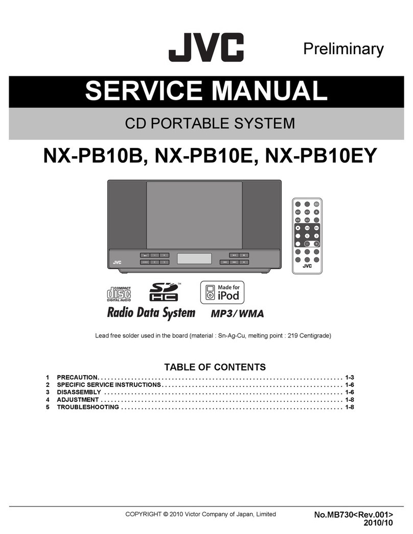
JVC CH-X550 User manual

SERVICE MANUAL
COPYRIGHT © 2004 VICTOR COMPANY OF JAPAN, LIMITED No.49787B
2004/1
CD CHANGER
49787B20041CH-X550,CH-X500
TABLE OF CONTENTS
1 PRECAUTION. . . . . . . . . . . . . . . . . . . . . . . . . . . . . . . . . . . . . . . . . . . . . . . . . . . . . . . . . . . . . . . . . . . . . . . . . 1-3
2 SPECIFIC SERVICE INSTRUCTIONS. . . . . . . . . . . . . . . . . . . . . . . . . . . . . . . . . . . . . . . . . . . . . . . . . . . . . . 1-5
3 DISASSEMBLY . . . . . . . . . . . . . . . . . . . . . . . . . . . . . . . . . . . . . . . . . . . . . . . . . . . . . . . . . . . . . . . . . . . . . . . 1-6
4 ADJUSTMENT . . . . . . . . . . . . . . . . . . . . . . . . . . . . . . . . . . . . . . . . . . . . . . . . . . . . . . . . . . . . . . . . . . . . . . . 1-22
5 TROUBLESHOOTING . . . . . . . . . . . . . . . . . . . . . . . . . . . . . . . . . . . . . . . . . . . . . . . . . . . . . . . . . . . . . . . . . 1-23
Area suffix
E ----------- Continental Europe
CH-X550
CH-X500
w
w
w
.
x
i
a
o
y
u
1
6
3
.
c
o
m
Q
Q
3
7
6
3
1
5
1
5
0
9
9
2
8
9
4
2
9
8
T
E
L
1
3
9
4
2
2
9
6
5
1
3
9
9
2
8
9
4
2
9
8
0
5
1
5
1
3
6
7
3
Q
Q
TEL 13942296513 QQ 376315150 892498299
http://www.xiaoyu163.com

1-2 (No.49787B)
SPECIFICATION
CD CHANGER SECTION Frequency response 5 Hz - 20000Hz
Dynamic range 93dB
S/N ratio 96dB
Distortion 0.01%
Wow & Flutter Less than measurable limit
Output terminal Analog ( 8 pin ×1 ), 1.5V ( full scale )/less than 1k Ω
GENERAL Power requirement Operating voltage DC 14.4 V (11 V - 16 V allowable)
Grounding system Negative ground
Allowable working temperature -10°C to +50°C (14°F to 122°F)
Dimensions (W ×H ×D) 252 mm ×88 mm ×174 mm (9-15/16" ×3-1/2" ×6-7/8")
Mass 2.3 kg (5.1lbs.) (excluding accessories)
w
w
w
.
x
i
a
o
y
u
1
6
3
.
c
o
m
Q
Q
3
7
6
3
1
5
1
5
0
9
9
2
8
9
4
2
9
8
T
E
L
1
3
9
4
2
2
9
6
5
1
3
9
9
2
8
9
4
2
9
8
0
5
1
5
1
3
6
7
3
Q
Q
TEL 13942296513 QQ 376315150 892498299
http://www.xiaoyu163.com
(No.49787B)1-3
SECTION 1
PRECAUTION
1.1 Safety Precautions
!Burrs formed during molding may be left over on some parts of the chassis. Therefore,
pay attention to such burrs in the case of preforming repair of this system.
!Please use enough caution not to see the beam directly or touch it in case of an
adjustment or operation check.
w
w
w
.
x
i
a
o
y
u
1
6
3
.
c
o
m
Q
Q
3
7
6
3
1
5
1
5
0
9
9
2
8
9
4
2
9
8
T
E
L
1
3
9
4
2
2
9
6
5
1
3
9
9
2
8
9
4
2
9
8
0
5
1
5
1
3
6
7
3
Q
Q
TEL 13942296513 QQ 376315150 892498299
http://www.xiaoyu163.com
1-4 (No.49787B)
1.2 Preventing static electricity
Electrostatic discharge (ESD), which occurs when static electricity stored in the body, fabric, etc. is discharged, can destroy the laser
diode in the traverse unit (optical pickup). Take care to prevent this when performing repairs.
1.2.1 Grounding to prevent damage by static electricity
Static electricity in the work area can destroy the optical pickup (laser diode) in devices such as CD players.
Be careful to use proper grounding in the area where repairs are being performed.
(1) Ground the workbench
Ground the workbench by laying conductive material (such as a conductive sheet) or an iron plate over it before placing the
traverse unit (optical pickup) on it.
(2) Ground yourself
Use an anti-static wrist strap to release any static electricity built up in your body.
(3) Handling the optical pickup
• In order to maintain quality during transport and before installation, both sides of the laser diode on the replacement optical
pickup are shorted. After replacement, return the shorted parts to their original condition.
(Refer to the text.)
• Do not use a tester to check the condition of the laser diode in the optical pickup. The tester's internal power source can easily
destroy the laser diode.
1.3 Handling the traverse unit (optical pickup)
(1) Do not subject the traverse unit (optical pickup) to strong shocks, as it is a sensitive, complex unit.
(2) Cut off the shorted part of the flexible cable using nippers, etc. after replacing the optical pickup. For specific details, refer to the
replacement procedure in the text. Remove the anti-static pin when replacing the traverse unit. Be careful not to take too long a
time when attaching it to the connector.
(3) Handle the flexible cable carefully as it may break when subjected to strong force.
(4) It is not possible to adjust the semi-fixed resistor that adjusts the laser power. Do not turn it.
1.4 Attention when traverse unit is decomposed
*Please refer to "Disassembly method" in the text for the CD pickup unit.
• Apply solder to the short land before the flexible wire is disconnected from the connector on the CD pickup unit.
(If the flexible wire is disconnected without applying solder, the CD pickup may be destroyed by static electricity.)
• In the assembly, be sure to remove solder from the short land after connecting the flexible wire.
1M
(caption)
Anti-static wrist strap
Conductive material
(conductive sheet) or iron plate
Short circuit round
(Grounding point)
Pickup
Flexible wire
w
w
w
.
x
i
a
o
y
u
1
6
3
.
c
o
m
Q
Q
3
7
6
3
1
5
1
5
0
9
9
2
8
9
4
2
9
8
T
E
L
1
3
9
4
2
2
9
6
5
1
3
9
9
2
8
9
4
2
9
8
0
5
1
5
1
3
6
7
3
Q
Q
TEL 13942296513 QQ 376315150 892498299
http://www.xiaoyu163.com

(No.49787B)1-5
SECTION 2
SPECIFIC SERVICE INSTRUCTIONS
2.1 How to recognize
C101 C102
C103
C104
C105
C106
C107
C108
C109
C110
C201C202
C203
C204
C205
C206
C208
C209
C501
C502C503
C504
C505
C507
C508
C509
C510
C511
C512
C513
C514
C521
C522
C523
C524
C525
C526
C527
C528
C529
C530
C531
C533
C534
C535
C536
C537
C538
C539
C540
C541
C542
C543
C544
C545
C546
C547
C548
C549
C550
C551
C552
C553
C554
C555
C581
C582
C583
C584
C601
C602
C603
C604
C605
C606
C609
C610
C611
C612
C651
C901
C902
C906
C907
C912 C913
C914
C915
C941
C942
C943
C944
C945
C982
C983 C984
CN503
CN504
CN601
CN904
D101
D581
D911
D912
D913
D921
D941
D951
D981
IC101
IC501
IC521
IC581
IC601
IC602
IC604
IC651
L521
L522
L524
L601
Q101
Q201
Q501
Q581
Q582Q583
Q602
Q901
Q902
Q911 Q921
Q922
Q941
Q942
Q943
Q944
Q971
Q972
Q981
R101
R102
R103
R104
R105
R106
R107
R108
R109
R110
R111
R201
R202
R203
R204
R205
R206
R207
R208
R209
R210
R211
R503
R504
R505
R506
R507
R508
R509
R510
R511
R512
R513
R514
R515
R516
R517
R518
R519
R521
R522
R523
R524
R525
R527
R528
R531
R532
R534
R535
R536
R537
R538
R539
R543
R544
R581
R582
R583
R584
R585
R586
R601
R602
R603
R604
R605
R606
R607
R609
R610
R611
R612
R614
R617
R618
R619
R620
R621
R622
R623
R624
R625
R626
R627
R628
R629
R630
R631
R651
R652
R653
R654
R655
R656
R657
R658
R659
R660
R661
R901
R902
R903
R911
R912
R921
R923
R924
R925
R926
R941
R942
R943
R951
R954
R971
R972
R973
R981
R982
S601
S606
X521
X601
C908
C613
A new board has the display of "LVA10455" in a circuit board.
N3
SERIAL NO.
CD CHANGER
for CAR USE
MODEL NO. CH-X550
VICTOR COMPANY OF JAPAN. LIMITED
DC 12 V NEGATIVE GROUND
MADE IN INDONESIA
A new board has the display of "N3" in a nameplate.
e24
020268
w
w
w
.
x
i
a
o
y
u
1
6
3
.
c
o
m
Q
Q
3
7
6
3
1
5
1
5
0
9
9
2
8
9
4
2
9
8
T
E
L
1
3
9
4
2
2
9
6
5
1
3
9
9
2
8
9
4
2
9
8
0
5
1
5
1
3
6
7
3
Q
Q
TEL 13942296513 QQ 376315150 892498299
http://www.xiaoyu163.com

1-6 (No.49787B)
SECTION 3
DISASSEMBLY
• Perform operations according to the items to be disassembled.
Replacement of the pickup
(1) After removing the exterior (top and bottom).
(2) Proceed to the pickup replacement section.
(3) When applying grease, refer to the exploded view. Use
new grease.
Mechanism section
(1) Remove the exterior (required section only).
(2) The mechanism section is designed so that each unit
can be removed separately.
(3) When reassembling, refer to the assembling precau-
tions. (Use new grease when applying grease.)
3.1 Exterior section
3.1.1 Removing the bottom cover and front panel assembly
(See Fig.1 to 4)
(1) Remove the two screw Ato unlock the mounting direction
knob located on the side of the main unit.
(2) Turn the mounting direction knob in the direction of the ar-
row using a coin, etc. to remove it. (The knob can be re-
moved only when it is set to this position.)
(3) Remove the four top cover fixing screws Bat the triangle
marks on the side of the main unit. (Perform the same op-
eration on both sides.)
(4) Turn the unit upside down so the bottom surface is facing
upward.
(5) Lift the rear edge of the bottom cover slightly and lift the
side by grasping the DIN jack section on the side panel,
then turn it toward the front (raise upward) to remove the
bottom cover.
(6) Unhook the four catches located on both sides of the front
panel, and turn the front panel toward the top cover (lower
down) to remove the front panel.
Fig.1
Fig.2
Fig.3
Fig.4
A
B
Remove A and turn in
the direction of the arrow.
B
B
B
Bottom cover
Knob
Remove A and turn in
the direction of the arrow
BB
A
B
B
Bottom cover
Knob
The front panel can be
separated by raising the cover.
Slightly lift the jack
section to remove.
Bottom cover
Unhook catches
Unhook catches
Front panel
w
w
w
.
x
i
a
o
y
u
1
6
3
.
c
o
m
Q
Q
3
7
6
3
1
5
1
5
0
9
9
2
8
9
4
2
9
8
T
E
L
1
3
9
4
2
2
9
6
5
1
3
9
9
2
8
9
4
2
9
8
0
5
1
5
1
3
6
7
3
Q
Q
TEL 13942296513 QQ 376315150 892498299
http://www.xiaoyu163.com

(No.49787B)1-7
3.1.2 Removing the top cover
(See Fig.5 to 9)
(1) Remove the four damper bracket fixing screws Cto re-
move the damper brackets.
(2) Pull out the dampers, being careful not to damage them.
When reattaching a damper, insert your finger to push out
the center of the damper to mount it on the damper shaft,
as shown in Fig. 6-1.
(3) Turn the damper spring bracket toward the top at a right an-
gle as shown in Fig. 7, then push down the lower side of the
damper spring bracket to lift it off.
(4) Remove the three fixing screws Dand Eon the DIN jack
board assembly.
(5) Lift the changer unit upward.
(6) Remove the damper springs from the mechanism chassis
if required. To reassemble, refer to the diagram below.
Fig.5
Fig.6
Fig.6-1
Fig.7
Fig.8
Fig.8-1
Fig.9
C
C
Damper
Damper bracket
Damper
Damper bracket
C
C
Damper
Damper bracket
Damper bracket
Damper
Apply alcohol to the shaft then immediately
attach the damper. (After attaching, check
that the shaft is correctly inserted.)
Push out with your finger
before attaching
Damper shaft
Damper
Turn to the top position (at a right angle),
then push down to lift off.
Damper spring bracket
Lift the changer unit upward
How to attach the damper springs
Silver
(mechanism side)
Black
(magazine side)
Mechanism
Chassis
Damper spring Damper spring
Remove the flexible ribbon
wire if required
E
E
D
DIN jack board
w
w
w
.
x
i
a
o
y
u
1
6
3
.
c
o
m
Q
Q
3
7
6
3
1
5
1
5
0
9
9
2
8
9
4
2
9
8
T
E
L
1
3
9
4
2
2
9
6
5
1
3
9
9
2
8
9
4
2
9
8
0
5
1
5
1
3
6
7
3
Q
Q
TEL 13942296513 QQ 376315150 892498299
http://www.xiaoyu163.com

1-8 (No.49787B)
3.1.3 Removing the fittings
(See Fig.10)
(1) Remove the fixing screw F.
(2) Unhook the two catches aon the top edge of the fitting, then
unhook the two catches bat the left / right bottom edges.
Fig.10
3.1.4 Removing the main PCB assembly
(See Fig.11)
(1) Remove the power IC fixing screw G.
(2) Remove the four screws Hsecuring the main board as-
sembly.
(3) Disconnect position motor wire connector CN504 from the
main board assembly.
(4) Disconnect sensor board assembly wire connector CN601
from the main board assembly.
(5) Remove the flexible ribbon wire from CN502 on the
traverse mechanism board assembly. When reinstalling
the board boards, refer to the reassembling procedures for
protecting switches, etc.
Fig.11
Catches a
Catches b
Fitting
F
H
CN601
CN504
CN502
H
G
H
Main board
w
w
w
.
x
i
a
o
y
u
1
6
3
.
c
o
m
Q
Q
3
7
6
3
1
5
1
5
0
9
9
2
8
9
4
2
9
8
T
E
L
1
3
9
4
2
2
9
6
5
1
3
9
9
2
8
9
4
2
9
8
0
5
1
5
1
3
6
7
3
Q
Q
TEL 13942296513 QQ 376315150 892498299
http://www.xiaoyu163.com
(No.49787B)1-9
3.2 CD mechanism assembly
3.2.1 Sensor assembly unit
(See Fig.1)
(1) Remove the two screws Isecuring the sensor assembly
unit.
(2) Unhook the spring on the back of the sensor assembly unit
from the holes on the chassis.
3.2.2 Magazine lock arm
(See Fig.1 and 2)
(1) Remove the magazine lock spring from the front side of the
chassis.
(2) Remove the poly-washer csecuring the magazine lock
arm.
(3) Turn the magazine lock arm in the direction of the arrow un-
til the notch is at the dposition to remove it from the chas-
sis.
Fig.1
Fig.2
3.2.3 Positioning motor assembly
(See Fig.3)
(1) Remove the two screws Jsecuring the positioning motor.
(2) Slightly lift the positioning motor assembly to remove it
from the two burrs on the chassis.
Fig.3
Sensor assembly I
Spring
I
Rear Magazine lock spring
Poly-washer c
d
Positioning
motor assembly
J
w
w
w
.
x
i
a
o
y
u
1
6
3
.
c
o
m
Q
Q
3
7
6
3
1
5
1
5
0
9
9
2
8
9
4
2
9
8
T
E
L
1
3
9
4
2
2
9
6
5
1
3
9
9
2
8
9
4
2
9
8
0
5
1
5
1
3
6
7
3
Q
Q
TEL 13942296513 QQ 376315150 892498299
http://www.xiaoyu163.com
1-10 (No.49787B)
3.2.4 Rear slider
(See Fig.4)
(1) Position the unit with the front section facing down. Rotate
the third gear located on the back of the main unit in the di-
rection of the arrow (clockwise).
(2) Shift the rear slider in the direction of the arrow and remove
it at the rear slider mounting position (at the widest hole).
Fig.4
3.2.5 Front slider
(See Fig.5)
(1) Position the unit with the rear section facing down. Rotate
the third gear located on the bottom of the unit in the direc-
tion of the arrow (clockwise) until the front slider is shifted
to the outermost position.
(2) Remove the E-washer securing the front slider to remove
the front slider from the chassis
Fig.5
3.2.6 Top plate
(See Fig.6 and 7)
(1) Remove the nine screws K securing the top plate.
(2) Disconnect the section eattached to the rear of the unit,
then lift the top plate slightly.
(3) Slide the top plate toward the rear of the unit to remove the
upper rod from the top plate.
Fig.6
Fig.7
Can be removed at the stud position
(at the widest hole) Remove
Shift
Third gear
Rear slide
r
Remove the E-washer
Third gear
Front slide
r
Slide and remove the rod inside
Slide
Top plate
K
K
K
Rod
After lifting e
Remove
K
Top plate
w
w
w
.
x
i
a
o
y
u
1
6
3
.
c
o
m
Q
Q
3
7
6
3
1
5
1
5
0
9
9
2
8
9
4
2
9
8
T
E
L
1
3
9
4
2
2
9
6
5
1
3
9
9
2
8
9
4
2
9
8
0
5
1
5
1
3
6
7
3
Q
Q
TEL 13942296513 QQ 376315150 892498299
http://www.xiaoyu163.com
(No.49787B)1-11
3.2.7 Lifter unit
(See Fig.8 and 9)
(1) Unhook the elevator spring located on the front side of the
unit. (Be sure to first unhook the spring from the lifter side
as shown in the upper part of the diagram.)
(2) Lift the lifter unit upward, then remove the lower rod to re-
move the lifter unit from the chassis.
Fig.8
Fig.9
3.2.8 Lifter bracket
(See Fig.10)
(1) Remove the two lifter bracket fixing screws L located on
the back of the lifter unit.
(2) Remove the lower rod.
Fig.10
3.2.9 Side bracket and traverse mechanism assembly
(See Fig.11)
(1) Remove the two side bracket unit fixing screws Mto dis-
connect the side bracket unit from the lifter unit.
(2) Remove the three shafts on the traverse mechanism as-
sembly from the lifter unit.
CAUTION:
For reassembling, refer to the reassembling procedures.
Fig.11
Unhook this part first
Proper
orientation
Spring
Lift up the lifter unit
Lower rod
Lifter unit
L
LLifter bracket
Remove from the lifter unit
Remove from the
lifter unit
M
M
Lifter unit
Side bracket
Traverse mechanism
assembly
w
w
w
.
x
i
a
o
y
u
1
6
3
.
c
o
m
Q
Q
3
7
6
3
1
5
1
5
0
9
9
2
8
9
4
2
9
8
T
E
L
1
3
9
4
2
2
9
6
5
1
3
9
9
2
8
9
4
2
9
8
0
5
1
5
1
3
6
7
3
Q
Q
TEL 13942296513 QQ 376315150 892498299
http://www.xiaoyu163.com
1-12 (No.49787B)
3.2.10 Removing the mechanism board / pickup assembly
(See Fig.12 to 15)
(1) Remove the three screws N fixing the mechanism board
on the back of the traverse mechanism.
(2) Disconnect the two feed motor wires (blue and white), two
spindle motor wires (red and black) and two tray motor
wires (brown and black) that are soldered to the mecha-
nism board.
(3) Short-circuit the grounding point on the mechanism board.
Move the mechanism board without disconnecting the wire
from connector CN501. Solder the short circuit round on
the pickup assembly.
(4) Disconnect the wire from connector CN501 on the mecha-
nism board.
(5) Remove the screw O to remove the feed motor assembly.
(6) Remove the screw Pto remove the shaft holder retaining
the feed slide shaft assembly and the middle gear.
(7) Move the middle gear.
(8) Move the pickup assembly upward from the gear section
and remove it from the traverse chassis assembly.
(9) Remove the two screws Qto remove the rack arm.
(10) Pull out the feed slide shaft assembly.
(11) Remove the screw Rto remove the spring.
CAUTION:
To reattach the mechanism board, connect the pickup flexible
wire to connector CN501 on the mechanism board before un-
soldering the short circuit round. Subsequently, fix the mecha-
nism board using screws.
Fig.12
Fig.13
Fig.14
Fig.15
Brown and black
N
N
Red and black
Blue and white
Mechanism board
CN501
Short circuit round
(Grounding point)
Pickup
Flexible wire
Grounding point
Pickup assembly
Shaft holder
Feed slide
shaft assembly
Middle gear
Feed motor
P
O
Chassis
Remove gears and
motors only when
required.
Rack arm Pull out
R
Q
Spring
w
w
w
.
x
i
a
o
y
u
1
6
3
.
c
o
m
Q
Q
3
7
6
3
1
5
1
5
0
9
9
2
8
9
4
2
9
8
T
E
L
1
3
9
4
2
2
9
6
5
1
3
9
9
2
8
9
4
2
9
8
0
5
1
5
1
3
6
7
3
Q
Q
TEL 13942296513 QQ 376315150 892498299
http://www.xiaoyu163.com
(No.49787B)1-13
3.2.11 Tray motor
(See Fig.16 and 17 )
(1) Remove the two screws Ssecuring the tray motor.
(2) Remove the two screws Tto remove the tray motor as-
sembly from the tray motor holder.
Fig.16
Fig.17
3.2.12 Separation of the chassis (L) assembly and chassis (R) assembly
(See Fig.18 )
(1) Remove the two screws Uretaining the chassis (L) and (R)
assemblies.
(2) Slide the chassis (L) assembly toward the front and detach
it, then remove the chassis (L) upward.
Fig.18
Tray motor assembly
SS
Tray motor
Tray motor holder
T
Front side
UU
Slide and remove upward
as shown by the arrow
Chassis (L) assembly
Chassis (R) assembly
w
w
w
.
x
i
a
o
y
u
1
6
3
.
c
o
m
Q
Q
3
7
6
3
1
5
1
5
0
9
9
2
8
9
4
2
9
8
T
E
L
1
3
9
4
2
2
9
6
5
1
3
9
9
2
8
9
4
2
9
8
0
5
1
5
1
3
6
7
3
Q
Q
TEL 13942296513 QQ 376315150 892498299
http://www.xiaoyu163.com
1-14 (No.49787B)
3.2.13 Precautions on reassembling
CAUTION:
When reassembling, also refer to the disassembling proce-
dures.
3.2.13.1 Mounting the traverse mechanism
(See Fig.19 to 23)
(1) When mounting the pickup assembly, attach the feed slide
shaft assembly to the traverse chassis.Apply E-JC-525
grease to the shaft.
(2) Mount the middle gear and the feed slide shaft to the
traverse chassis and secure them with the screw P
through the shaft holder.
(3) Before mounting the mechanism board, move the pickup to
the outer edge position, then secure the board assembly
using the screw N.
At this time, check that the rest switch is correctly placed.
(4) To mount the rack arm, first move the pickup to the middle
position and secure it with the screws Q.
CAUTION:
To reattach the mechanism board, connect the pickup flexible
wire to connector CN501 on the mechanism board before un-
soldering the short circuit round. Subsequently, fix the mecha-
nism board using screws.
Fig.19
Fig.20
Fig.21
Fig.22
Fig.23
Pickup assembly
Attached to chassis
Shaft holder
Middle gear
Motor
Chassis
Mounting the
feed motor assembly
P
Feed slide shaft
(half coated with grease)
Pickup assembly
Attached to chassis
Shaft holder
Middle gear
Motor
Chassis
Mounting the
feed motor assembly
P
Feed slide shaft
(half coated with grease)
Rack arm
Q
Move the pickup to
the middle position
Mechanism board
N
N
N
CN501
Short circuit round
(Grounding point)
Pickup
Flexible wire
w
w
w
.
x
i
a
o
y
u
1
6
3
.
c
o
m
Q
Q
3
7
6
3
1
5
1
5
0
9
9
2
8
9
4
2
9
8
T
E
L
1
3
9
4
2
2
9
6
5
1
3
9
9
2
8
9
4
2
9
8
0
5
1
5
1
3
6
7
3
Q
Q
TEL 13942296513 QQ 376315150 892498299
http://www.xiaoyu163.com

(No.49787B)1-15
3.2.13.2 Mounting the lifter unit
(See Fig.24 to 26)
(1) Insert the shafts f of the traverse mechanism assembly into
the slide grooves gon the lifter unit.
(2) Shift the hook of the lifter unit to the edge, and shift the slid-
ing lever inside the side bracket unit to the edge as well.
(3) With each hole and lever shifted to the edge, mount the lift-
er unit and side bracket unit from the side. (Check each at-
tached section, and check that the two shafts hof the lifter
unit are correctly inserted into the holes iof the side bracket
unit. After mounting, check that the levers move together. )
(4) Turn the lifter unit upside down.As shown in Fig. 35, slide
the lever 30mm away from the edge, then mount the lifter
bracket assembly.
Fig.24
Fig.25
Fig.26
f
f
f
h
Attach
i
g
g
g
Lifter unit
M
Side bracket
Traverse mechanism
assembly
Shift inside by approx. 30 mm
Expanded view
Lifter bracket
w
w
w
.
x
i
a
o
y
u
1
6
3
.
c
o
m
Q
Q
3
7
6
3
1
5
1
5
0
9
9
2
8
9
4
2
9
8
T
E
L
1
3
9
4
2
2
9
6
5
1
3
9
9
2
8
9
4
2
9
8
0
5
1
5
1
3
6
7
3
Q
Q
TEL 13942296513 QQ 376315150 892498299
http://www.xiaoyu163.com
1-16 (No.49787B)
3.2.13.3 Connection of the chassis (L) assembly and chassis (R) assembly
(See Fig.27 to 29)
(1) Attach the lower rod to the chassis (R) assembly. While
shifting the rod toward the front side, mount the rod on the
lifter unit.With the rod mounted, place the lifter unit on the
chassis (R) assembly.
(2) Combine the chassis (L) and (R) assemblies so that the
hook section j of the chassis (L) assembly is inserted into
the notch of the chassis (R) assembly by sliding it from the
front side.
(3) After engaging, secure with the two screws U.
(4) Attach the tension spring between the lifter unit and the
chassis.
Fig.27
Fig.28
Fig.29
Lower Rod
Lifter unit
Notch Attached
j
Slide to engage
Combine with (R) chassis
Set last (lifter side)
Proper
orientation
Tension spring
Set first
(chassis side)
U
Chassis (L) assembly
U
Chassis (R) assembly
w
w
w
.
x
i
a
o
y
u
1
6
3
.
c
o
m
Q
Q
3
7
6
3
1
5
1
5
0
9
9
2
8
9
4
2
9
8
T
E
L
1
3
9
4
2
2
9
6
5
1
3
9
9
2
8
9
4
2
9
8
0
5
1
5
1
3
6
7
3
Q
Q
TEL 13942296513 QQ 376315150 892498299
http://www.xiaoyu163.com
(No.49787B)1-17
3.2.13.4 Mounting the top plate
(See Fig.30 to 33)
(1) Mount the upper rod on the lifter side l and set it on the rear
of the top plate, then mount the other end of the upper rod
to m.
(2) Check that the five points (n, o, p, sand r) are correctly po-
sitioned.
When mounting section s, set it so that section t of the lifter
unit is pinched by the bending section of the top plate.
(3) Secure the top plate with six fixing screws K.
Fig.30
Fig.31
Fig.32
Fig.33
Upper rod
m
l
K
K
K
Top plate
Section t
Lifter Unit
Point r
Expanded view of mounting s
nops
r
w
w
w
.
x
i
a
o
y
u
1
6
3
.
c
o
m
Q
Q
3
7
6
3
1
5
1
5
0
9
9
2
8
9
4
2
9
8
T
E
L
1
3
9
4
2
2
9
6
5
1
3
9
9
2
8
9
4
2
9
8
0
5
1
5
1
3
6
7
3
Q
Q
TEL 13942296513 QQ 376315150 892498299
http://www.xiaoyu163.com
1-18 (No.49787B)
3.2.13.5 Mounting the front slider and rear slider
(See Fig.34 and 35)
(1) Position the unit with the rear side facing down, then rotate
the third gear in the direction of the arrow (clockwise) until
the lift arm comes to the position at which the holes are ex-
posed, as shown in Fig. 34
(2) Mount the front slider from the top. Rotate the third gear
counterclockwise until the hole of the slider is lined up with
the right hole of the stud, as shown in Fig. 34
(3) Mount the E-washer on the shaft.
(4) Position the unit with the front side facing down, then
mount the rear slider. Check that the u, vand wpositions
are correctly mounted as shown in Fig. 35.
(5) Rotate the third gear in the direction of the arrow (counter-
clockwise) until the lifter unit is at the top position.
Fig.34
Fig.35
Stud
E-Washer
Front slider
Check after mounting
Set so the holes
are exposed
Position so
that the stud
and right hole
are lined up
Rotate the third gear
to move the slider
Rotate until the
holes are lined up
uvw
Rotate the third gear
to move the slider
w
w
w
.
x
i
a
o
y
u
1
6
3
.
c
o
m
Q
Q
3
7
6
3
1
5
1
5
0
9
9
2
8
9
4
2
9
8
T
E
L
1
3
9
4
2
2
9
6
5
1
3
9
9
2
8
9
4
2
9
8
0
5
1
5
1
3
6
7
3
Q
Q
TEL 13942296513 QQ 376315150 892498299
http://www.xiaoyu163.com
(No.49787B)1-19
3.2.13.6 Mounting the sensor board assembly
(See Fig.36)
(1) Attach the longer spring to the white resin, and attach the
shorter spring temporarily to the sensor assembly bracket.
(2) Mount the sensor assembly so that the shaft of the lift arm
is inserted into the longer hole on the white resin located on
the back of the sensor board assembly.
(3) Attach the shorter spring to the hook of the lift arm.
Fig.36
3.2.13.7 Mounting the main PC board assembly
(See Fig.37)
(1) Rotate the third gear clockwise until section x of the front
slider and the third hole from the right are lined up.(Be sure
to set properly. If incorrectly set, the switches on
the board assembly may be damaged.)
(2) After they are correctly positioned, mount the main board
assembly.
Fig.37
Sensor assembly fixing screws
A
ttach
temporarily
Shorter spring
Longer spring
Shorter
spring
II
x
Position so that the slider hole and
third hole from the right are lined up
w
w
w
.
x
i
a
o
y
u
1
6
3
.
c
o
m
Q
Q
3
7
6
3
1
5
1
5
0
9
9
2
8
9
4
2
9
8
T
E
L
1
3
9
4
2
2
9
6
5
1
3
9
9
2
8
9
4
2
9
8
0
5
1
5
1
3
6
7
3
Q
Q
TEL 13942296513 QQ 376315150 892498299
http://www.xiaoyu163.com
1-20 (No.49787B)
3.2.13.8 Pickup replacement procedure
(See Fig.38 to 44)
(1) Remove the bottom cover, front panel and top cover from
the exterior section.
(2) Unplug the flexible ribbon wire from connector CN502 on
the traverse mechanism PC board assembly.
(3) Turn the rear slider and third gear in the lifter section coun-
terclockwise until the traverse mechanism assembly is in
the lowermost (bottom) position.
(4) Unsolder the two wires (black and brown) connected to the
tray motor.
(5) Remove the two screws Mfrom the round holes on the
chassis (R) assembly to remove the lifter bracket (L).
(6) Remove the lower rod.
(7) Disconnect the two feed motor wires (blue and white), two
spindle motor wires (red and black) and two tray motor
wires (brown and black) that are soldered to the mecha-
nism board.
(8) Short-circuit the grounding point on the mechanism board.
Move the mechanism board without disconnecting the wire
from connector CN501. Solder the short circuit round on
the pickup assembly.
(9) Disconnect the wire from connector CN501 on the mecha-
nism board.
(10) Remove the three fixing screws Nfrom the round holes on
the chassis (R) assembly to remove the traverse mecha-
nism board assembly.
(11) Remove the pickup shaft holder fixing screw Pto remove
the pickup assembly.
CAUTION:
When replacing the pickup, be sure to apply counter-
measures against static electricity (grounding the opera-
tion table, wrist band and soldering iron). To remove it,
first short-circuit the grounding point on the mechanism
board, then lift the mechanism board assembly with
CN501 connected. Next, short-circuit the grounding
point on the pickup main unit, then unplug the pickup
flexible board from connector CN501.
CAUTION:
When reassembling, perform in the reverse order.
(12) Remove the two rack arm fixing screws Q.
Pull out the feed slide shaft.
Remove the shaft holder fixing screw R.
(13) When mounting the lifter bracket after replacing the pickup,
shift the lifter unit lever approx. 30 mm towards the inside,
then mount the lifter bracket.
Fig.38
Fig.39
Fig.40
Fig.41
Third gear
M
CN502
Unsolder
Lifter bracket (L)
M
Main PCB assembly
Feed moto
r
assembly
NN
N
CN501
Tray motor
assembly
Unsolder
Traverse mechanism
board assembly
Grounding point
P
Pickup assembly
Shaft holder
Spindle motor
Short circuit round
(Drounding point)
Pickup
Flexible wire
w
w
w
.
x
i
a
o
y
u
1
6
3
.
c
o
m
Q
Q
3
7
6
3
1
5
1
5
0
9
9
2
8
9
4
2
9
8
T
E
L
1
3
9
4
2
2
9
6
5
1
3
9
9
2
8
9
4
2
9
8
0
5
1
5
1
3
6
7
3
Q
Q
TEL 13942296513 QQ 376315150 892498299
http://www.xiaoyu163.com
Other manuals for CH-X550
2
This manual suits for next models
1
Table of contents
Other JVC CD Player manuals