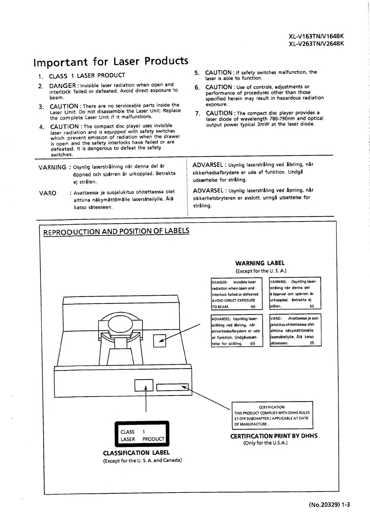
JVC XL-V163TN User manual

4
XL-V163TN/V164BR
XL-V263TN/V264BK
7
no
=O
SERVICE
MANUAL
XL-Vi63TN/V164BK
XL-V263TN/V264BK
ahisir
DIGITAL
AUDIO
fPXAAP
IT
IATLs
oI
TET
UF
Bedi
BIL
Component
(XL-V163TN/XL-V164BK)
fete.
Vie
ER
mil"
¢
oUF
TET
OS
kot CIN
Il!/Remote
|i!
Control
Component
(XL-V263TN/XL-V264BK)
Note:
*
XL—-V163TN/XL—-V164BK
and
XL—V263TN/XL-V264BK
are
completely
same
in
their
structure,
except
for
the
remote
controller.
*
XL-V163TN
and
XL—-V164BK
are
completely
same
in
their
structure,
except
for
their
outlook
colours,
also
XL-V263TN
and
XL-V264BK.
Contents
Safety
Precautions
crc
=
2
Maintenance
of
Laser
Pickup
cvirvrt
1-28
Important
for
Laser
Products
«srt
aad
Replacement
of
Laser
Pickup
ctr
1-28
LAStrUCTION
Book:
ssrrrcicreterienee
ten
cenees
14
Adjustment
Procedures
strstr
1-29
Description
of
ICs
crt
1-15
Troubleshooting
crt
1-31
Internal
Connections
of
Block
Diagram
vresstetereeeeseeeren
Insertion
FL
Display
Tube
ct
seeeees
P28
Printed
Circuit
Board
ctr
Insertion
Application
Points
for
Grease
«tts:
1
—24
Parts:
List.
sscesssnteetescteb
erred
eteernaes
Insertion
Disassembly
Procedures
strttttrtrs
1-25
Flow
of
Functional
Operation
Until
TOC
is
read
crtretetteere
tea?
oe
No.
20392
COPYRIGHT
©
1993
VICTOR
COMPANY
OF
JAPAN,
LTD.
Mar.
1993

XL-V163TN/V164BK
XL-V263TN/V264BK
Ww
Safety
Precautions
.
The
design
of
this
product
contains
special
hardware
and
many
circuits
and
components
specially
for
safety
purposes.
For
continued
protection,
no
changes
should
be
made
to
the
original
design
unless
authorized
in
writing
by
the
manufacturer.
Replacement
parts
must
be
identical
to
those
used
in
the
original
circuits.
Services
should
be
performed
by
qualified
personnel
only.
.
Alterations
of
the
design
or
circuitry
of
the
product
should
not
be
made.
Any
design
alterations
of
the
product
should
not
be
made.
Any
design
alterations
or
additions
will
void
the
manufacturer's
warranty
and
will
further
relieve
the
manufacture
of
responsibility
for
personal
injury
or
property
damage
resulting
therefrom.
.Many
electrical
and
mechanical
parts
in
the
products
have
special
safety-related
characteristics.
These
characteristics
are
often
not
evident
from
visual
inspection
nor
can
the
protection
afforded
by
them
necessarily
be
obtained
by
using
replacement
components
rated
for
higher
voltage,
wattage,
etc.
Replacement
parts
which
have
these
special
safety
characteristics
are
identified
in
the
Parts
List
of
Service
Manual.
Electrical
components
having
such
features
are
identified
by
shading
on
the
schematics
and
by
(A\)
on
the
Parts
List
in
the
Service
Manual.
The
use
of
a
substitute
repalcement
which
does
not
have
the
same
safety
characteristics
as
the
recommended
replacement
parts
shown
in
the
Parts
List
of
Service
Manual
may
create
shock,
fire,
or
other
hazards.
The
leads
in
the
products
are
routed
and
dressed
with
ties,
clamps,
tubings,
barriers
and
the
like
to
be
separated
from
live
parts,
high
temperature
parts,
moving
parts
and/or
sharp
edges
for
the
prevention
of
electric
shock
and
fire
hazard.
When
service
is
required,
the
original
lead
routing
and
dress
should
be
observed,
and
it
should
be
confirmed
that
they
have
been
returned
to
normal,
after
re-assembling.
.
Leakage
currnet
check
(Electrical
shock
hazard
testing)
After
re-assembling
the
product,
always
perform
an
isolation
check
on
the
exposed
metal
parts
of
the
product
(antenna
terminals,
knobs,
metal
cabinet,
screw
heads,
headphone
jack,
contorl
shafts,
etc.)
to
be
sure
the
product
is
safe
to
operate
without
danger
of
electrical
shock.
Do
not
use
a
line
isolation
transformer
during
this
check.
@
Plug
the
AC
line
cord
directly
into
the
AC
outlet.
Using
a
“Leakage
Current
Tester”,
measure
the
leakage
current
from
each
exposed
metal
parts
of
the
cabinet
,
particularly
any
exposed
metal
part
having
a
return
path
to
the
chassis,
to
a
known
good
earth
ground.
Any
leakage
current
must
not
exceed
0.5mA
AC
(r.m.s.).
®
Alternate
check
method
Plug
the
AC
line
cord
directly
into
the
AC
outlet.
Use
an
AC
voltmeter
having,
1,000
ohms
per
volt
or
more
sensitivity
in
the
following
manner.
Connect
a
1,500Q
10
W
resistor
paralleled
by
a
0.15
uF
AC-type
capacitor
between
an
exposed
metal
part
and
a
known
good
earth
ground.
Measure
the
AC
voltage
across
the
resistor
with
the
AC
voltmeter.
Move
the
resistor
connection
to
each
exposed
metal
part,
particularly
any
exposed
metal
part
having
a
return
path
to
the
chassis,
and
meausre
the
AC
voltage
across
the
resistor.
AC
VOLTMETER
(Having
1000
ohms/olts,
or
more
sensitivity.)
Now,
reverse
the
plug
in
the
AC
outlet
and
Place
this
repeat
each
measurement.
Any
voltage
reper
measured
must
not
exceed
0.75
V
AC
(r.m.s.).
15000
10W
metal
part.
This
corresponds
to
0.5
mA
AC
(r.m.s.).
Good
earth
ground
Warning
.
This
equipment
has
been
designed
and
manufactured
to
meet
international
safety
standards.
.
It
is
the
legal
responsibility
of
the
repairer
to
ensure
that
these
safety
standards
are
maintained.
.
Repairs
must
be
made
in
accordance
with
the
relevant
safety
standards.
.
It
is
essential
that
safety
critical
components
are
replaced
by
approved
parts.
.
If
mains
voltage
selector
is
provided,
check
setting
for
local
voltage.
1-2
(No.
20392)

XL-V163TN/V164BK
XL-V263TN/V264BK
Important
for
Laser
Products
CLASS
1
LASER
PRODUCT
5.
CAUTION:
if
safety
switches
malfunction,
the
laser
is
able
to
function.
2.
DANGER:
Invisible
laser
radiation
when
open
and
interlock
failed
or
defeated.
Avoid
direct
exposure
to
6.
CAUTION
:
Use
of
controls,
adjustments
or
performance
of
procedures
other
than
those
bean.
specified
herein
may
result
in
hazardous
radiation
3.
CAUTION:
There
are
no
serviceable
parts
inside
the
exposure.
Laser
Unit.
Do
not
disassemble
the
Laser
Unit.
Replace
; :
it
if
ie
malfunctions.
7.
CAUTION
:
The
compact
disc
player
provides
a
She:
Come
plese:
Fascha
a
ole
ren
on
laser
diode
of
wavelength
780-790nm
and
optical
4.
CAUTION
:
The
compact
disc
player
uses
invisible
output
power
typical
3mW
at
the
laser
diode.
laser
radiation
and
is
equipped
with
safety
switches
which
prevent
emission
of
radiation
when
the
drawer
is
open
and
the
safety
interlocks
have
failed
or
are
defeated.
It
is
dangerous
to
defeat
the
safety
switches.
VARNING
:
Osynlig
laserstralning
nar
denna
del
ar
:
ADVARSEL
:
Usynlig
laserstraling
ved
&bning,
nar
éppnad
och
sparren
4r
urkopplad.
Betrakta
:
sikkerhedsafbrydere
er
ude
af
funktion.
Undga
ej
stralen.
:
udsaettelse
for
straling.
VARO
:
Avattaessa
ja
suojalukitus
ohitettaessa
olet
:
ADVARSEL
:
Usynlig
laserstraling
ved
pning,
nar
alttiina
ndkym&ttomalie
lasersateilylle.
Ala
:
sikkerhetsbryteren
er
avslott.
unngéa
utsettelse
for
katso
sateeseen.
:
straling.
San
nnn
nn
Udit
nnn
REPRODUCTION
AND
POSITION
OF
LABELS
WARNING
LABEL
(Except
for
the
U.S.A.)
DANGER:
_
invisible
laser
radiation
when
open
and
interlock
failed
or
defeated.
AVOID
DIRECT
EXPOSURE
TO
BEAM.
{e)
VARNING:
Osynling
laser-
stréling
nar
denna
del
a
Oppnad
och
sparren
ar
urkoppled.
Betrakta
ej
stalen.
(s)
IADVARSEL:
Usynling
laser-
straling
ved
abning,
nar
sikkerhedsafbrydere
er
ude
at
funktion.
Undgdudseet-
(d)
VARO:
Avattaessa
ja
suo-
jalukitus
ohitettaessa
olet
alttiina
nakymattomalle
lasersateilytle.
Ala
katso
sAteeseen.
(VW)
telse
for
straling.
CERTIFICATION
THIS
PRODUCT
COMPLIES
WITH
DHHS
RULES
21
CFR
SUBCHAPTER
J
APPLICABLE
AT
DATE
OF
MANUFACTURE
.
CLASS
1
LASER
PRODUCT
CERTIFICATION
PRINT
BY
DHHS
(Only
for
the
U.S.A.)
CLASSIFICATION
LABEL
(Except
for
the
U.S.
A.
and
Canada)
(No.20329)
1-3

XL-V163TN/V
164BK
XL-V263TN/V264BK
IMPORTANT
for
the
U.K.
DO
NOT
cut
off
the
mains
plug
from
this
equipment.
If
the
plug
fitted
is
not
suitable
for
the
power
points
in
your
home
or
the
cable
is
too
short
to
reach
a
power
point,
then
obtain
an
appropriate
safety
approved
extension
lead
or
consult
your
dealer.
BE
SURE
to
replace
the
fuse
only
with
an
identical
approved
type,
as
originally
fitted.
If
nontheless
the
mains
plug
is
cut
off
ensure
to
remove
the
fuse
and
dispose
of
the
plug
immediately,
to
avoid
a
possible
shock
hazard
by
inadvertent
connection
to
the
mains
supply.
If
this
product
is
not
supplied
fitted
with
a
mains
plug
then
follow
the
instructions
given
below:
IMPORTANT.
DO
NOT
make
any
connection
to
the
termina!
which
is
marked
with
the
letter
E
or
by
the
safety
earth
symbol
or
coloured
green
or
green-and-yellow.
The
wires
in
the
mains
lead
on
this
product
are
coloured
in
accordance
with
the
following
code:
Blue
:
Neutral
Brown:
Live
As
these
colours
may
not
correspond
with
the
coloured
markings
identifying
the
terminals
in
your
plug
proceed
as
follows:
The
wire
which
is
coloured
blue
must
be
connected
to
the
terminal
which
is
marked
with
the
letter
N
or
coloured
black.
The
wire
which
is
coloured
brown
must
be
connected
to
the
terminal
which
is
marked
with
the
letter
L
or
coloured
red.
IF
IN
DOUBT
-
CONSULT
A
COMPETENT
ELECTRICIAN.
THIS
UNIT
IS
PRODUCED
TO
COMPLY
WITH
DIREC-
TIVE
76/889/EEC.
CAUTION
To
reduce
the
risk
of
electrical
shocks,
fire,
etc.:
1.
Do
notremove
screws,
covers
or
cabinet.
2.
Do
not
expose
this
appliance
to
rain
or
moisture.
1-4(No.20329)

IMPORTANT
FOR
LASER
PRODUCTS
REPRODUCTION
OF
LABELS
@
CLASSIFICATION
LABEL,
PLACED
ON
REAR
ENCLOSURE
(Except
for
the
U.S.A.)
CLASS
1
PRODUCT
LASER
1.
CLASS
1
LASER
PRODUCT
2.
DANGER:
Invisible
laser
radiation
when
open
and
interlock
failed
or
defeated.
Avoid
direct
exposure
to
beam.
3.
CAUTION:
Do
not
open
the
top
cover.
There
are
no
user
serviceable
parts
inside
the
unit;
leave
all
servicing
to
qualified
serv-
ice
personnel.
XL-V163TN/V164BK
XL-V263TN/V264BK
@
WARNING
LABEL,
PLACED
INSIDE
THE
UNIT
(Except
for
the
U.S.A.)
DANGER:
Invisible
laser
radiation
when
open
and
interlock
failed
or
defeated.
AVOID
DIRECT
EXPOSURE
TO
BEAM.
(e)
ADVARSEL:
Usynlig
laser-
straling
ved
abning,
nar
sikkerhedsafbrydere
er
ude
af
funktion,
Undga
udseet-
telse
for
straling
(d)
On
the
back
fold-out
page
of
this
page
are
illustra-
tions
of
the
front
panel,
the
display
and
the
remote
control
unit.
Please
see
reverse
side
of
this
fold-out
page
when
you
read
the
instructions
corresponding
by
number.
Wty
ei)
TL}
Ea
Be a—
BS
=
===
SS
Be
SS
EE
=
=
=
SS
Zz
==
SS
Z=———S
Ee
==
=
Be
=
SS
ZEEE
ss
a
==
oo
BA"
VARNING:
Osynlig
laser-
stralning
nar
denna
del
ar
dppnad
och
sparen
ar
urkopplad.
Betrakta
—¢j
stralen.
(3)
VARO:
Avattaessa
ja
suo-
jalukitus
ohitettaessa
olet
alttiina
—
ndkymattmalle
lasersateilylle,
Ala
katso
sateeseen,
(f
E406507-001
(No.20392)1-5

XL-V163TN/V
164BK
XL-V263TN/V264BK
FRONT
PANEL
PoleR
XLv2e'|
COMPAC|'
DISC
PLIVER
$$$
risir
sia
a
HS
iia
ek
oe
a
%
=|
|
|
=
=
=F
Caer
remepueve
C—O
OO
o
2
DY
ao
a
oe
er
=
o—_O
eal
ree
rel
||
<tr
tit
FIG.
1
DISPLAY
@
RAMDOM|
—_
EDIT—|
EPEAT.
1)
REMOTE
CONTROL
UNIT
1-6
(No.20392)

Precaution
iN
USE
.......csceeceneeseeeeteeeteeneeres
1
How
to
handle
a
compact
disc
COMPU
LINK
Control
system
.
DDRP
SySterm
......e
ee
eeeeeeeees
How
to
install
the
batteries
Connection
diagram
......
Description
and
functions
.
Display
..
Remote
control
unit.
How
to
operate
...
Troubleshooting
.
Specifications
HSITONA
Thank
you
for
purchasing
this
JVC.
product.
Before
you
begin
operating
this
unit,
please
read
the
instructions
carefully
to
be
sure
you
get
the
best
possible
performance.
if
you
have
any
question,
consult
your
JVC
dealer.
CORD
ee
N
4
ESIUIS
WS
Holt
GER
‘Control
System
XL-V163TN,
XL-V164BK
POuADIIT
FAIZ
WTI
UF
bE
CIN
Hi
Ren
Til/Remote
/iil
Tt
Control
System
XL-V263TN,
XL-V264BK
COMPU
LINK
(remote)
Control
Systemis
a
convenient
system
using
COMPU
LINK-1,
3/SYNCHRO
terminals
on
the
rear
panel.
For
further
details,
refer
to
page
2.
e °
«P
DYNAMICS
DETECTION
RECORDING
PROCESSOR
This
product
can
be
combined
with
a
DDRP
(Dynamic
Detection
Recording
Processor)
system
(compactdisc
player
+
cassette
deck,
etc.)
to
enable
setting
the
optinum
recording
level
automatically.
For
further
details,
refer
to
page
2.
Notes:
©
XL-V163TN/XL-V164BK/XL-V263TN/XL-
V264BK
has
almost
the
same
function.
Their
differences
are
as
follows:
Model
Name
Remote
Control
XL-V163TN
Titanium
XL-Vi64BK
Black
No
XL-V263TN
Titanium
Yes
XL-V264BK
Black
XL-V163TN/V164BK
XL-V263TN/V264BK
PRECAUTION
IN
USE
HOW
TO
HANDLE
A
COMPACT
DISC
installation
—
Select
a
location
which
is
level,
dry
and
Nelther
too
cold
nor
too
hot
(between
5°C
(41°F)
and
35°C(95°F).
—
Avoid
a
dusty
location
or
a
location
subject
to
vibrations.
Power
—
When
unplugging
from
the
wail
outlet,
always
pull
on
the
plug,
not
on
the
power
cord.
Malfunctions,
etc.
~
Do
not
insert
any
metallic
object
into
the
player.
—
The
discs
to
be
played
on
this
player
are
limited
to
those
bearing
the
mark
below
(Fig.
4).
—
Placing
anything
other
than
a
compact
disc
on
the
tray
may
cause
the
player
to
malfunction.
—
If
something
goes
wrong,
turn
the
power
off
immediately.
If
the
same
phenomenon
occurs
when
the
power
is
turned
on
again,
turn
the
power
off
and
consult
your
JVC
dealer.
Volume
setting
As
acompact
disc
causes
almost
no
noise,
it
is
difficult
to
set
the
volume
level
by
listening
to
noise
as
in
the
case
of
an
ordinary
analog
turntable
or
a
tape
deck.
If
the
volume
level
is
raised
too
much
because
the
beginning
of
the
selection
is
quiet,
the
speakers
may
be
dam-
aged
by
a
sudden
increase
in
the
sound
level.
Condensation
Asthe
compact
disc
player
uses
optical
parts,
moving
it
from
a
cold
to
warm
place
or
using
itina
room
subject
to
excessive
humidity
or
in
a
room
where
a
fire
has
just
been
lit
may
cause
condensation
on
the
optical
parts.
This
phenomenon
may
prevent
the
light
from
be-
ing
correctly
transmitted,
and
may
cause
noise
or
malfunction.
\f
dew
condenses
and
the
player
does
not
functioncorrectly,
leave
it
on
for
several
hours
with
the
power
turned
on.
if
the
player
does
not
function
even
after
such
period,
consult
your
dealer.
Note:
¢
When
this unit
ls
placed
near
a
tuner
ora
receiver,
noise
may
occur.
If
thishappens,
move
this
unit
as
far
from
the
tuner
or
the
receiver
as
possible,
or
briefly
turn
off
the
power
of
the
unit.
COMPACT
DIGITAL
AUDIO
Fig
4
Since
compact
discs
are
made
of
plastic,
they
can
be
easily
damaged;
if
the
disc
gets
dirty,
dusty,
damaged
or
warped,
the
sound
will
not
be
picked
up
correctly,
and
such
discs
may
cause
the
player
to
malfunction.
When
handling
com-
pach
disc,use
the
following
precautions.
.
Do
not
touch
the
surface
of
the
disc
(reflective
silver
i.e.
the
side
without
the
label)
When
handling
the
discs.
Storage
Make
sure
tokeep
discs
in
their
cases.
Ifdiscs
are
piled
on
top
of
the
one
another
without
cases,
they
can
be
damaged.
Do
not
put
discs
in
a
location
exposed
to
direct
sunlight
or
in
a
place
with
high
temperature
and
hu-
midity.
Avoid
leaving
discs
in
your
car.
Maintenance
of
discs
(Fig.
5)
When
fingerprints
and
dirt
adhere
to
a
disc,
wipe
the
disc
off
with
a
soft,
dry
cloth
from
the
inside
towards
the
outside.
If
it
is
dificult
to
clean,
wipe
the
dics
with
a
cloth
moistened
with
water.
Do
not
use
record
cleaners,
benzine,
alcohol
or
antistatic
agent.
Do
not
damage
the
label
side
or
stick
paper
or
adhesive
to
the
surface.
In
the
case
of
an
8
cm
(3°)
single
CD,
place
it
in
the
disc
hold,
for
an
8
cm
(3")
disc,
within
the
tray.
(No.20392)1-7

XL-V163TN/V164BK
XL-V263TN/V264BK
COMPU
LINK
CONTROL
SYSTEM
The
Compu
Link
Remote
Control
System
con-
trols
relative
operations
between
components
automatically
and
facilitates
various
operations.
This
is
a
system
originated
and
developed
by
JVC
for
facilitating
various
system
operations.
There
are
two
versions
of
this
system;
version
1
and
3.
(For
version
1
components,
“COMPU
LINK-1
SYNCHRO"
is
marked
on
the
rear
panel.
For
version
3
components,
“COMPU
LINK-3
SYNCHRO”
is
marked
on
the
rear
panel.
This
unit
belongs
to
version
3.)
The
version
3
system
control
relative
functions
between
this
unit
and
an
amplifier
or
receiver,
in
addition
to
all
of
the
functions
of
version
1.
Automatic
Source
Selection
When
the
provided
remote
cable
are
used
for
connecting
this
unit
to
other
components
which
have
COMPU
LINK
-1,
3/SYNCHRO
terminals,
the
switch-over
of
all
system
components
is
possible
with
simple
one-touch
of
the
source
selector
button
of
the
JVC
amplifier
or
receiver.
By
doing
this,
the
corresponding
component
will
start
playing
automatically.
The
source
select
button
of
the
remote
control
unit
or
the
select
button
of
the
desired
componentcan
also
be
use
for
this
purpose.
When
the
components
have
been
switch
over,
the
previously
used
component
will
stop
playing
within
five
seconds.
Synchronized
Recording
If
a
cassette
deck
with
COMPU
LINK-1,
3/
SYNCHRO
terminals
is
connected
with
the
remote
cable
supplied,
synchro
recording
be-
comes
possible.
Synchronized
recording
refers
to
the
process
in
which
the
cassette
deck
starts
recording
in
the
synchronism
with
the
CD
player.
Perform
the
synchronized
recording
as
follows.
1.
Set
the
cassette
deck
to
the
REC/PAUSE
mode
in
accordance
with
the
procedures
in
the
instructions.
2.
If
you
want
programmed
recordings,
pro-
gram
the
desired
selections
in
any
order
you
wish
to
hear
them.
3.
Press
the
[PLAY»/m
PAUSE]
button
of
the
CD
player.
By
doing
so,
the
cassette
deck
is
placed
in
the
record
mode
and
synchronized
with
the
CD
player
for
recording.
Synchro-
nized
recording
thus
can
be
made
possible.
Automatic
Source
Selection
This
feature
works
only
when
this
unit
is
con-
nected
to
an
amplifier
or
receiver
with
COMPU
LINK-3
SYNCHRO
terminalis.
By
pressing
the
[PLAY/t!
PAUSE]
or
(p>)
but-
ton,
you
can
turn
on
this
unit
and
the
connected
equipment
(amplifier
or
receiver),
and
by
turning
off
the
connected
equipment,
you
can
turn
off
this
unit.
Notes:
¢
Synchronized
recording
stops
automati-
cally
when
the
CD
player
stops
playing.
©
To
cancel
synchronized
recording,
press
the
{a
STOP/CLEAR]
button
of
the
CD
player
or
cassette
deck.
CAUTION:
e
When
the
REC/PAUSE
mode
is
set
by
pressing
[PAUSE
(11
)]
button
after
press-
Ing
the
[REC
(0
)]
and
[PLAY
(
>
)]
but-
tons
simultaneously,
synchronized
re-
cording
Is
not
possible.
For
details,
refer
to
the
Instructions
of
the
cassette
deck.
Abnormal
operation
will
result
ifthe
power
supply
of
the
components)
is
Interrupted.
if
this
happens,
you
must
start
all
over
again.
Ensure
that
the
COMPU
LINK-1,
3/
SYNCHRO
terminals
of
the
individual
com-
ponents
are
connected
with
the
provided
remote
cables.
Also
be
sure
to
fully
read
the
instructions
for
each
component.
DDRP
(Dynamics
Detection
Recording
Processor)
The
Dynamics
Detection
Recording
Processor
(DDRP)
detects
the
peak
level
of
the
music
being
performed
and
outputs
the
optimum
re-
cording
level.
When
the
(DDRP)
button
is
pressed,
the
DDRP
indicator
starts
to
flash,
the
letters
“ddrp"
run
along
the
display
and
the
volume
is
reset
to
the
maximum
value.
Each
time
a
new
peak
level
is
detected
during
peak
search
mode,
the
PHONES
OUTPUT
LEVEL
setting
is
reduced
and
the
optimum
level
is
set.
The
time
taken
for
peak
search
varies
with
the
total
performance
time
of
the
music
being
scanned,
but
is
around
two
minutes
for
a
40
minute
performance
time.
DORP
Recording
The
combination
of
the
DDRP
function
and
synchro
recording
makes
recording
on
tape
cassette
very
easy.
There
are
two
recording
methods
-
according
to
which
type
of
cassette
deck
is
being
used.
1.
Incombination
with
a
DDRP
compatible
JVC
cassette
deck
:
Peak
search
is
initiated
by
pressing
the
[DDRP]
button.
As
soon
as
the
peak
search
is
terminated,
recording
starts.
The
cassette
deck
should
be
operated
in
accordance
with
the
instructions
supplied
with
it.
1-8
(No.20392)
2.
In
combination
with
any
JVC
cassette
deck
not
DDRP-compatible
:
Where
connection
is
made
to
a
cassette
deck
not
DDRP-compatible,
via
the
synchro
terminals,
pressing
the
[DDRP]
button
will
start
the
recording
process.
In
this
case,
the
cassette
deck
input
level
will
not
be
automaticaily
set.
Where
a
none
DDRP-compatible
cassette
deck
is
used,
a
preliminary
recording
should
be
made
in
order
to
ascertain
ideal
input
levels
-
the
input
level
being
then
set
up
in
accordance
with
the
instructions
for
the
cassette
deck.
If
the
input-level
knob
is
subsequently
reset
to
the
same
position,
this
enables
recording
at
the
optimum
level
to
be
done,
without
resetting
every
time.
ODRP
Cancel
Press
the
[4
OPEN/CLOSE]
button
to
cancel
DDRP
mode.
Note
¢
The
graphic
equalizer
should
not
be
used
during
DDRP
recording.
Using
this
facility
will
disturb
the
optimum
recording
level
set-
ting
just
found
by
the
DDRP.
Please
do
not
turn
off
the
power
to
the
CD
player
while
the
DDRP
mode
is
active.
If
this
should
be
turned
off
by
accident
then
the
cassette
deck
should
also
be
switched
off
for
a
few
seconds
in
order
to
clear
the
DDRP
recording
mode
from
the
cassette
deck.
¢
When
the
cassette
deck
is
connected
via
the
synchro
terminals,
itis
set
in
recording
mode
when
DDRP
is
pressed.
Take
care,
there-
fore,
not
to
erase
a
tape
by
mistake.
Supplementary
Notes
e
For
successful
DDAP
recording,
make
sure
to
turn
on
the
cassette
deck
before
starting
the
recording.
e
Whenever
any
addition
or
cancellation
is
made
to
the
music
tracks
programme,
the
DDRP
mode
is
cancelled.
¢
DDRP
recording
is
automatically
stopped
when
the
CD
player
stops.
ENGLISH

XL-V163TN/V
164BK
XL-V263TN/V264BK
HOW
TO
INSTALL
THE
BATTERIES
The
service
life
of
the
batteries
depends
on
the
2.
Install
batteries
(AAA,
R03,
UM-4)
as
shown
Notes:
;
condition
of
use;
the
standard
life
is
about
one
in
Fig.
8.
¢
The
lower
the
temperature,
the
shorter
ale
year.
Be
sure
batteries
are
installed
with
correct
battery
life.
4g
When
the
batteries
becomes
weak,
the
effective
polarity,
(+)
and
(-).
¢
Battery
replacement.
i
o
distance
of
the
rernote
control
unit
will
become
ifm
shorter.
If
this
happens,
replace
the
batteries
¢
Batteries
{
mei
with
new
ones.
Incorrect
use
of
batteries
can
cause
corrosion
or
|
damage.
Note
the
following
points
to
lenghten
¢
How
to
instal!
batterles
battery
life.
1.
Install
batteries
observing
the
correct
polar-
1.
Remove
the
rear
cover
of
the
remote
control
ity,
(+)
and
(-).
unit
by
pressing
down
on
it
with
your
thumb
2.
Do
not
use
new
and
old
batteries
simulta-
and
simultaneously
pulling
it
backwards,
as
neously.
3.
Batteries
with
similar
shapes
may
have
dif-
ferent
voltage
ratings.
Be
sure
to
use
the
correct
batteries.
4.
Remove
batteries
from
the
remote
control
unit
if
it
will
not
be
used
for
a
long
period
of
time.
shown
in
Fig.
7.
3.
Reinstall
the
rear
cover
of
the
remote
control
unit.
Slide
the
rear
cover
back
as
shown
in
Fig.9.
Fig.
7
)
;
3
}
;
:
(No.20392)1-9

j
‘
i
4
;
i
XL-V163TN/V164BK
XL-V263TN/V264BK
CONNECTION
DIAGRAM
¢
Do
not
connect
the
power
plug
unless
ail
the
connection
is
completed.
Connect
the
audio
plug
firmly.
¢
The
synchronized
recording
is
only
possible
with
JVC
products
which
have
the
COMPU
LINK-1,
3/SYNCHRO
terminals.
To
carry
out
synchronized
recording,
connect
to
the
amplifier's
CD
terminal.
For
further
details,
consult
your
JVC
dealer.
©
The
AC
power
cord
Is
supplied
and
must
be
connected
to
the
unit
before
use.
ENGLISH
Connecting
to
the
Analog
Output
Terminals
When
using
the
Compu
Link
Remote
Control
System
version
3,
do
not
connect
the
power
cord
to
the
SWITCHED
AC
OUTLET
of
an
amplifier
or
AC
POWER
CORD
receiver.
Otherwise,
the
automatic
power
on/off
function
cannot
be
carried
out.
This
cord
is
designed
to
connect
the
CD
or
AUX
terminals.
Do
not
connect
this
cord
to
the
PHONO
terminals
of
the
amplifier.
Either
one
of
these
two
COMPU
LINK-1,
3/SYNCHRO
terminals
can
be
used.
?
2
}o@
1@®
ee:
An
example
of
an
amplifier
Fig.
10
1-10(No.20329)

HSIONA
XL-V163TN/V
164BK
XL-V263TN/V264BK
DESCRIPTION
AND
FUNCTIONS
@
POWER
(ON/STANDBY)
switch
and
STANDBY
indicator
Press
this
switch
to
turn
the
power
on.
Press
again
to
turn
the
power
off
and
activate
the
standby
mode.
A
small
ammount
of
power
(3
watts)
is
con-
sumed
and
the
STANDBY
indicator
is
lit
in
the
standby
mode.
To
turn
the
power
off
completely,
disconnect
the
power
cord
from
the
wall
outlet.
@
REPEAT
ALL/1
Press
this
button
to
play
one
selection,
all
the
selections
or
the
programmed
selections
of
the
disc
repeatedly.
When
desiring
all
the
selections,
press
the
button
once.
"REPEAT"
will
be
lit
in
the
display
window.
When
desiring
one
selec-
tion,
press
the
button
once
again.
"REPEAT
1"
will
be
lit
in
the
display
window.
To
release
this
repeat
play,
press
the
[REPEAT
ALL/1]
button
again.
@
PROGRAM
To
program
the
sequence
of
the
selections
to
be
played,
press
this
button
while
the
cD
player
is
in
the
STOP
mode.
The
PROGRAM
indicator
lights
and
up
to
32
selections
can
be
programmed.
@
CANCEL
Press
this
button
to
cancel
a
programmed
tune,
each
time
it
is
pressed,
one
tune
is
cancelled.
@
RANDOM
When
this
button
is
pressed,
the
CD
player
will
be
ready
for
random
play.
@®
Disc
Tray
Load
the
disc
to
be
played.
@
REMOTE
SENSOR
(for
XL-V263TN/XL-V264BK
only)
@
10
key
operating
buttons
To
designate
the
desired
track
numbers
or
establish
the
time
interval
during
the
tape
editing,
use
these
buttons.
If
the
desired
number
is
10
or
less,
use
the
[1]
~
[10]
buttons.
However,
to
assign
a
track
number
greater
than
10,
use
the
[+10]
button
and
the
[1]
~
[10]
button.
Examples
¢
To
assign
the
25th
track,
press
the
[+
10]
button
twice
then
press
the
[5]
button.
*
Toassign
the
30
minutes,
press
[+
10}
button
twice
then
press
the
[10]
button.
@
PLAY
pm
PAUSE
Press
this
button
to
start
play.
If
the
disc
tray
is
out
press
this
button,
and
disc
tray
will
then
move
in
and
play
will
start
(without
pressing
the
[4
OPEN/CLOSE
button].
Press
this
button
again
to
suspend
play
tem-
porarily.
The
optical
pickup
stops
and
the
disc
continues
to
rotate.
This
status
is
called
the
pause
mode.
Note:
+
If
the
button
Is
pressed
with
no
disc
loaded,
the
disc
tray
will
come
out.
ff
the
button
is
pressed
in
the
standby
mode,
the
power
will
turn
on
and
play
will
start.
@
PHONES
LEVEL
Adjust
the
volume
of
the
head
phones.
Note:
+
When
listening
to
music
by
the
head-
phones,
be
careful
not
to
abuse
your
ears
by
setting
the
volume
too
high.
Adjustthe
volume
properly
to
obtain
ear-pleasing
listening.
@
PHONES
Insert
the
headphones
into
this
jack.
@
EDITING
When
editing
the
disc
data
in
the
cassette
tape,
the
time
interval
can
be
established
in
advance
in
accordance
with
the
tape
length.
When
this
button
is
pressed,
"EDIT"
appears
in
the
display
window.
@
SIDE
A/B
Use
this
button
to
designate
the
tape
side
when
programming
for
edit
recording.
@®
DDRP
Press
this
button
for
DORP
recording.
If
the
player
is
connected
to
a
DDRP
system
com-
patible
cassette
deck,
when
this
button
is
pressed,
the
optimum
recording
level
is
auto-
matically
set
and
recording
will
start.
@
Display
Window
(MULTI
MODE
DISPLAY)
This
shows
the
total
number
of
selections
on
the
disc,
the
total
playing
time,
the
elapsed
playing
time,
the
remaining
playing
time,
various
program
data,
etc.
@®
4
OPEN/CLOSE
Press
this
button
to
move
the
disc
tray
inand
out.
Press
once
and
the
disc
tray
will
move
out;
now
you
can
load
a
disc.
Press
again
to
move
the
tray
back
in.
The
disc
is
now
ready
to
be
played.
if
itis
pressed
during
play,
play
will
be
inter-
rupted.
And
the
program
will
be
erased
from
memory
and
the
disc
tray
will
come
out.
Note:
+
if
the
power
Is
turned
off
with
the
disc
tray
out,
the
disc
tray
will
automatically
come
In.
The
disc
tray
can
be
moved
In
and
out
even
in
the
standby
mode.
@
<<
SEARCH
When
this
button
is
pressed
during
play
or
pause
mode,
the
CD
player
will
begin
to
scan
backwards.
In
such
a
case,
when
the
button
is
kept
pressed,
the
CD
player
will
backward-
search
slowly
for
about
3
seconds,
and
then
go
into
a
higher
speed
search.
»e
SEARCH
When
this
button
is
pressed
during
play
or
pause
mode,
the
CD
player
will
begin
to
scan
forward.
In
such
a
case,
when
the
button
is
kept
pressed,
the
CD
player
will
forward-
search
slowly
for
about
3
seconds
and
then
go
into
a
higher
speed
search.
@
@<
AUTO
SEARCH
Press
this
button
to
locate
the
start
of
the
current
selection
or
to
go
back
to
the
previous
selection
during
play.
Play
will
go
back
one
selection
each
time
the
button
is
pushed.
If
the
button
is
held
down,
play
will
continue
to
go
back
one
selection
at
a
time
until
the
button
is
released.
mri
AUTO
SEARCH
Press
this
button
to
go
to
the
start
of
the
next
selection.
Every
time
this
button
is
pressed,
the
pickup
goes
forward
by
one
selection.Holding
the
button
down
moves
the
pickup
forward
continuously.
@
m
STOP/CLEAR
Press
this
button
to
stop
play.
A
few
seconds
after
the
disc
has
stopped
rotating,
the
player
goes
into
the
STOP
mode
with
the
track
number
"1"
shown
in
the
display
window.
The
player
is
then
ready
to
play.
(No.20392)1-11

XL-V163TN/V
1
64BK
XL-V263TN/V264BK
ee
@
RANDOM
Lights
in
RANDOM
MODE.
@
EDIT
Lights
during
editing
recording.
{EDIT
AUTO]
Lights during
Auto
Edit
Recording.
[EDIT
PRGM]
Lights
during
Program
Edit
Recording.
:
Lights
when
the
A
side
of
the
tape
is
designated.
:
Lights
when
the
B
side
of
the
tape
is
designated.
@®
PLAY/PAUSE
Indicators
»
:
Lights
during
play.
Ht:
Lights
in
the
pause
mode.
@
REPEAT
Lights
when
the
repeat
play
is
ready.
REPEAT
_
:
Lights
when
the
repeat
play
of
ali
the
selections
is
entered.
REPEAT
1
:
Lights
when
the
repeat
play
of
only
one
selection
is
entered.
@®
TRACK
Lights
when
all
the
selections
of
the
disc
are
shown.
Shows
the
programmed
selection
numbers
or
the
current
selection
number
of
the
disc
during
programmed
play.
REMOTE
CONTROL
UNIT
The
remote
control
range
is
approximately
7
metres
(23
ft.)
Pointing
the
remote
control
on
an
angle
to
the
receiver,
will
reduce
the
useful
distance
of
the
remote
control.
Use
gentle
but
firm
pressure
when
pressing
the
remote
control
buttons.
If
you
cannot
do
remote
control,
when
the
disc
tray
is
slided
out,
the
REMOTE
SENSOR
might
be
blocked
by
the
disc
tray.
So
operate
as
below.
Notes:
¢
The
provided
remote
control
unit
(RM-
SX261U)
has
operating
buttons
which
are
basically
identical
with
those
of
the
CD
player.
The
differences
are
the
following
button
which
are
not
on
the
CD
player.
¢
Stop
(m)
button
on
the
remote
control
unit
cannot
cance!
the
programmmed
selections.
1-12
(No.20392)
@
STEP
Shows
the
numbers
of
memory
steps
of
the
programmed
selections.
@
TOTAL/EACH/REMAIN
Each
time
the
[DISPLAY
MODE]
button
on
the
remote
control
unit
is
pressed,
the
indica-
tion
changes
in
the
following
order.
EACH
>|TOTAL
>
{TOTAL
-->|EACH
REMAIN
REMAIN
EACH
__
:
Shows
elapsed
time
for
the
each
selection.
EACH
_
:
Shows
the
remaining
playing
REMAIN
time
of
each
selection.
(Up
to
31st
selection
can
be
displayed.)
TOTAL:
Shows
the
elapsed
playing
time
of
the
disc
or
the
programmed
selections.
TOTAL:
Shows
the
remaining
playing
REMAIN
time
of
the
disc
or
the
pro-
grammed
selections.
(Up
to
31st
selection
can
be
displayed.)
@
10
key
operating
buttons
To
designate
the
desired
track
numbers
or
establish
the
time
interval
during
the
tape
editing,
use
these
buttons.
If
the
desired
number
is
10
or
less,
use
the
[1]~[10]
but-
tons.
However,
to
assign
a
track
number
greater
than
10,
use
the
[+10]
button
and
the
{1}]~[10]
buttons.
Example
¢
To
assign
the
25th
track,
press
the
[+10]
button
twice
then
press
the
[5]
button.
@
Pause
(t
)
Press
to
stop
play
temporarily.
Note:
*
To
continue
playing,
press
the
Play
{
»
)
button
again.
@
SEARCH
(<<
SEARCH
p>)
44°:
Scans
backward
quickly
during
play.
mr
=
Scans
forward
quickly
during
play.
@
REPEAT
ALL/1
Press
this
button
to
play
one
selection,
all
the
selections
or
the
programmed
selections
of
the
disc
repeatedly.
@
DISPLAY
MODE
This
button
changes
the
time
data
in
the
display
window.
@
OPEN/CLOSE
Press
to
move
the
disc
tray
in
and
out.
@
PROGRAM
To
program
the
sequence
of
theselections
to
be
played,
press
this
button
while
the
CD
player
is
in
the
STOP
mode.
The
PROGRAM
=
6
@
Time
indicator
(MINUTE)
Shows
the
total
playing
time,
elapsed
playing
time,
or
the
remaining
playing
time
in
min-
utes.
@
Time
indicator
(SECOND)
Shows
the
total
playing
time,
elapsed
playing
time,
or
the
remaining
playing
time
in
sec-
onds.
@
Program
Chart
This
chart
indicates
the
number
of
each
selection
on
the
disc.
When
a
selection
is
programmed,
the
selec-
tion
number
lights.
@
DDRP
INDICATORS
DDRP_:
Blinksduring
DDRP
operation
and
lights
steadily
during
DDAP
re-
cording.
indicator
lights
and
up
to
32
selections
can
be
programmed.
@
CANCEL
Press
this
button
to
cancel
the
programmed
tune.Each
time
it
is
pressed,
one
tune
is
cancelled.
@
RANDOM
When
this
button
is
pressed,
the
CD
player
will
be
ready
for
random
play.
@
POWER
Press
this
button
to
turn
on
the
power
of
this
set.
@
Play(
>
)
Press
to
start
play.
@
Stop/Clear
(mw
)
Press
to
stop
play.
However,
this
does
not
clear
the
program
or
the
program
edit
record-
ing.
@
AUTO
SEARCH/CHECK
(
t<¢-4,>>4
)
<q
=:
Skips
to
the
beginning
of
the
previ-
ous
track.
pri
:
Skips
to
the
beginning
of
the
next
track.
It
can
be
also
used
to
check
the
program
order,
or
to
cancel
part
of
the
program.
@
INDEX
(+—):
To
start
play
from
the
desired
index
point,
scan
backward
to
the
desired
index
point
with
this
button.
(——):
To
start
play
from
the
desired
index
point,
scan
forward
to
the
desired
point
with
this
button.
ENGLISH

HSITISNA
HOW
TO
OPERATE
Preliminary
Operation
To
Stop
Play
1.
Turn
on
and
adjust
components
such
as
an
Press
the
[gS
TOP/CLEAR]
or
(m)
button.
amplifier.
2.
Turn
on
the
CD
player.
3.
Press
the
[4(OPEN/CLOSE)]
button
to
slide
the
disc
tray
out.
4.
With
its
label
side
up,
load
a
disc
on
the
disc
tray.
5.
Press
the
[4(OPEN/CLOSE)]
button
again
to
slide
the
disc
tray
in.
Notes:
¢
The
display
shows
the
number
of
tracks
and
total
playing
time
of
the
disc
for
3
seconds.
e
Youcan
also
close
the
disc
tray
by
press-
ing
the
[PLAY
»/
PAUSE]
or
(p>)
button.
In
such
a
case,
play
starts
immediately
with
the
first
selection
of
the
disc.
To
Play
From
the
First
Selection
Press
the
[PLAY
»/i
PAUSE]
or
(18)
button.
To
Play
From
Any
Desired
Selection
1,
Designate
the
desired
selection
number
by
the
10
key
operating
buttons.
Examples:
¢
To
assign
the
25th
track,
press
the
[+10]
button
twice
and
then
press
the
[5]
button.
*
To
assign
the
30th
track,
press
the
{+10}
button
twice
and
then
press
the
[10]
button.
The
same
operation
can
also
be
carried
out
using
[(¢<4,>4)]
button.
1.
Designate
the
desired
selection
number
by
the
([
1])
button.
2.
Press
the
[PLAY
»/11
PAUSE]
or
(P)
button.
To
Stop
Play
Temporarily
Press
the
[PLAY
»/i
PAUSE]
or
(8t)
button.
Note:
¢
Tocontinue
playing,
press
the
[PLAY
>/lt
PAUSE]
or
(>)
button
again.
To
Switch
Selections
During
Play
©
To
skip
to
the
next
selection
Press
the
[(
4
)]
button.
To
skip
to
the
previous
selection
1.
Press
the
[(
<4
)]
button
once
and
locate
the
start
of
the
current
selection.
2.
Immediately
after
step
1,
press
the
[(
<4
)]
button
again.
To
Repeat
Play
¢
To
repeat
all
the
selections
4.
Press
the
[(REPEAT
ALL/1)]
button
once.
2.
Press
the
[PLAY
»/11
PAUSE]
or
(>)
button.
©
To
repeat
one
selection
1.
Press
the
(REPEAT
ALL/1)]
button
twice.
2.
Designate
the
desired
selection
number
by
the
[(mt4
)]
button.
3.
Press
the
[PLAY
»/Il
PAUSE]
or
(>)
button.
To
Remove
the
Disc
Press
the
[OPEN/CLOSE
(
&
)}
button.
To
Program
Piay
1.
Press
the
[mSTOP/CLEAR]
or
(m)
button.
2.
Press
the
[PROGRAM]
button.
3.
Program
any
desired
selections
with
the
10
key
operating
buttons.
4.
Press
the
[PLAY
»/1!
PAUSE]
or
(>)
button.
To
Correct
the
Program
©
To
correct
all
the
program
1.
Press
the
[mSTOP/CLEAR]
or
(m)
button.
2.
Start
programming
again
from
the
begin-
ning.
¢
Tocorrect
each
content
of
the
program
dur-
ing
programming
1.
Press
the
[(é<
)]
button
to
go
back
to
the
program
which
needs
to
be
cancelled.
2.
Press
the
[(CANCEL)]
button.
3.
Program
a
desired
selection
with
the
10
key
operating
buttons.
*
Newly
programmed
selection
is
added
to
the
last
of
the
program.
To
Check
the
Program
Press
the
[(<¢
,»>s4)]
button.
Notes:
¢
A
maximum
of
32
out
of
99
tunes
can
be
selected.
e
When
the
programmed
play
is
performed,
the
selection
number
programmed
first
and
the
total
playing
time
of
programmed
selections
are
dispiayed.
The
total
playing
time
display
is
useful
when
making
recording
from
the
CD
player.
¢
When
programming
Is
carried
out
with
the
disc
tray
out,
the
total
playing
time
of
the
programmed
selections
will
not
be
displayed.
e
When
the
total
playing
time
of
all
the
selected
tunes
exceeds
99
minutes
and
59
seconds,
the
time
display
will
be
disa-
bled
and
only
the
center
bar
will
be
dis-
played.
Pressing
the
[(»1)]
button
when
In
the
programmed
play
causes
the
unit
to
skip
to
the
next
programmed
selection.
To
stop
temporarily
during
programmed
play,
press
the
[PLAY
»/it
PAUSE]
or
(11)
button.
Press
this
button
again
to
restart.
To
Random
Play
1.
Press
the
[mSTOP/CLEAR]
or
(m)
button.
2.
Press
the
((RANDOM)]
button.
3.
Press
the
[PLAY
>/1t
PAUSE]
or
(>)
button.
To
Cancel
the
part
of
Random
Play
1.
Select
the
track(s)
you
want
to
cancel
with
the
10
key
operating
buttons.
XL-V163TN/V164BK
XL-V263TN/V264BK
{
]:The
button
on
the
main
unit.
:
(_)}:
The
button
on
the
remote
control.
:
To
add
cancelled
track(s)
to
;
Random
Play
'
1.
Select
the
cancelled
track(s)
you
want
to
add
to
Random
Play
with
the
10
key
operating
|
buttons
or
[(<,~[)]
button.
i
2.
Press
the
[(PROGRAM)]
button.
i
To
Perform
Synchronized
Recording
j
Synchronized
recording
is
possible
by
connect-
ing
the
cassette
deck
to
the
COMPU
LINK-1,
3/
SYNCHRO
terminals
of
the
CD
player
through
the
remote
cable.
1.
Press
the
[REC
(0
)]
and
[PAUSE
(18
)]
but-
tons
of
the
cassette
deck.
2.
Press
the
[PLAY
»/tt
PAUSE]
or
(>)
button
of
the
CD
player
to
start
the
synchronized
recording.
3.
Press
the
[STOP/CLEAR
(
)]
or
(m)
button
to
stop
recording.
To
record
using
DDRP
Whenever
the
remote
cable
supplied
is
con-
nected
to
the
COMPU
LINK-1,
3/SYNCHRO
terminals
housed
in
a
DDRP-compatible
cas-
sette
deck
(with
its
power
on),
DDRP
recording
mode
is
available.
By
pressing
the
[DDRP]
button,
recording
is
automatically
started
as
soon
as
the
peak
level
search
routine
is
completed.
To
Perform
Edit
Recording
¢
Auto
Edit
Recording
Automatically
distributes
and
edits
the
tracks
accommodated
within
the
specified
time
to
sides
A
and
B.
1.
Set
a
disc
and
press
the
(m™STOP/CLEAR]
or
(@)
button.
2.
Press
the
{EDITING}
button
to
light
AUTO.
|
3.
Set
the
recording
time
corresponding
with
|
the
tape
used,
using
the
numerical
key
but-
|
tons.
Examples:
+
Toassign
the
54
minutes,
press
[+10]
button
fifth
then
press
the
[4]
button.
*
Toassign
the
90
minutes,
press
[+10]
button
eight
then
press
the
[10]
button.
When
the
length
of
tape
corresponds
with
the
time
displayed
then
the
[SIDE
A/B]
button
should
be
pressed.
4.
Press
the
[DDRP]
button.
(When
automatic
setting
of
the
recording
level
is
not
required,
set
the
cassette
deck
to
standby
(REC
PAUSE)
and
press
the
CD
player
[PLAY
»/t!
PAUSE]
or
(>)
button.)
(When
the
synchro
terminals
are
not
con-
nected,
once
the
peak
search
is
completed,
setthe
cassette
deck
to
record,
and
press
the
CD
player
[PLAY
»/il
PAUSE]
or
(>)
button.)
When
the
side
A
music
programme
has
terminated,
recording
is
automatically
stopped.
If
side
B
is
also
to
be
recorded,
turn
the
tape
over
and
again
press
the
[DDRP]
button.
(now
recording
will
start
immediately)
(No.20329)
1-13

XL-V163TN/V164BK
XL-V263TN/V264BK
Program
Edit
Recording
Edits
the
tracks
accommodated
within
the
specified
time
in
the
desired
track
order.
1.
Set
a
disc
and
press
the
[swSTOP/CLEAR]
or
(@)
burton.
2.
Press
the
[EDITING]
button
to
light
PRGM.
3.
Set
the
recording
time
corresponding
with
the
tape
used,
using
the
numerical
key
but-
tons.
Examples:
*
To
assign
the
54
minutes,
press
[C
+
10]
button
fifth
then
press
the
[C4]
button.
*
Toassignthe
60
minutes,
press
[+
10]
button
fifth
then
press
the
[(10)]
button.
When
the
length
of
tape
corresponds
with
the
time
displayed
then
the
[SIDE
A/B]
button
should
be
pressed.
4.
Select
the
tracks
to
be
recorded
on
side
A,
using
the
numerical
key
buttons.
TROUBLESHOOTING
What
appears
to
be
a
malfunction
may
not
always
be
serious.
Make
sure
first.
Although
the
disc
Is
Inserted
in
the
CD
player,
DISPLAY
shows
no
data.
Is
the
dise
placed
upside
down?
-
Place
the
disc
on
the
disc
tray
with
its
label
side
up.
Selections
cannot
be
programmed.
Is
the
"PROGRAM"
indicator
lit?
-
Press
the
[PROGRAM]
button.
The
remote
control
unit
does
not
function.
Are
the
batteries
fresh?
—
Replace
the
batteries
with
new
ones.
The
sound
is
intermittent
and
Is
harsh
to
the
ear.
Is
the
disc
dirty?
-
Wipe
off
the
surface
with
a
soft
cloth.
Is
the
disc
scratched?
-
Replace
the
disc with
a
new
one.
Is
the
disc
warped?
—
Replace
the
disc
with
a
new
one.
1-14
(No.20392)
5.
Press
the
[SIDE
A/B]
button.
6.
Select
the
tracks
to
be
recorded
on
side
B,
using
the
numerical
key
buttons.
7.
Press
the
[DDRP]
button.
(When
automatic
setting
of
the
recording
level
is
not
required,
set
the
cassette
deck
to
standby
(REC
PAUSE)
and
press
the
CD
player
[PLAY
»/1s
PAUSE]
or
(>)
button.
When
the
synchro
terminals
are
not
con-
nected,
once
the
peak
search
is
completed,
set
the
cassette
deck
to
record,
andpress
the
CD
player
[PLAY
psi
PAUSE]
or
(m)
button.)
When
the
side
A
music
programme
has
terminated,
recording
is
automatically
stopped.
If
side
B
is
also
to
be
recorded,
turn
the
tape
over
and
again
press
the
[DDRP]
button
(now
recording
will
start
immediately).
How
to
operate
Connecting
to
a
cassette
deck
not
DDRP-
compatible,
via
the
synchro
terminals
Where
connection
is
made
to
a
cassette
deck
not
DDRP
compatible,
via
the
synchro
termi-
nals,
the
recording
process
will
be
started
by
pressing
the
[DDRP]
button.
In
this
case,
the
cassette
deck
input
level
will
not
be
automatically
set.
Apreliminary
recording
should
be
made
in
order
to
ascertain
input
levels
-
the
input
level
being
then
setup
in
accordance
with
the
cassette
deck
instruction
manual.
Subsequently
setting
the
input-level
knob
to
the
same
position
enables
recording
at
the
optimum
level
without
a
reset-
ting
process
every
time.
|
SPECIFICATION
|
System
:
Compact
disc
player
Signa!
detection
:
Non-contact
optical
system
system
Number
of
channels
:
2
channels
Frequency
response
:
2
Hz
~
20,000
Hz
Dynamic
range
Signal/noise
ratio
Channel
separation
Harmonic
distortion
Wow
and
flutter
:
98
dB
(1
kHz)
:
106
dB
(at
digital
0)
:
94
dB
(1
kHz)
:
0.0025
%
(1
kHz)
:
Less
than
measurable
limit
Output
level
:
2.0
Vrms
(full
scale)
Number
of
program
_:
32
steps
steps
Dimensions
:
435
(W)
x
102
(H)
x
273.5
(D)
mm
(17-3/16"
x
4-116"
x
10-374")
Weight
:
3.5
kg
(7.8
tbs)
Accessories
:
Signal
cord
(1m
3.28
ft.)
nT
:
Remote
cable
(1
m+
3.28
ft)...
1
For
XL-V263TN/XL-V264BK
:
Remote
control
unit
(RM-SX261U)..........
1
:
Battery
(AAA,
ROS,
UM-4)
...2
Design
and
specifications
subject
to
change
without
notice.
POWER
SPECIFICATIONS
AC240V
~,
50Hz
11
Watts
ENGLISH

XL-V
163TN/V164BK
XL-V263TN/V264BK
Description
of
ICs
wisPs420-1
(1C203)
:
Receiver
for
remote
controller
(not
use
for
XL-V163TN/XL-V164BK)
Limiter
PL.
Demodulator
Integrator
Comparato
}
GND
VEC
Vout
BR
NJM4580L
1€303,
1C304, 1C307,
1C603
:Dual
OP
Amp.
@
STA341M
(1C602)
:
Motor
Driver
4
i
i
i
i
‘
i
{
i
{
{
'
}
;
j
eee
4
j
/
|
!
|
\
1
i
i]
rn
i}
'
1
;
1 !
\
1
1
i
!
l
:
!
'
i
1
t
'
I
1
!
f
'
l
1
‘
L-@:
2
@---@---@---©---@---@--4
!
OUT
-IN
“nN
Vss
IN
oN
out
Vee
-M--
sou:
ua
A
A
B B
vcc
IN1
IN2 IN3
-Vvcc
OUT3 OuT2
OUT!
q
Reference
Voltage
:
7
Reset
signal
output
:
Low
level
is
output
when
comparator
resetting
>
:
High
level
is
output
when
cancelling
the
Conversion
reset.
Circuit
a
Circuit
power
aeply
>
(No.20329)
1-15

XL-V163TN/V
164BK
XL-V263TN/V264BK
M§EMN35500(1IC301)
:
D/A
Converter
1.
Outline
2.
Terminal
Layout
The
MN35500
is
a
CMOS
digital-analog
DIN
1
28
RSBDN
converter
with
independent
left
and
ne
:
27
RSBUP
right
channels.
It
was
developed
for
Wasa
Meee
PCM
digital
audio
equipment.
It
DvpD2
5
24
XIN
features
pulse
edge
modulation
(PEM)
CKO
6
23
XOUT
and
Victor
advanced
noise
shaping
DVSS2
7
22
DVSS1
(VANS)
for
resolution
equipment
to
20
eine
:
21
M2
bits(0-20kHz)
and
a
low
distortion
Srskeap
.
cree
ratio.
At
JVC,
this
type
of
digital-
AVDD1
11
‘s-AVEO?
analog
converter
is
called
a
DD
OUT1D
12
17
OUT2D
converter.
OUTIA
13
16
OUT2A
AVSS1
14
15
AVSS2
3.
Block
Diagram
XIN
XOUT
OUT2C
OUT2B
OUT2D OUT2A
PEM
BLOCK
EMPHASIS
DIGITAL
11FILTER
FILTER
BLOCK
D/A
BLOCK
DIN
LRCK
BCK
Mi
M2
M3
M4
RSBON
RSBUP
OUTIC
OUT1IB
OUT1D OUTIA
4.Pin
Function
Description
ss
fsmspo]
owns
comms]
ra
_[oom
[1
Sirialdataimputpin
|
15
|
AVSS2
|—[Analoggroundpn?——SSSSCSCSC=*”
Pz
[aRcK
1
[LR
Clock
inputpin
+4
16
fOUTZAOPAPEMoutputpin
Cid
ra
|
pcx
[1
[sirial
data
inputieitclock)pin_______|
17
[outa
[Opp
PeMoutputpin
Cid
Pa}
wa]
1
[Movement
mode
switchingpind
|
18
|AVD02|—
[Analog
powersupplypin2_——S—=d
Ps
[Dvob2
[|
[pigital
powersupplypin2(+5V)______|
19
|
OuT28|~[eerEMoutputpin
rs
|
exo
[1
[Clockoutputpin
——=SSSSSSSCS~*dt
20
|
OUTAC
[OcPEMoutputpin
———SSSSC—C*d
D7
[pvss2
[1
Joigital
groundpin?
|
21]
M2
_|0|Movement
modeswitchingpin?
__—_—~i|
rs
[_t_[-
[Movement
mode
switchingpint
|
22
|
Dvsst
|-[igitalgroundpint
SS
Pe
fourie|
1
fic
Pemoutputpin
———S—~*d;
28
|
XOUT
|—
|Crystaloscilatoroutputpin
Sid
rio
[outta
fofiePeMoutputpin_————~—«*d'
24
|
XIN,
|
[Crystaloscilatorinputpin
_—=SCSC~w
ri
|
avooi
|
Analog
powersupplypin1(+5v)
|
25
|
DVDD1
|
—
[Digital
power
supplypin1(+5V)_——
riz
fouriD[
[iD
PeMoutputpin_———=SS~*dt
28
|
M3_[O
[Movement
mode
switchingpin3__—_—~i|
ria
[ourta|—[1APemoutputpin
|
27
|
RSBUP
[0
[Reset
pin/digitalattenetsion
contoralpin
|
AVSS1
OlAnaloggroundpint
28
|
RSBDN
|
--
|Reset
pin/digital
attenetsion
contorol
pin
1-16
(No.20392)

B
1.
Ou
The
in
compact
disc
players.
It
has
the
following
functions:
All
digital
signals
for
regeneration
are
processed
using
one
chip.
The
built-in
RAM
enables
high-integration
mounting.
Generation
by
the
use
of
a
digital
PLL
of
bit
clock
pulses
for
strobing
the
EFM
signal.
E
S
Digital
spindle
servo
system
(incorporating
an
oversampling
filter)
3.Block
Diagram
Not
XL-V163TN/V164BK
XL-V263TN/V264BK
CXD2500BQ(IC401)
:
Digital
Signal
Processor
tline
CXD2500BQ
is
a
digital
signal
processsing
LSI
designed
for
use
2.Terminal
Layout
(TopView)
FM
data
demodulation
ubcode
demodulation
and
subcode
Q
data
error
detection
FSTT
XTAI
XTAO
XTSL
VCKl
veco
B5]
CaM
c1i6éM
=
AVpp
AV
po
fil]
7
vcol
at
Digital
PLL
B83}
Vop
vcoo
Fila
(vari-pitch
32K
RAM
Pal
Voo
<r
double
speed)
Ha]
Ves
PCO
FILI
FILO
E
e
Address
Priority
$
:
generator]
|encoder
mind
Serial
/
Fa]
SSL
RF
“i
parallel
cl
ASYO
vit
Timing
:
{processor
Tl
43]
DAO1~
16
WECK
)
tuenerato
8]
MUTE
SCOR
&
G
Subcode
P~W
EXCK
SBSO
EMPH
<—
processor
SQck
§
Subcode
Q
60]
DOUT
MON
SS
——
71]
DATA
Timing
CLOK
FSW
=
processor
MDP
generator2
Fa]
XLAT
mbps
#
Servo
77}
DATO
18-times
auto
79}
CLKO
oversampling
sequencer
78]
XLTO
filter
79
PO}
By
Ba
By
6p]
COSY
SCéG
XRST
LOCK APTR
APTL
LRCK
WODCK
SEIN
SENS
CNIN
FOK
MIR
es:
The
data
at
the
64-bit
slot
is
output
in
2's
complements
on
an
LSB-first
basis.
The
data
at
the
48-bit
slot
is
output
in
2's
complements
on
an
MSB-first
basis.
GTOP
monitors
the
state
of
Frame
Sync
protection.
("H”
:
Sync
protection
window
released)
XUGF
is
a
negative
Frame
Sync
pulse
obtained
from
the
EFM
signal
before
Frame
Sync
protection
is
effected.
XPLCK
is
an
inversion
of
the
EFM
PLL
clock.
The
PLL
is
designed
so
that
the
falling
edge
of
XPLCK
coincides
with
a
change
point
of
the
EFM
signal.
The
GFS
signal
turns
“H”
upon
coincidence
between
Frame
Sync
and
the
timing
of
interpolation
protection.
RFCK
is
a
signal
generated
at
136-us
periods
using
a
crystal
oscillator.
C2PO
is
a
signal
to
indicate
a
data
error.
XRAOF
is
a
signal
issued
when
a
jitter
margin
of
+
28F
is
exceeded
by
the
32K
RAM.
1-17
(No.20392)
i
H
4
i
i
|
:
i
|
'
i

XL-V163TN/V164BK
XL-V263TN/V264BK
4.
Pin
Function
Description
fFinNo.|_
symbol
_[
vO
yr
1
|
FoK
[1
|
Focus
OK
input
pin.
Used
for
SENS
output
and
servo
auto
sequencer.
FSW
_|
©
[Nonconnection
ston
[0
output
for
spindle
motor
ONTOFFeontrol———SSS—
ao
oP
[0
Joutputforspindieservocontrol
51
os
[
6
Output
for
spindle
servo
control
(Nonconnection).
Pea
ese
Ee
terminal
is
“H”
when
the
GFS
signal
sampled
at
460Hz
is
“H”
It
turns
“L”
when
the
GFS
signal
turns
out
“L”
8
or
more
times
in
succession.
Ee
as
Test
pin
(Normally
at
OV)
utput
of
charge
pump
for
analog
EFM
PLL
(Non
connection).
2
Oo
Vss
on
connection
lock
input
from
external
VCO
for
vari-pitch
control.fc
=
16.9344MHz.
Connected
to
GND.
=
w
ala
tropa
Br
a
a
17
VCKI
aL
to]
0
output
offiter
for
masterPLt
Glave=DightalPL)
ig]
rT
[inputto
fiterformasterLL
SSS
30
Feo]
0
Output
of
charge
pump
for
master,
SSS
ove
a
os
acc
1
v0
control
voltage
nputformasterPiL,
SSS
arava
|
2
nuloapowetsuppy
a
inp
$5
[Teste
1
Hest
pin
(Connectedto
Guo)
__——————SSSSSSSSSSSSSSSSSSSSS
r
26
|
TEST3
|_|
|TEST
pin
(Connected
to
GND)
|
27
|
AsYO
|
O
[EFM
full-swing
output
|
28
{
TeST4
|
1
[TEST
pin
(Connected
to
GND)
.
29
|
NC
|
--_[Nonconnection
Sos
[1
input
used
to
switch
the
audio
data
output
mode."I”
for
serlaloutput"W
for
paralleloutputs___——|
31
woek
|
0]
/A
interface
for
48-bitslot.
Wordelockf=2Fs.
OSC
32
LRCK
|
0
O7A
interface
for
AB-bitslot.
URclockf=Fs,_——SSSCSCSCSCSCSCCCCCCCTCSCSCSCSCSSSCSCS
[33
|
Vop
|
=
Powersupply
Gl
ae
2
lel
cea
eee
|
35
{|
BCLK
|
O
|OutputDA15
when
PSSL
=1
or
bit
clock
from
48-bit
slot
when
PSSL
=0.
f36~51|
=
—
—_{_-
jNonconnection
Ps2_[vss__[
=
[6nb
Y
53.
[
XTAI
|
_!_|Input
of
16.9344MHz
Xtal
oscillation
circuit
or
33.8688MHz
input.
|
54
|
XTAO
|
O
|Outputof
16.9344
MHz
Xtal
oscillation
circuit.
r
55
|
xtse
|
|
|
Xtal
selection
input
pin.
“L”
for
16,344MHz
Xtal,
“H”
for
33.8688
MHz
Xtal.
[56~58|
— |
—
|Nonconnection
r
59
|
MD2
|
1
[Digital-Out
ON/OFF
control.
“H”
for
ON,
“L”
for
OFF.
0
|
DoUT
[0
pigitar-out
output
pin.
Nonconnection
fence
a
Noenieton
=
F€3
[SCOR]
©
[Turns
"H”
when
subcode
SyneSborStisdetected.———SSSCSCSCSCSCSSCSCCSSSCS
ea]
$850
0
BeraloutputofsubP=W.
SY
ee
ERK
T
[lock
input
for
readingS850.——
66
S950]
0
Joutputs
80-bit
Sub
Qand
16-bRPCM
peakleveldata,
SSS
er]
SOCK
1
[elockinputforreadingsSQSO.
SSCS
Tee
MUTE
PH
for
muting,
"L"
forrelease
reo
SENSO
BeNSoutputto@PU,
SSCS
70]
RST
__
[1
Bystem
reset.
"L
forresetting.
SSS
.
71
[
DATA
[|_|
_|Inputsserial
data
from
CPU.
[72
XTAT
|
1
Joatehes
serial
data
input
from
CPU
atfalingedge—SSSSSSSCSCSCSCSSSSCS
|
73
[|
Vpoo
|
—
|Powersupply(+5V)
[7a
ELOK
|
1
[inputs
serial
data
transfer
dock
rom
PUSS
[75
[SEIN
[1
[inputs
SENSE
from
SSP(ICEOI)._
SSP
:
Servo
Signal
Processor
76
TENN
TT
inputs
trackjumpeountsignal
|
77
|
DATO
|
O
{Outputs
serial
data
to
SSP.
[7a
|
XLTO
|
©
[ratchesserial
data
output
toSsPatfalingedge
SSS
[79]
cLKO
[0
Outputs
serial
data
transferclocktossP.—————
;
80}
MiRR
|
i
|
Inputs
mirror
signal
to
be
used
by
auto
sequencer
when
jumping
128
or
more
tracks.
1-18
(No.
20392)
{
;
;
‘

|
i
t
i
XL-V163TN/V
164BK
XL-V263TN/V264BK
i
WECXA1372S
(C601)
:
Servo
Signal
Processing
Amplifier
1.Outline
2.Functions
3.Terminal
Layout
The
CXA1372Sisabipolaric
°*
Auto
asymmetry
control
developed
for
RF
signal
-
Focus
OK
detection
circuit
processing
(focus
OK,
Mirror
detection
circuit
|
mirror,
defect
detection,
+
Defects
detection,
counter
EFM
comparator)
and
servo
measures
circuit
control.
-
EFM
comparator
Focus
servo
control
Tracking
servo
control
Sled
servo
control
ial
ied
a
oa
ib
lac
4.Block
Diagram
B2]
-OUTPUT
DECORDER
we
<2
ew
FSI-4
TG1-2
T™
1-7
PS1-3
a
-TRACKING
PHASE
ae
9
COMPENSATION
5
b
(No.20329)
1-19

XL-V163TN/V
164BK
XL-V263TN/V264BK
5.Pin
Function
Description
vO
Symbol
Description
a
|
3
2
°o
lt
m
Input
pin
of
tracking
error
amplifier.
a a
TDFCT
ATSC
FZC
FE
FDFCT
Capacitor
connecting
pin
for
time
constant
during
defects.
ndow
comparator
input
pin
for
ATSC
detection.
Uv
in
for
focus
zero-cross
comparator
input.
Input
pin
of
focus
error.
apacitor
connecting
pin
for
time
constant
during
defect
functions.
enter
voltage
input
pin.
For
dual
power:
GND
For
single
power
supply:
(VCC
+
GND)/2
E
fel
al<
ra)
|
ies]
GD
FS
10
FL
11
FEO
FE-
13
SRCH
14
TGU
onnect
a
capacitor
between
this
pin
and
pin3
to
reduce
high-frequency
gain.
he
high-frequency
gain
of
the
focus
servo
is
switched
through
FS3
ON
and
OFF.
ime
constant
external
pin
to
raise
the
low
bandwidth
of
the
focus
servo.
ocus
drive
output.
Inverse
input
for
focus
amplifier.
=
Ne
|
ime
constant
external
pin
for
formation
of
focus
search
waveform.
4
9)
N
me
constant
external
pin
for
the
selection
of
tracking
high
band
gain.
ime
constant
external
pin
for
the
selection
of
tracking
high
band
gain.
16
AVCC
17
TAO
18
TA
19
SL+
SLO
ower
supply
racking
drive
output.
Inverse
input
pin
for
tracking
amplifier.
“FF
nw
2
on-
inverse
input
pin
for
sled
amplifier.
led
drive
output.
21
un
a
inverse
input
pin
for
sled
amplifier.
)
F
SET
\SET
$STOP
AVEE
DIRC
LOCK
CLK
XLT
DATA
XRST
C.OUT
SENS
DGND
in
to
set
peak
frequency
of
focus
tracking
phase
compensation
and
fo of
CLV
LPF.
urrent
is
input
to
determine
focus
search,
track
jump,
and
sled
kick
height.
TIO
imit
SW
ON/OFF
signal
detection
pin
for
disc
inner
periphery
detection.
26
27
in
for
one-track
jump.
Contains
47kQ
pull-up
resistor.
>
tL”
sled
runaway
prevention
circuit
operate.
Contains
a
47kQpull-up
resistor.
N
ao
1%)
erial
data
transfer
clock
input
from
CPU.
N
wo
=
atch
input
from
CPU.
w
erial
data
input
from
CPU.
PS)
31
32
3
34
eset
input
pin,
reset
at
“L”.
4
rack
number
count
signal
output.
utputs
FZC,
AS,
TZC
and
S
STOP
through
command
from
CPU.
=
(eo)
IRR
comparator
output
pin.
|
36
|
DECT
Output
pin
of
DEFECT
comparator.
FOK
utput
pin
of
FOK
comparator.
Se
fe)
utput
pin
of
DEFECT
bottom
hold.
Input
pin
for
the
capacitance
coupled
output
of
DEFECT
bottom
hold.
:
42
DVCC
(a)
ow
a
a
N
;
uv
|
hf
w
‘onnection
pin
of
DEFECT
bottom
hold
capacitor.
‘onnecting
pin
of
MIRR
hold
condenser.
Non-inverted
input
pin
of
MIRR
comparator.
RFI
RFO
DVEE
TZC
Input
pin
with
coupling
capacitor
where
RF
summing
amplifier
output
is
connected.
Output
pin
of
RF
summing
amplifier
and
check
point
of
eye
pattern.
47
Input
pin
of
tracking
zero-cross
comparator.
fo]
1-20
(No.20392)
This manual suits for next models
3
Other JVC CD Player manuals