JVC HR-XVC28BUS User manual

SERVICEMANUAL
COPYRIGHT© 2005 Victor Company of Japan,Limited No.YD052
2005/3
DVDPLAYER&VIDEO CASSETTERECORDER
YD05220053
HR-XVC28BUC, HR-XVC28BUS,
HR-XVC29SUC, HR-XVC29SUS
For disassembling and assembling of MECHANISMASSEMBLY, refer tothe SERVICE MANUALNo.86700(MECHANISMASSEMBLY).
TABLEOFCONTENTS
1PRECAUTION. . .. .. . . . .. . .. .. .. . .. . . . .. .. . . . . . . .. .. . . . .. . .. .. . . . .. . .. .. . .. . . . . . . . . . . . .1-3
2SPECIFICSERVICEINSTRUCTIONS.. . . . .. .. . . . . . . .. . . . .. . .. .. . . . . . . .. . . . .. . . . .. . . . .. . . . . 1-7
3DISASSEMBLY. . . . .. .. . . . . .. .. . . . . . . .. .. . . . . . . .. .. . . . . . . .. .. . . . . .. .. . . . . .. . . . .. . .. .. . 1-9
4ADJUSTMENT. .. . .. . . . .. .. . . . . . . .. . . . .. . . . .. . .. . . . .. .. . . . . . . .. . . . .. . . . .. . . .. . . . .. . . . 1-15
5TROUBLESHOOTING. . .. . . . .. .. . .. . . . .. .. . . . . . . . . .. . . . .. . . . .. .. . .. . . . .. .. . .. .. .. . .. .. 1-22
ØÎóÈÊÝîèÞËÝô ØÎóÈÊÝîèÞËÍô ØÎóÈÊÝîçÍËÝô ØÎóÈÊÝîçÍËÍÅÜëÐÊïÃ

1-2(No.YD052)
SPECIFICATION
Specificationsshownarefor SPmode unless otherwisespecified.
E.&O.E.Designand specificationssubject tochangewithoutnotice.
Manufacturedunder licensefromDolbyLaboratories."Dolby" andthedouble-Dsymbol aretrademarks of Dolby Laboratories.
"DTS"and "DTS2.0+Digital Out"aretrademarksof Digital Theater Systems, Inc.
GENERAL
PowerrequirementAC120V,60Hz
Powerconsumption
Poweron25W
Poweroff 2.0W
Temperature
Operating5pCto40pC(41pFto104pF)
Storage-20pCto60pC(-4pFto140pF)
Operating positionHorizontalonly
Dimensions(W IH ID)435mm x93 mm x272mm
Weight 4.1kg(9.1Ibs)
FormatVHS NTSCstandard
Maximumrecordingtime
(SP)210 min.withT-210videocassette
(EP)630 min.withT-210videocassette
VIDEO/AUDIO(VCR deck)
SignalsystemNTSCcolorsignalandEIA monochromesignal,525lines/60fields
RecordingsystemDA4(DoubleAzimuth)headhelicalscansystem
Signal-to-noiseratio45dB
Horizontalresolution230lines
Frequencyrange70Hzto10,000Hz(Normalaudio)20Hzto20,000Hz(Hi-Fiaudio)
Input/OutputRCA connectors: IN I1,OUT I1
VIDEO/AUDIO(DVDdeck)
SignalsystemNTSC
ApplicablediscDVD(12cm, 8cm), CD(12cm,8cm)
AudiocharacteristicsDVD:4Hz-22KHz
FrequencyresponseCD:4Hz-20KHz
S/NRatio90dB
Harmonicdistortion0.1%
WowandflutterBelowMeasurableLevel
Dynamicrange90dB
Output
Component-Y(RCA)1.0Vp-p/75
Component-PB/PR(RCA)0.7Vp-p/75
Audio(RCA)2Vrms,1K
DigitalAudio(COAXIAL)0.5Vp-p/75
TUNER
TuningsystemFrequencysynthesizedtuner
ChannelcoverageVHF:Channels2-13,UHF:Channels14-69,CATV: 113Channels
RFoutputChannel3or4(switchable; presettoChannel3whenshipped)75 ,unbalanced
TIMER
ClockreferenceQuartz
Programcapacity1-yearprogrammabletimer/8programs
ACCESSORIES
ProvidedaccessoriesRFcable,Infrared remotecontrolunit, "AA"battery I2

(No.YD052)1-3
SECTION1
PRECAUTION
1.1SAFTYPRECAUTIONS
Priortoshipmentfromthefactory,JVCproductsarestrictlyin-
spectedtoconformwiththerecognized productsafetyandelec-
tricalcodesofthecountriesinwhichtheyaretobe
sold.However,inorder tomaintainsuchcompliance, it isequally
importanttoimplementthefollowingprecautionswhen asetis
beingserviced.
1.1.1PrecautionsduringServicing
(1)Locationsrequiringspecialcautionaredenoted bylabels
andinscriptionsonthecabinet,chassisandcertainpartsof
theproduct.When performingservice,besuretoread and
complywiththeseandothercautionarynoticesappearing
intheoperationand servicemanuals.
(2)Partsidentified bythesymbolandshaded() parts
arecritical forsafety.
Replaceonlywithspecifiedpart numbers.
NOTE:
Partsinthiscategoryalsoincludethose specifiedto
complywithX-rayemission standards forproducts
usingcathoderaytubesandthose specifiedfor
compliancewithvariousregulationsregardingspu-
riousradiationemission.
(3)Fuse replacement caution notice.
Cautionfor continuedprotectionagainst firehazard.
Replaceonlywithsametypeand ratedfuse(s)as speci-
fied.
(4)Usespecified internal wiring. Noteespecially:
WirescoveredwithPVCtubing
Doubleinsulated wires
Highvoltageleads
(5)Usespecifiedinsulating materialsforhazardous liveparts.
Noteespecially:
InsulationTape
PVCtubing
Spacers
Insulationsheetsfor transistors
Barrier
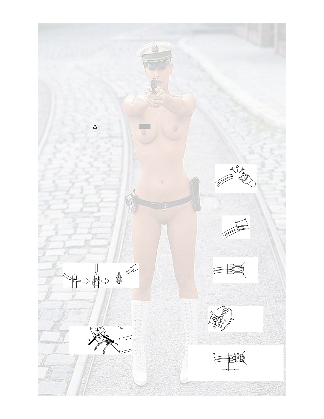
(6)Whenreplacing AC primarysidecomponents(transformers,
powercords,noiseblockingcapacitors,etc.) wrap endsof
wires securelyabout the terminalsbeforesoldering.
Fig.1-1-1
(7)Observe thatwiresdo notcontactheatproducing parts
(heatsinks,oxide metalfilmresistors,fusibleresistors,etc.)
(8)Checkthatreplaced wiresdo notcontactsharpedgedor
pointed parts.
(9)Whenapowercordhas beenreplaced,checkthat10-15
kgofforceinanydirectionwill not loosenit.
Fig.1-1-2
(10)Alsocheckareassurroundingrepairedlocations.
(11)Productsusingcathoderaytubes(CRTs)Inregardtosuch
products, thecathoderaytubesthemselves, thehighvolt-
agecircuits,and relatedcircuitsarespecifiedforcompli-
ancewithrecognizedcodespertainingtoX-rayemission.
Consequently, whenservicingtheseproducts,replacethe
cathoderaytubesand otherpartswithonlythespecified
parts.Undernocircumstancesattempt tomodifythesecir-
cuits.Unauthorizedmodificationcanincreasethe highvolt-
agevalueand causeX-ray emissionfromthecathoderay
tube.
(12)Crimptype wireconnectorInsuchcases aswhen replacing
thepowertransformerinsetswheretheconnectionsbe-
tweenthepowercordandpowertrans formerprimarylead
wiresareperformedusingcrimptypeconnectors, if replac-
ingthe connectorsisunavoidable,inordertopreventsafe-
tyhazards,performcarefullyandpreciselyaccordingtothe
followingsteps.
Connectorpart number :E03830-001
Requiredtool :Connectorcrimpingtooloftheproper
typewhichwill not damageinsulatedparts.
Replacementprocedure
a)Remove the oldconnectorbycuttingthewiresat a
pointclose totheconnector.Important:Donotre-
useaconnector (discardit).
Fig.1-1-3
b)Stripabout15mmoftheinsulationfromtheends
ofthe wires.Ifthewiresarestranded,twistthe
strands toavoidfrayed conductors.
Fig.1-1-4
c)Alignthelengthsofthewirestobeconnected.In-
sert the wiresfullyintothe connector.
Fig.1-1-5
d)AsshowninFig.1-1-6,usethecrimping tooltocrimp
themetalsleeveatthecenterposition.Besureto
crimpfullytothe completeclosureof the tool.
Fig.1-1-6
e)CheckthefourpointsnotedinFig.1-1-7.
Fig.1-1-7
б©»®½±®¼
½«¬ ½´±-»¬±½±²²»½¬±®
ïë ³³
ݱ²²»½¬±®
Ó»¬¿´-´»»ª»
Ý®·³°·²¹ ¬±±´
Ò±¬ »¿-·´§°«´´»¼º®»» Ý®·³°»¼¿¬¿°°®±¨ò½»²¬»
®
±º ³»¬¿´-´»»ª»
ݱ²¼«½¬±®-»¨¬»²¼»¼
É·®»·²-«´¿¬·±²®»½»--»¼
³±®»¬¸¿²ì³³

1-4(No.YD052)
1.1.2SafetyCheckafterServicing
Examinethe areasurroundingtherepaired locationfor damage
ordeterioration.Observethatscrews,partsandwireshavebeen
returnedtooriginalpositions,Afterwards,performthefollowing
testsandconfirmthespecifiedvaluesinordertoverifycompli-
ancewithsafetystandards.
(1)Insulationresistance test
Confirmthe specifiedinsulationresistanceorgreaterbe-
tweenpowercordplugprongsandexternallyexposed
partsoftheset(RFterminals,antennaterminals,videoand
audioinputandoutputterminals,microphonejacks,ear-
phonejacks, etc.).See table1below.
(2)Dielectricstrengthtest
Confirmspecifieddielectricstrengthorgreaterbetween
powercordplugprongsandexposedaccessiblepartsof
theset(RFterminals,antennaterminals,videoandaudio
inputandoutputterminals,microphonejacks,earphone
jacks, etc.). See Fig.1-1-11below.
(3)Clearancedistance
Whenreplacingprimarycircuit components, confirmspec-
ified clearancedistance(d), (d')betweensolderedtermi-
nals,andbetweenterminalsandsurrounding metallic
parts. SeeFig.1-1-11below.
Fig.1-1-8
(4)Leakagecurrenttest
Confirmspecifiedorlowerleakage currentbetween earth
ground/powercordplugprongsandexternallyexposed ac-
cessibleparts(RFterminals,antennaterminals,video and
audioinputandoutputterminals,microphonejacks,ear-
phonejacks, etc.).
MeasuringMethod:(PowerON)Insert load Zbetween
earthground/powercordplug prongsandexternallyex-
posedaccessibleparts.UseanACvoltmetertomeasure
acrossbothterminalsof loadZ.SeeFig.1-1-9andfollow-
ingFig.1-1-12.
Fig.1-1-9
(5)Grounding (Class1model only)
Confirmspecifiedor lowergroundingimpedancebetween
earthpininACinletandexternallyexposedaccessible
parts(Videoin,Videoout,Audioin,AudiooutorFixing
screwetc.).Measuring Method:
Connect milli ohmmeterbetweenearthpininACinletand
exposedaccessibleparts.SeeFig.1-1-10andgrounding
specifications.
Fig.1-1-10
Fig.1-1-11
Fig.1-1-12
NOTE:
Thesetablesareunofficial andfor reference only. Besuretoconfirmtheprecisevaluesfor yourparticular countryandlocality.
ݸ¿--·-
б©»®½±®¼
°®·³¿®§©·®»
¼ù
¼
¿¾
½
Ê
ß
Û¨¬»®²¿´´§
»¨°±-»¼
¿½½»--·¾´»°¿®¬
Æ
Û¨°±-»¼¿½½»--·¾´»°¿®¬
Ù®±«²¼·²¹ Ͱ»½·º·½¿¬·±²-
ßÝ·²´»¬
λ¹·±²
ËÍßú Ý¿²¿¼¿
Û«®±°» ú ß«-¬®¿´·¿
Ù®±«²¼·²¹ ׳°»¼¿²½» øÆ÷
Æðòﱸ³
Æðò뱸³
Û¿®¬¸°·²
Ó×´´· ±¸³³»¬»®
ßÝÔ·²»Ê±´¬¿¹» λ¹·±²
Ö¿°¿²
Û«®±°»ú ß«-¬®¿´·¿
ÎïÓñëððÊ ÜÝ
ËÍß ú Ý¿²¿¼¿ ïÓÎïîÓñëððÊ ÜÝ
ÎïðÓñëððÊ ÜÝ
ײ-«´¿¬·±²Î»-·-¬¿²½» øÎ÷Ü·»´»½¬®·½Í¬®»²¹¬¸ Ý´»¿®¿²½»Ü·-¬¿²½» ø¼÷ ôø¼ù÷
ïððÊ
ïðð¬±îìðÊ
ïï𠬱ïíðÊ
ïï𠬱ïíðÊ
îðð¬±îìðÊ
ßÝïµÊ ï³·²«¬»
ßÝïòëµÊ ï³·²«¬»
ßÝïµÊ ï³·²«¬»
øÝ´¿-- ÷
øÝ´¿-- ÷
ßÝíµÊ ï³·²«¬»
ßÝïòëµÊ ï³·²«¬»
¼ô ¼ùí³³
¼ô ¼ùì³³
¼ô ¼ùíòî³³
¼ùè³³ øÐ±©»®½±®¼÷
¼ùê³³ øÐ®·³¿®§©·®»÷
¼ì³³
ßÝÔ·²»Ê±´¬¿¹» λ¹·±²
Ö¿°¿²
Û«®±°»ú ß«-¬®¿´·¿
ËÍß ú Ý¿²¿¼¿
Ô±¿¼Æ Ô»¿µ¿¹»Ý«®®»²¬ø·÷ ¿ô ¾ô ½
ïððÊ
ïï𠬱ïíðÊ
ïï𠬱ïíðÊ
îîð¬±îìðÊ
·ï³ß®³-
·ðòë³ß®³-
·ðòé³ß °»¿µ
·î³ß¼½
·ðòé³ß °»¿µ
·î³ß¼½
Û¨°±-»¼ ¿½½»--·¾´»°¿®¬-
ß²¬»²²¿ »¿®¬¸¬»®³·²¿´-
Ѭ¸»®¬»®³·²¿´-
ï
ïòë
î
ëð
ðòïë

(No.YD052)1-5
1.2Preventingstaticelectricity
Electrostaticdischarge(ESD), whichoccurswhenstaticelectricitystored inthebody,fabric, etc.isdischarged,candestroy thelaser
diodeinthetraverseunit (optical pickup).Takecaretopreventthiswhen performingrepairs.
1.2.1Groundingtoprevent damagebystaticelectricity
Staticelectricityintheworkareacandestroy theoptical pickup(laserdiode)indevicessuchasDVDplayers.
Becarefultouseproper grounding inthe area whererepairsarebeingperformed.
(1)Groundthe workbench
Ground theworkbenchbylayingconductivematerial(suchasaconductivesheet)oranironplateoveritbeforeplacing the
traverseunit (optical pickup)onit.
(2)Groundyourself
Use an anti-staticwrist straptorelease anystaticelectricitybuiltupinyour body.
(3)Handlingtheopticalpickup
Inordertomaintainqualityduring transport andbeforeinstallation,bothsidesofthelaserdiode onthereplacementoptical
pickupareshorted. After replacement, returntheshorted partstotheiroriginal condition.
(Refer tothetext.)
Donotuseatestertochecktheconditionof thelaser diodeintheoptical pickup.Thetester'sinternalpowersourcecan easily
destroy thelaserdiode.

1-6(No.YD052)
1.3Precautions forService
1.3.1Handling of Traverse Unit and LaserPickup
(1)Donot touchany peripheral element of thepickup ortheactuator.
(2)Thetraverseunitandthepickup areprecisiondevicesandthereforemust not besubjectedtostrongshock.
(3)Donot use atestertoexamine the laser diode.(Thediode caneasilybedestroyedbytheinternalpowersupplyof thetester.)
(4)Toreplacethe traverseunit, pulloutthemetal short pinfor protection fromcharging.
(5)Whenreplacingthepickup,aftermountinganewpickup,remove the solderon theshort landwhichisprovidedatthecenterof
theflexiblewiretoopenthecircuit.
(6)Half-fixedresistorsforlaser poweradjustmentareadjustedinpairsatshipmenttomatch the characteristicsoftheopticalblock.
Donot changethesettingof thesehalf-fixedresistorsforlaserpoweradjustment.
1.3.2Destructionof TraverseUnitandLaserPickupbyStaticElectricity
Laserdiodesareeasilydestroyedbystaticelectricitychargedonclothingorthehumanbody.Beforerepairingperipheral elementsof
thetraverseunit or pickup,besuretotake thefollowingelectrostaticprotection:
(1)Wearanantistaticwristwrap.
(2)Withaconductivesheetorasteel plateontheworkbenchonwhichthetraverseunit or thepickupistobe repaired,ground the
sheetortheplate.
(3)It solderstotwoshortcircuit sectionsonthesubstrateof apick-up.
(4)Afterremovingtheflexiblewirefromtheconnector(CN101), short-circuit theflexiblewirebythe metalclip.
(5)Short-circuit thelaser diodebysolderingthe landwhichisprovidedat thecenter of theflexiblewirefor thepickup.
Aftercompletingtherepair, remove the soldertoopenthecircuit.
з½µó«°
͸±®¬½·®½«·¬
öд»¿-»®»º»® ¬±¬¸»ÍÛÝÌ×ÑÒíÜ×ÍßÍÍÛÓÞÔdz»¬¸±¼º±®¼»¬¿·´-ò
ÝÒïðï
ÜÊÜ ÍÛÎÊÑÝÑÒÌÎÑÔÞÑßÎÜ

(No.YD052)1-7
SECTION2
SPECIFICSERVICEINSTRUCTIONS
2.1Different tableof feature
The followingtableindicatesmaindifferentpointsbetweenmodelsHR-XVC28BUC,HR-XVC28BUS,HR-XVC29SUCandHR-
XVC29SUS.
NOTE:
Mark issameasleft.
2.2Serviceposition
Thisunit has beendesigned sothattheMechanismand Main
boardassemblies canberemovedtogetherfromthebottom
chassis.Beforediagnosingorservicingthecircuit boards,take
out themajor partsfromthebottomchassis.
2.2.1Howtosetthe"Serviceposition"
(1)Refertothedisassemblyprocedureandperformthedisas-
semblyof themajorpartsbeforeremovingtheMechanism
assembly.
(2)RemovethescrewsthatfixtheMechanism,Mainboardas-
semblytothe bottomchassis. If anyother screwsareused
tofixtheboards,remove themalso.
(3)Removethe combined Mechanismand Mainboardassem-
blies.
(4)If anyothermajorpartsareused,remove themalso.
(5)Connectthe wiresandconnectorsofthe majorpartsthat
havebeenremovedinsteps(1) to(4). (Refer toFig.2-2a.)
(6)Placethe combined Mechanism,Mainboardand other
boardassembliesupsidedown.
(7)Insertthepowercordplug intothe poweroutletandthen
proceedwiththediagnosticsand servicingof theboardas-
sembly.
Notes:
Beforeinsertingthepowercordplug intothepowerout-
let, makesurethatnoneofthe electricalpartsareable
toshort-circuitbetween theworkbench andtheboard
assembly.
Forthedisassemblyprocedureofthemajorpartsand
detailsoftheprecautionstobetaken,see"Removing
themajorparts".
IftherearewireconnectionsfromtheMainboardand
Mechanismassembliestotheothermajorparts,besure
toremovethem(includingwiresconnectedtothemajor
parts) first beforeperformingstep(2).
WhencarryingoutdiagnosisandrepairoftheMain
boardassemblyinthe"Serviceposition",besureto
ground boththe MainboardandMechanismassem-
blies.If theyareimproperlygrounded,theremaybe
noiseontheplaybackpictureorFDPcounterdisplay
maymoveevenwhenthe mechanismiskeptinaninop-
erative status.
Inordertodiagnose theplaybackorrecordingofthe
cassettetape,settheMechanismassemblytothere-
quiredmode beforeplacingit upsidedown.Ifthemech-
anismmodeischanged(includingejection)whileit isin
anupsidedownpositionthetapeinsidemay bedam-
aged.
Forsomemodels,the mechanismandboardassem-
blies areattached byconnectorsonly.Whencarrying
outadiagnosisorrepairoftheboardsinthe"Service
position",make surethatthe connectorsarenotdis-
connected.
Fig.2-2a
2.3JigRCUmode
Thisunitusesthe followingtwomodesforreceivingremotecon-
trol codes.
(1)UserRCUmode:Ordinarymode forusebytheuser.
(2)JigRCU mode: Modefor useinproductionandservicing.
WhenusingtheJigRCU,itisrequiredtoset theVCRtotheJig
RCUmode(themodeinwhichcodesfromthe JigRCUcanbe
received). Asbothofthe abovetwomodesarestoredinthe EE-
PROM, it isrequiredtosettheVCRbacktotheUser RCUmode
eachtimethat anadjustmentismadeor tocheckthattheneces-
saryoperationshavebeencompleted.These modescanbeset
bytheoperationsdescribed below.
Note:
ConfirmtheRCU modewhenexchangedparts.Since
someSERVICEPARTSsetstheVCRtotheJigRCU
modeas initial setting. ThereforepleasesettheVCRto
theuserRCU modeafterreplacingtheEEPROM.
HR-XVC28BUCHR-XVC28BUSHR-XVC29SUCHR-XVC29SUS
BODY COLORBLACK PURE SILVER
MP3PLAYBACKUSEDNOTUSEDUSEDNOTUSED
ÌÐïïï ÜòÚÚ
ÌÐìððïÝÌÔòÐ
ÌÐïðê ÐÞÚÓ
ÌÐîîëíßòÐÞ ÚÓ Ó¿·²¾±¿®¼¿--»³¾´§
Ü·-°´¿§¾±¿®¼¿--»³¾´§ Í©·¬½¸ñ¶¿½µ ¾±¿®¼¿--»³¾´§

1-8(No.YD052)
Fig.2-3aUser/JigRCUmode
2.3.1SettingtheJigRCUmode
(1)Turnonthepower.
(2)Pressthe followingremocon keyscontinuouslywithin2
seconds"SETUP" "2" "8" "ENTER".
WhentheVCRisset totheJigRCUmode, the symbols
(":") inthetimedisplayoftheFDPareturnedoff.
(Refer toFig.2-3a)
2.3.2SettingtheUserRCUmode
(1)Turnoffthepower.
(2)Pressthe"REC"and"PAUSE"buttons ofthe VCR simul-
taneously.Alternatively,transmit thecode"43-80"fromthe
JigRCU.
2.4Mechanismservicemode
Thismodelhasauniquefunction toenterthe mechanismintoev-
eryoperation modewithoutloadingofanycassettetape.This
functioniscalledthe"Mechanismservicemode".
2.4.1Howtosetthe"Mechanismservicemode"
(1)SettheVCRtotheJigRCUmode (themodeinwhich
codesfromtheJigRCUcan be received)
(2)Transmit thecode"43-E5"fromtheJigRCU.
(3)Releasethelug oftheCassetteholderandthenslidethe
CassetteholdertowardthedirectionwheretheCassette
holder isloadedbymanually.
(4)Thecassetteholderlowersand,whentheloadinghas
completed,themechanismentersthe desiredmode.
WhentheVCRissettotheMechanismservice mode, the
symbols("Timer")inthe FDP(LED)areblinked.
2.4.2Howtoexitfromthe"Mechanismservicemode"
(1)Unplugthe power cordplugfromthepower outlet.
2.5Maintenanceandinspection
2.5.1Cleaning
Regularcleaningofthetransport systempartsisdesirablebut
practicallyimpossible. Somake it aruletocarryoutcleaning of
thetape transportsystemwhenever themachineisserviced.
Whenthevideohead,tape guideand/orbrushgetsoiled,the
playbackpicturemay appearinferiororatworstdisappear,re-
sultinginpossibletape damage.
Note:
Absolutelyavoidsweepingthe upperdrumverticallyas
thiswillcausedamagetothevideohead.
(1)Whencleaningtheupperdrum(especiallythevideohead),
soak apiece of closelywovenclothwithalcohol and while
holdingtheclothontothe upperdrumbythe fingers,turn
theupper drumcounterclockwise.
(2)Tocleanthepartsofthetapetransport systemother than
theupperdrum,useapiece ofcloselywovenclothoracot-
tonswabsoakedwithalcohol.
(3)After cleaning,makesurethatthecleanedpartsarecom-
pletelydrybeforeusingthecassettetape.
Fig.2-5a
2.5.2Lubrication
Withnoneedforperiodicallubrication, youhaveonlytolubricate
newpartsafterreplacement.If anyoil orgrease on contactparts
issoiled, wipe it off and newlylubricatetheparts.
Note:
See the"mechanismassembly"diagramofthe"parts
list"forthelubricatingorgreasingspots,andforthe
typesof oil orgrease tobeused.
2.5.3Suggestedservicingscheduleformaincomponents
Thefollowingtableindicates thesuggestedperiodfor such ser-
vice measuresascleaning,lubricationand replacement. Inprac-
tice,theindicatedperiodswill varywidelyaccording to
environmentaland usageconditions.However, theindicated
componentsshouldbeinspectedwhenasetisbroughtforser-
vice and themaintenance workperformedifnecessary.Also
notethatrubberpartsmaydeformintime,evenif thesetisnot
used.
C: Cleaning
X: InspectionorReplacement ifnecessary
Ë-»® ÎÝË ³±¼»
Ö·¹ ÎÝË ³±¼»
ø²±¬¼·-°´¿§»¼÷
SystemPartsname Operationhours
1000H2000H
Tape
transport
DrumassemblyC,XX
A/CheadC,XC,X
Pinchroller armassemblyCC
Full erase headCC
TensionarmassemblyCC
Capstanmotor (Shaft)CC
GuidearmassemblyCC
Drive
CapstanmotorX
CapstanbrakeassemblyX
MainbrakeassemblyX
Belt (Capstan)XX
LoadingmotorX
ClutchunitX
WormgearX
ControlplateX
OtherRotaryencoderX
Ê·¼»±¸»¿¼-
ßñݸ»¿¼

(No.YD052)1-9
SECTION3
DISASSEMBLY
3.1Removingthemajorparts
3.1.1Destinationof connectors
Destinationofconnectors
3.1.2Howtoreadtheproceduretable
Thistableshowsthe stepsfor disassemblyof theexternallyfur-
nished partsandboardassemblies.Reversethese stepswhen
re-assemblingthem.
(1)Orderofsteps inProcedure
Whenreassembling, performthestep(s)inthe reverseor-
der.
Thesenumbersarealsousedastheidentification(loca-
tion)No. ofpartsFigures.
(2)Part nametoberemoved or installed.
(3)Fig. No. showingprocedureorpart location.
(4)Identificationofparttoberemoved,unhooked,unlocked,
released,unplugged, unclampedor unsoldered.
P=Spring,W=Washer, S=Screw,L=Lockingtab,SD=
Solder, CN**(WR**)=Removethewire(WR**)fromthe
connector (CN**).
Note:
Thebracketed ()WRoftheconnectorsymbol are
assignednos.inpriorityorderanddonotcorre-
spondtothose onthesparepartslist.
(5)Adjustmentinformationforinstallation
3.1.3Disassemblyprocedure
<Note2a>
Becarefulnottodamagetheconnectorandwireetc.during
connectionanddisconnection.
Whenconnectingtheflatwiretothe connector, be carefulwith
theflat wiredirection.
<Note2b>
WhenreattachingtheFrontpanelassembly,makesurethat
thedooropenerofthe Sideframe(R)islowered inposition pri-
ortothereinstallation.
When reattachingthe Frontpanelassembly,pay carefulattention
tothe switch leverofthe Frontpanelassemblynottomake it
touch the switchknob of the Mainboardassemblyfromtheside.
Whenreattachingthe Frontpanelassembly,lift theCassette
door slightly.
Fig.3-1a
<Note3a>
WhenreattachingtheMechanismassembly,securethe
screws(S3atoS3b)inthe orderof 1,2,3.
<Note3b>
Whenreattachingthe Mechanismassembly,besuretoalign
thephaseoftheRotaryencoderon theMainboardassembly.
WhenreattachingtheMechanismassembly,setthe"Mecha-
nismassemblingmode".[See"MECHANISMASSEMBLY
SERVICEMANUAL(No.86700)".]
Whenreattachingthe MechanismassemblytotheMainboard
assembly,take carenottodamagethesensorsand switchon
theMainboardassembly.
ÉÎî¿
ÉÎî¾
Ó¿·²ÝÒïðï
Ó¿·²ÝÒïðí
ìð
ïð
ÝÑÒÒò Ò±òÐ×ÒÒ±òÝÑÒÒÛÝÌÑÎ
æ ̸»½±²²»½¬±® ±º ¬¸»-·¼»¬±®»³±ª»
æ É·®»æ Ú´¿¬©·®»æÞ±¿®¼¬±¾±¿®¼øÞóÞ÷
Ü·¹·¬¿´ÝÒéêï
Ü·¹·¬¿´ÝÒéêî
ÝÑÒÒò Ò±òÐ×ÒÒ±òÝÑÒÒÛÝÌÑÎ
ÉÎî¿
ÉÎî¾
ÉÎí¿
ÉÎí¾
ÉÎì¿
ÉÎì¾
ÉÎì½
Ó¿·²
Ó¿·²
Ó¿·²
Ü®«³
¿--»³¾´§
Ó¿·²
Ó¿·²
Ó¿·²
ÝÒéïðí
ÝÒíïðî
ÝÒîððï
ÝÒéíðî
ÝÒéíðï
ÝÒííðï
Í©·¬½¸ñ¶¿½µ
Ü·-°´¿§
ßñݸ»¿¼
Ó¿·²
ÜÊÜ
-»®ª±½±²¬®±´
ÜÊÜ
-»®ª±½±²¬®±´
ÜÊÜ
-»®ª±½±²¬®±´
ÝÒéïçï
ÝÒéððí
ÝÒï
ÝÒëðí
ÝÒëðï
ÝÒï
ïð
îî
ê
ç
ïé
ïç
ë
øï÷øî÷øí÷øì÷øë÷
ͬ»°ñ
Ô±½Ò±ò
п®¬Ò¿³» Ú·¹ò
Ò±ò б·²¬Ò±¬»
ÅïÃ̱°½±ª»®íóï¿
ìøÍï¿÷ôøÍï¾÷ôíøÔï¿÷ôäÒ±¬»ï¿â
îøÍÜï¿÷ôøÐï¿÷ôøÉï¿÷ô
ÝÒïøÉÎï¿÷ô
Þ®¿½µ»¬îøÍï½÷
óóóóóóóóóóóóóóóóóóóóóóóóóóóóóóóóóóóóóóóó
ͬ»°ñ
Ô±½Ò±ò
п®¬Ò¿³» Ò±ò
Ú·¹ò б·²¬Ò±¬»
̱°½±ª»®
Ú®±²¬ °¿²»´¿--»³¾´§
øÜ·-°´¿§ ¾±¿®¼¿--»³¾´§÷
ø
Í©·¬½¸ñ¶¿½µ¾±¿®¼¿--»³¾´§
÷
Ó»½¸¿²·-³¿--»³¾´§
øÜ®«³¿--»³¾´§÷
ÜÊÜ«²·¬
øÞ®¿½µ»¬÷
λ¿®½±ª»®
Ó¿·²¾±¿®¼¿--»³¾´§
íóï¼
íóï¿
íóï¼
íóï¾
íóï½
íóï¼
íóï¼
íóï¼
íóï¼
èøÍï¿÷
ìøÔî¿÷ôëøÔî¾÷ôîøÍî¿÷
ÝÒéïðíøÉÎî¿÷ô
ÝÒíïðîøÉÎî¾÷
ÝÒîððïøÉÎí¿÷
íøÍí¿÷ôøÍí¾÷
ÝÒøÉÎí¾÷
øÍí½÷ôøÍí¼÷ôøÍí»÷
íøÍì¿÷ôíøÍì¾÷ô
ÝÒéíðîøÉÎì¿÷ô
ÝÒéíðïøÉÎìê÷ô
ÝÒííðïøÉÎì½÷
ëøÍë¿÷ôëøÔë¿÷
íøÍê¿÷
äÒ±¬»î¿â
äÒ±¬»î¾â
äÒ±¬»î¿â
äÒ±¬»í¿â
äÒ±¬»í¾â
äÒ±¬»í½â
óóóóóóóóóóóóóóóóóóóóóóóóóó
ÅïÃ
ÅîÃ
ÅíÃ
ÅìÃ
ÅëÃ
ÅêÃ
ܱ±®
±°»²»®
Í·¼»
º®¿³»øÎ÷ Í©·¬½¸
µ²±¾
Í©·¬½¸
´»ª»®

1-10(No.YD052)
<Note3c>
WhenreattachingtheDrumassembly,securethescrews(S3c
toS3e) intheorder of c, d,e.
Fig.3-1b
Whenhandlingthedrumassemblyalone, holditby the motor
or shaft. Becarefulnot totouchotherparts,especiallythevid-
eoheads.Alsotakecarenottodamage the connectors.
Fig.3-1c
äÒ±¬»í½â
øÍí½÷
øÍí½÷
øÍí»÷ øÍí»÷
øÍí¼÷
øÍí¼÷
Ó»½¸¿²·-³
¿--»³¾´§
Ü®«³
¿--»³¾´§
äÒÑÌÛâ
߬¬¿½¸¬¸» Ü®«³¿--»³¾´§¿°°®±°®·¿¬»´§ô
-·²½»¬¸» ·²-¬¿´´¿¬·±²-¬¿¬»±º ¬¸»Ü®«³¿--»³¾´§
·²º´«»²½»-¬¸» ÚÓÉßÊÛÚÑÎÓÔ×ÒÛßÎ×ÌÇ
¹®»¿¬´§ò
ØÑÑÕ
͸¿º¬
Ê·¼»± ¸»¿¼-
Ó±¬±®

(No.YD052)1-11
Fig.3-1d
øÔî¿÷
øÔî¿÷
øÔî¾÷
øÔî¾÷
øÔî¾÷
øÔî¾÷
øÍî¿÷
Ý¿--»¬¬»¼±±®
äÒ±¬»î¾â
ÅîÃÚ®±²¬ °¿²»´
¿--»³¾´§
»
¶
¾
¿
¿
½
·
·
·
·
·
º
¶
½
³
ÅíÃÓ»½¸¿²·-³
¿--»³¾´§
ÅíÃÜ®«³¿--»³¾´§
ÅêÃÓ¿·²¾±¿®¼¿--»³¾´§
Þ±¬¬±³½¸¿--·-
øÍí¿÷
øÍí¿÷
øÍí¾÷
øÍí»÷
øÍí½÷ øÍí¼÷
øÍê¿÷ øÍê¿÷
øÍê¿÷
øÍí¿÷
í
î
ÜÊܾ®¿½µ»¬
¾±¿®¼¿--»³¾´§
·
·
·
·
·
øÍë¿÷
øÍë¿÷
øÍë¿÷
øÔë¿÷
øÔë¿÷
øÔë¿÷
øÔë¿÷
øÔë¿÷
ÅëÃλ¿®½±ª»®
¼
¼
¼
¼
¼
½
»
¾
½
¶
º
¶
Ô
Ð
ö
ö
ö
ö
ö
ÅìÃÜÊÜ«²·¬
ÅìÃÞ®¿½µ»¬
øÍì¿÷
øÍì¿÷
øÍì¿÷
øÍì¾÷
øÍì¾÷
øÍì¾÷
ÅïÃ̱°½±ª»®
ï
øÍï¿÷
øÍï¿÷
øÍï¿÷
øÍï¿÷
øÍï¿÷
øÍï¿÷
¶
¶
¶
¶
ÌÑÐÍ×ÜÛ
ÞÑÌÌÑÓÍ×ÜÛ
Í©·¬½¸ñ¶¿½µ¾±¿®¼¿--»³¾´§
Ü·-°´¿§¾±¿®¼¿--»³¾´§
î
ï
íì
ïî
í
ì
ë
øÉÎî¾÷
äÒ±¬»î¿â
øÉÎî¿÷
äÒ±¬»î¿â
íòײ-»®¬¬¸»©·®»¬±»ª»²¬¸»®±±¬ ±º ½±²²»½¬±®½±³°´»¬»´§
¿¬ ¬¸» -¿³»¬·³»¿-·²-»®¬·²¹»¿½¸©·®»ò
ìòݸ»½µ¬±-»»¬¸¿¬±«¬-·¼»°¿®¬-ò
ÌÑÐÝÑÊÛÎôÞÑÌÌÑÓÝÑÊÛÎôÚÎÑÒÌÐßÒÛÔô »¬½
¿®»º·¨»¼½»®¬¿·²´§¬±¬¸»ÞÑÌÌÑÓÝØßÍÍ×Í
ëòп§¿¬¬»²¬·±²ÒÑ̬±³¿µ»¿²§-½®¿¬½¸»-
±²ÚÎÑÒÌÐßÒÛÔò
êòп§½´±-»¿¬¬»²¬·±²²±¬¬±½«¬ ¿²§
͸»¿¬¸±ºÉ×ÎÛ ¾§-¸¿®°»¼¹»
±ºÝØßÍÍ×Í ©¸·´»É·®»·²¹Ð®±½»--ò
º®±³ÚÎÑÒÌÐßÒÛÔ
øÖßÝÕÝÒéïçï÷
ßñÝØÛßÜ
ÝÒîððï
ÝÒíïðî
ÝÒéíðî ÝÒéíðï
ÝÒííðï
ÝÒëðí ÝÒëðï
¾¿½µ-·¼»
®·¹¸¬ -·¼»
ÝÒï
øÉÎì¿÷
äÒ±¬»î¾â
øÉÎì½÷
äÒ±¬»î¾â
øÉÎí¿÷
äÒ±¬»î¾â
øÉÎí¿÷
äÒ±¬»î¾â
øÉÎí¾÷
äÒ±¬»î¾â
øÉÎì¾÷
äÒ±¬»î¾â
Ó¿µ»¿½®»¿-»ò
äи¿-»¿´·¹²³»²¬â
òß½½±®¼ ¬¸» °±-·¬·±² ±ºÊ¹¿° ±² ÎòÛÒÝÑÎÜÛÎ ¿²¼ ÐÉÞ-·´µ
òß½½±®¼ ¬¸» °±-·¬·±² ±ºÞ±-- ±²ÎòÛÒÝÑÎÜÛο²¼ÐÉÞ-·´µ
ÖÍíððï
îò ÚÚÝÉ×ÎÛ¿²¼ÜÎËÓÚÐÝÉ×ÎÛ
-¸±«´¼¾»·²-»®¬¿-º±´´±©-ò
ïò ײ-»®¬¼·®»½¬·±²±ºÚÚÝÉ×ÎÛ ¿-º±´´±©-ò
ÝÒ
»´»½¬®±¼»-·¼»
çð
ÑÕ
®·¹¸¬ -·¼»
ÝÒ ÝÒ
-«°°±®¬·²¹ -·¼»
ÒÙ
¾¿½µ-·¼»
ÒÑÌÛ
ÝÒíïðî
ÒÑÌÛ÷ÚÚÝÉ×ÎÛÍØÑËÔÜÞÛÐÑÍ×Ì×ÑÒÛÜ
ÞÛÔÔÑÉÝßÍÍÛÌÌÛÜÑÑÎò
øÚÑÎßÊÑ×ÜÚÚÝÉ×ÎÛ
Ü×ÍÌËÎÞÝßÍÍÛÌÌÛ×ÒßÒÜÑËÌò÷
ײ-»®¬¬¸»¾«-¸·²¹ ±ºÐÑÉÛÎÝÑÎÜ -±¿-²±¬¬±¬©·-¬ ¬¸»½±®¼ò

1-12(No.YD052)
3.2Loadingmechanismassembly
3.2.1Removing thetray (SeeFigure3-2a,Figure3-2b,Figure3-2c, Figure3-2d,Figure3-2e, Figure3-2f)
(1)Push aof theslidecamontheholeintherightsideof the
loadingbase byusingadriveruntil it stops. (SeeFigure3-
2a.)
(2)Thetraycomesout. Pullthe tray inafront direction until it
stops.
(3)Removethetwoscrews Aattachingtheslide bracket. (See
Figure3-2b.)
(4)Tilt the trayinadirectionofthearrowaround the pointin
theleft rearpart of the tray.(SeeFigure3-2c.)
(5)Therailof thetray isremovedfrom bofthe loadingbase.
Then,remove thetrayupward. (SeeFigure3-2d.)
Attaching thetray:
Engage coftheloadingbasetotheprojectionofthe traywhile
tiltingthetray totheleft. Turnthetray inadirection ofthear-
row,andattachtheslidebracket.(See Figure3-2e.)
Note:
Priortothe procedureabove,movetheslide caminadirection
ofthearrowsothat dof the slide camcanbeinsertedin eof
thetray. (See Figure3-2f.)
Fig.3-2a
Fig.3-2b
Fig.3-2c
Fig.3-2d
Fig.3-2e
Fig.3-2f
Ì®¿§
Ы-¸
Ô±¿¼·²¹ ¾¿-»
Í´·¼»½¿³°¿®¬ ¿
Ì®¿§
ß ß
Í´·¼»¾®¿½µ»¬
Ì®¿§
̸»°±·²¬ ·²¬¸»´»º¬ ®»¿® °¿®¬
Ô±¿¼·²¹ ¾¿-»°¿®¬ ¾Î¿·´ ±º ¬¸»¬®¿§
Ю±¶»½¬·±²±º ¬¸»¬®¿§
Ô±¿¼·²¹ ¾¿-»°¿®¬ ½
Í´·¼»½¿³
ﮬ ¼
ﮬ »

(No.YD052)1-13
3.2.2Removingthetraversemechanismassembly(SeeFigure3-2g)
Reversetheloadingmechanismassembly.Removethefour
screws Battachingthetraversemechanismassembly.Remove
thetraversemechanismassemblyupward.
Fig.3-2g
3.2.3Removingtheelevator(SeeFigure3-2handFigure3-2j)
Priortothefollowingprocedure,removethe traversemecha-
nismassembly.
(1)Removethe twoarmsoftheelevatorfromthetwoparts f
bymoving thearmsinadirection of the arrow.
(2)Pull out the elevatorinareardirection.
Attachingtheelevator:
Engagethetwoholes gtothetwoshaftsonthe frontpartof
theelevator. Andthen,attachthe elevator.
Fig.3-2h
Fig.3-2j
Ô±¿¼·²¹ ³»½¸¿²·-³¿--»³¾´§
Þ
Þ
Þ
Þ
Ì®¿ª»®-»³»½¸¿²·-³¿--»³¾´§
ﮬ ºÐ¿®¬
º
Û´»ª¿¬±®
Í´·¼»½¿³ ¹
¹
͸¿º¬
Û´»ª¿¬±®

1-14(No.YD052)
3.2.4Removingtheloadingmotor(SeeFigure3-2kandFigure3-2l)
Prior tothe followingprocedure, removethetray, thetraverse
mechanismassembly,andthe elevator.
(1)Removethebelt fromthe pulley.
(2)Removetwoscrews Cattachingtheloadingmotor.
(3)Removetwosolders hontheswitchboard.
Fig.3-2k
Fig.3-2l
3.3Traversemechanismassembly
3.3.1Removingthepickup (See Figure3-3a,Figure3-3b)
Priortothefollowingprocedure,removethetraversemecha-
nismassembly.
(1)Removeonescrew Dattachingthe plate.
(2)Removetheplateandthe leafspring.
(3)Lift iof theshaft 1,andpull out the shaft 1from j.
(4)Remove kof thepickupfromtheshaft 2.
Attachingthepickup:
(1)Engage kof thepickup tothe shaft 2.
(2)Inserttheshaft 1in j, and attachtheshaft 1to i.
(3)Attachthe leaf spring,andthenattach theplate. Fixthe
leafspringandtheplatebyusingthescrew D.
Fig.3-3a
Fig.3-3b
Ô±¿¼·²¹ ¾¿-»
Í´·¼»½¿³
Þ»´¬
Ý
Ý
Ы´´»§ Ы´´»§
Ô±¿¼·²¹ ³±¬±®
Í©·¬½¸¾±¿®¼ ﮬ ¸
Ü
д¿¬»
Ô»¿º-°®·²¹
ﮬ ·
͸¿º¬ï
͸¿º¬î ﮬ µ
ﮬ ¶

(No.YD052)1-15
SECTION4
ADJUSTMENT
4.1Beforeadjustment
4.1.1Precaution
Theadjustmentsofthisunit include themechanismcom-
patibilityand electricaladjustments.During the perfor-
manceofthiswork,besuretoobserve theprecautionsfor
each typeof adjustment.
Ifthereisareferencetoasignalinputmethod inthesignal
columnof theadjustmentchart, "Ext. S-input"meansthe
Y/Cseparatedvideosignaland"Ext.input" meansthe
compositevideosignal input.
Unless otherwisespecified, all measuring pointsand
adjustment partsarelocatedontheMainboard.
4.1.2Requiredtest equipments
Color(colour) televisionormonitor
Oscilloscope:wide-band, dual-trace, triggereddelayedsweep
Signal generator: RF/ IFsweep/marker
Signal generator: stairstep,color (colour) bar [NTSC]
Recording tape
Digit-keyremotecontroller(provided)
4.1.3Requiredadjustmenttools
: Used--- : Not used
4.1.4Color(colour) barsignal,Color(colour) barpattern
4.1.5Switch settings
Whenadjusting thisunit, settheVCRmode andswitches
asdescribedbelow.
Whenusing the JigRCU,it isrequiredtosettheVCRtothe
JigRCUmode(themode inwhichcodes fromtheJigRCUcan
bereceived).(See "section 2SPECIFICSERVICEINSTRUC-
TIONS".)
Fig.4-1JigRCU [PTU94023B]
Settheswitches asshownbelowunlessotherwisespecified
ontherelevantadjustmentchart.Theswitchesthatarenotlist-
edbelowcanbesetas desired.
If theVCRisnotequippedwiththe functionsdetailedbelow,
setupisnotrequired.
4.1.6Manualtrackingmode(AutotrackingON/OFF)set-
ting
(1)Inordertosettothemanualtrackingmodeduring tape
playback,pressthe"TRACKING+and-"buttonatthe
sametimeonthe remotecontrol unit.
Each press of the buttonswitchestheautotracking ON
orOFF.
Whenthemanualtrackingmodeisset, thetrackingis
placedat thecenterposition.
(2)Press"TRACKING +/-"toadjust the tracking manually.
Mechanism
compatibility
adjustment
Electrical
adjustment
Rollerdriver ---
JigRCU ---
Back tension cassettegauge ---
Alignmenttape(MHP) ---
Alignmenttape(MHP-L)
α´´»®¼®·ª»®
ÐÌËçìððî
Þ¿½µ¬»²-·±²½¿--»¬¬»¹¿«¹»
ÐËÖìèðéêóî
Ö·¹ ÎÝË
ÐÌËçìðîíÞ
ß´·¹²³»²¬ ¬¿°»
øÍÐô-¬¿·®-¬»°ôÒÌÍÝ÷
ÓØÐ
ß´·¹²³»²¬ ¬¿°»
øÛÐô-¬¿·®-¬»°ôÒÌÍÝ÷
ÓØÐóÔ
ÜÊÜ ¬»-¬ ¼·-½
ÊÌóëðï
ÝÜóÜ߬»-¬ ¼·-½
ÝÌÍóïððð
AUTOPICTURE/VIDEOCALIBRATION/
B.E.S.T./D.S.P.C.
OFF
PICTURECONTROL/SMARTPICTURENORMAL/NATURAL
VIDEOSTABILIZEROFF
TBCON
Digital3RON
VIDEONAVIGATION/TAPE MANAGEROFF
BLUE BACKOFF
ɸ·¬»øéëû÷
ïðð×ÎÛ
ìð×ÎÛ
ر®·¦±²¬¿´ -§²½
Ï×
ïÊ
ɸ·¬»øïððû÷
Ç»´´±©
ݧ¿²
Ù®»»²
Ó¿¹»²¬¿
λ¼
Þ´«»
Þ«®-¬
ìð×ÎÛ
ɸ·¬»
Ç»´´±©
ݧ¿²
Ù®»»²
Ó¿¹»²¬¿
λ¼
Þ´«»
Ï×Þ´¿½µ
ɸ·¬»
ïððû
øéëû÷
ݱ´±®ø½±´±«®÷¾¿®-·¹²¿´ÅÒÌÍÝà ݱ´±®ø½±´±«®÷¾¿®°¿¬¬»®²ÅÒÌÍÝÃ
×Ò×Ì×ßÔÓÑÜÛ
ÜßÌßÝÑÜÛ
ÝËÍÌÑÓÝÑÜÛ
ìíæßÝÑÜÛ
ÅÜ¿¬¿¬®¿²-³·¬¬·²¹ ³»¬¸±¼Ã
Ü»°®»-- ¬¸» þþøí÷¾«¬¬±²
¿º¬»®¬¸»¼¿¬¿½±¼» ·--»¬ò
Ö·¹ÎÝË

1-16(No.YD052)
4.2Mechanismcompatibilityadjustment (VHSSECTION)
Notes:
Although compatibilityadjustmentisveryimportant, it
isnotnecessarytoperformthisaspartofthe normal
servicingwork.It willberequiredwhen youhavere-
placedthe A/Chead,drumassemblyoranypart ofthe
tapetransport system.
Topreventdamagingthealignmenttape inthecompat-
ibilityadjustment, prepareacassettetape(forself-re-
cording/playback), performatestonit bytransporting it
andmakingsurethatthetapeisnotbentbythetape
transport mechanismssuch asintheguiderollers.(See
Fig.4-2b.)
4.2.1Tensionpoleposition
Notes:
Thisadjustment mustbeperformedeverytimetheten-
sion bandisreplaced.
(1)Play backthebacktensioncassettegauge(A).
(2)Checkthattheindicatedvalueontheleft sidegaugeis
withinthespecifiedvalue(G).
(3)If theindicated valueisnotwithinthe specifiedvalue (G),
performtheadjustmentinafollowingprocedure.(See
Fig.4-2a.)
a)Removethe topframe,cassetteholderandside
frames (L/R)all together.(RefertotheSERVICE
MANUALNo.86700[MECHANISMASSEMBLY].)
b)Rotatetheloadingmotorgeartomovethe control
platesothat thetriangular stamping totheleft of the
!P"stampingisalignedwiththestamping(a)onthe
maindeck.Thispositioningismode(B1).
c)Adjustbyturningtheadjustmentpinso thatthetipof
thetension armisalignedwiththe stamping(b)on
themaindeck.
d)Rotatethe reeldisk(S)byaboutone turnclockwise
andmakesurethat theroundholeoftheadjustment
pinislocatedinthe"OK"range.If it isoutside this
range, restarttheadjustmentfromthebeginning.
After completionof the adjustment,rotatetheloadinggear
motor toreturnittothemode(B2)position.
Fig.4-2a
4.2.2FMwaveformlinearity
(1)Play backthealignment tape (A1).
(2)Applytheexternal trigger signal toD.FF(E), toobserve
theV.PBFMwaveformatthemeasuringpoint (D).
(3)Set the VCRtothemanual trackingmode.
(4)MakesurethatthereisnosignificantleveldropoftheV.PB
FMwaveformcausedbythe tracking operation,withits
generallyparallelandlinearvariation ensured. Performthe
followingadjustmentswhenrequired. (SeeFig.4-2c.)
(5)ReducetheV.PBFMwaveformby thetrackingoperation.
If adrop inlevel isfoundon theleft side, turntheguideroll-
erofthepolebase assembly(supplyside)withtheroller
driver tomaketheV.PBFMwaveformlinear.
Ifadropinlevelison therightside,likewiseturntheguide
rollerofthepolebaseassembly(take-upside)withthe
rollerdrivertomake it linear. (SeeFig.4-2c.)
(6)MakesurethattheV.PBFMwaveformvariesinparallel
andlinearlywiththetrackingoperationagain.Whenre-
quired, performfine-adjustmentoftheguiderollerofthe
polebaseassembly(supplyortake-upside).
(7)Unloadthe cassettetapeonce, play backthealignment
tape (A1) againand confirmtheV.PBFMwaveform.
(8)Afteradjustment, confirmthatthetapewrinklingdoesnot
occurattherollerupperorlowerlimits.(SeeFig.4-2b.)
[Performadjustmentstep(9)onlyforthemodelsequipped
withSPmodeandEP(or LP)mode.]
[Performadjustmentstep(9)onlyforthemodels
equipped withSPmodeandEP(orLP)mode.]
(9)Repeat steps(1) to(8)by usingthe alignment tape(A2).
Fig.4-2b
Signal(A) Back tensioncassettegauge[PUJ48076-2]
Mode(B1)
(B2)
PB
Eject end
Adjustmentpart(F) Adjustpin[Mechansim assembly]
Specifiedvalue(G) 25-51gf cm(2.45-5x10⁻³ Nm)
ÑÕ
ÒÙ
ßÜÖËÍÌÐ×Ò
ÌÛÒÍ×ÑÒ ßÎÓ
ͬ¿³°·²¹ø¾÷
ͬ¿³°·²¹ø¿÷
ÝÑÒÌÎÑÔÐÔßÌÛ
Signal(A1)
(A2)
Alignmenttape(SP,stairstep,NTSC)[MHP]
Alignmenttape(EP,stairstep,NTSC)[MHP-L]
Mode(B) PB
Equipment(C) Oscilloscope
Measuringpoint(D) TP106 (PB. FM)
Externaltrigger(E) TP111(D.FF)
Adjustmentpart(F) Guideroller[Mechanismassembly]
Specifiedvalue(G) FlatV.PB FMwaveform
Adjustmenttool(H) Rollerdriver[PTU94002]
ø¿÷ ÙË×ÜÛ ÎÑÔÔÛÎ
ø¾÷
ÙË×ÜÛ ÐÑÔÛ
׳°®±°»® Ю±°»®

(No.YD052)1-17
Fig.4-2c
4.2.3Heightandtilt of the A/Chead
Note:
SetatemporaryleveloftheheightoftheA/Cheadinad-
vancetomaketheadjustmenteasieraftertheA/Chead
hasbeenreplaced.(RefertotheSERVICEMANUAL
No.86700[MECHANISMASSEMBLY].)
(1)Playbackthealignmenttape(A).
(2)Applytheexternal triggersignaltoD.FF (E), toobservethe
AUDIOOUTwaveformandControl pulsewaveformat the
measuring points(D1)and(D2)intheALTmode.
(3)Set theVCRtothemanualtracking mode.
(4)Adjustthe AUDIOOUTwaveformandControlpulsewave-
formbyturningthescrews(1), (2)and (3) littlebylittleuntil
bothwaveformsreachmaximum. Thescrew(1)
and(3)areforadjustmentoftiltandthescrew(2)forazi-
muth.
Fig.4-2d
4.2.4A/Cheadphase (X-value)
(1)Playbackthealignmenttape(A1).
(2)Applytheexternal triggersignaltoD.FF (E), toobservethe
V.PBFMwaveformat themeasuringpoint(D).
(3)Set theVCRtothemanualtracking mode.
(4)Loosenthescrews(4)and(5),then setthe Rollerdriverto
theinnermostprojectedpartofthe A/Chead. (SeeFig.4-
2e.)
(5)RotatetherollerdriversothattheA/Cheadcomesclosest
tothe capstan.Fromthere,move theA/Cheadbackgrad-
uallytowardthedrumuntilthepointwheretheFMwave-
formismaximizedforthesecondtime, andthen
tightenthe screws(4) and (5)temporarily.
(6)Playanalignment tape(A2) andsettothemanual-tracking
mode.
(7)Fine-adjustA/Cheadbaseposition tomaximize theFM
waveform,andthentightenthescrews(4)and(5) firmly.
(8)Playalignmenttapes (A1)and (A2)and confirmthattheFM
waveformsaremaximizedwhen thetrackingisatthecen-
ter position.
Fig.4-2e
Fig.4-2f
Signal(A) Alignmenttape(SP,stairstep, NTSC)[MHP]
Mode(B) PB
Equipment(C) Oscilloscope
Measuringpoint(D1)
(D2)
TP106(PB.FM)
TP4001(CTL. P)
Externaltrigger(E) TP111(D.FF)
Adjustment part(F) A/Chead[Mechanismassembly]
Specifiedvalue(G) Maximumwaveform
׳°®±°»®©¿ª»º±®³ª¿®·¿¬·±²
ß
Þ
Ý Ü
˰ܱ©²
Ù«·¼»®±´´»®
ø-«°°´§-·¼»÷
α´´»®¼®·ª»®
Ю±°»®©¿ª»º±®³ª¿®·¿¬·±²
Ø»¿¼¾¿-»
ßñݸ»¿¼
ßËÜ×ÑÑËÌ
ÝÌÔòÐ
øï÷
øî÷
øí÷
Signal(A1)
(A2)
Alignmenttape(SP,stairstep, NTSC)[MHP]
Alignmenttape(EP,stairstep,NTSC)[MHP-L]
Mode(B) PB
Equipment(C) Oscilloscope
Measuringpoint(D) TP106(PB. FM)
Externaltrigger(E) TP111(D.FF)
Adjustment part(F) A/Cheadbase[Mechanismassembly]
Specifiedvalue(G) FlatV.PBFMwaveform
Adjustment tool(H) Rollerdriver[PTU94002]
Ø»¿¼¾¿-»
α´´»®¼®·ª»®
̱¬¸»½¿°-¬¿²
̱¬¸»¼®«³
̱©¿®¼¬¸»½¿°-¬¿²
̱©¿®¼¬¸»¼®«³
ͽ®»©øë÷
ͽ®»©øì÷
ßñݸ»¿¼
ß´·¹²³»²¬¬¿°»
ÅÍÐô-¬¿·®-¬»°Ã
°´¿§»¼ ©·¬¸¬¸»
ÍÐ ¸»¿¼
ß´·¹²³»²¬¬¿°»
ÅÛÐøÔÐ÷ô-¬¿·®-¬»°Ã
°´¿§»¼ ©·¬¸¬¸»
ÛÐøÔÐ÷¸»¿¼
Ü®«³-·¼»Ý±²¬®±´¸»¿¼°±-·¬·±²Ý¿°-¬¿²-·¼»
È󪿴«» ¿¼¶«-¬³»²¬ °±·²¬
Ó¿¨·³«³

1-18(No.YD052)
4.3Electricaladjustment(VHSSECTION)
Note:
Thefollowing adjustmentproceduresarenotonlynecessary
afterreplacementofconsumablemechanicalpartsorboard
assemblies,butarealsoprovidedasreferencestobereferred
towhenservicingtheelectrical circuitry.
Incaseoftroublewiththeelectricalcircuitry,alwaysbegina
service byidentifying thedefectivepointsbyusingthemeasur-
inginstrumentsas describedinthe followingelectricaladjust-
mentprocedures.Afterthis,proceedtotherepair,
replacementand/oradjustment.Iftherequiredmeasuringin-
strumentsarenot availableinthefield,donot change thead-
justment parts(variableresistor, etc.) carelessly.
4.3.1Servocircuit
4.3.1.1Switchingpoint
(1)Play backthe signal (A1) ofthealignmenttape(A2).
(2)Applythe externaltriggersignaltoD.FF(E) toobserve the
VIDEOOUTwaveformandV.PBFMwaveformat the
measuringpoints(D1)and(D2).
(3)Set theVCRtothemanualtrackingmode.
(4)Adjust trackingsothat theV.PBFMwaveformbecomes
maximum.
(5)SettheVCRtotheAutoadjustmodebytransmittingthe
code(F) fromtheJigRCU. When theVCRentersthestop
mode, theadjustmentiscompleted.
(6)If theVCRenterstheejectmode, repeat steps(1) to(5)
again.
(7)Play backthealignment tape (A2)again,confirmthat the
switchingpointisthespecifiedvalue(G).
Fig.4-3aSwitchingpoint
4.3.1.2Slowtracking preset
(1)Recordthe signal(A2) inthe mode (B1),andplay back
therecordedsignal.
(2)Set the VCRtothemanual trackingmode.
(3)Set theVCRtotheFWDslow(+1/6x) mode.
(4)Transmitthe code(F)fromtheJigRCUtoadjustsothatthe
noisebar becomes thespecifiedvalue(G) ontheTV
monitorinthe slowmode.
(5)Set the VCRtotheStopmode.
(6)Confirmthatthenoisebaris(G)ontheTVmonitorinthe
slowmode.
(7)Repeat steps(3) to(6) intheREVslow(+1/6x) mode.
(8)Repeat steps(1) to(7) inthemode(B2).
Note:
ForFWDslow(+1/6x)playback,transmitthecode"43-
08"fromtheJigRCUtoentertheslowplaybackmode,
andtransmitthecode"43-D0"forREV slow(-1/6x)
mode.
Signal(A1)
(A2)
Stairstepsignal
Alignmenttape(EP,stairstep,NTSC)[MHP-L]
Mode(B) PB
Equipment(C) Oscilloscope
Measuring point(D) VIDEOOUTterminal(75ohmterminated)
TP106 (PB. FM)
Externaltrigger(E) TP111(D.FF)
Adjustmentpart(F) JigRCU:Code !43-5A"
Specifiedvalue(G) 6.5±0.5H
Adjustmenttool(H) JigRCU [PTU94023B]
Êò-§²½
Ì®·¹¹»®°±·²¬
Í©·¬½¸·²¹°±·²¬
Êò ®¿¬»
Signal(A1)
(A2)
Ext. input
Color(colour)barsignal[NTSC]
Mode(B1)
(B2)
VHSSP
VHSEP
Measuringpoint(D) TV-Monitor
Adjustmentpart(F) JigRCU:Code !43-71"or !43-72"
Specifiedvalue(G) minimumnoise
Adjustmenttool(H) JigRCU [PTU94023B]

(No.YD052)1-19
4.4Electricaladjustment(DVD SECTION)
4.4.1Testmodesettingmethod
(1)PressPOWERbuttontoturnoff theunit.
(2)Pressthefollowingremoconkeyscontinuouslywithin2seconds"SETUP" "2" "8" "ENTER".
(3)TheunitbecomesJIGRCUmode.
(4)PressPOWERbuttonthenpressVCR/DVDrepeatedlysothat theDVDindicator lightsuponthefront display panel.
(5)PressthePOWERbuttonagaintoturnoff theunit.
(6)Transmitthecode"43-FA "fromthe JigRCU.
(7)Thepowersupplyoftheunit turnsonautomaticallythentheFDPshowsthe regionnumber.
(8)Each pressing of DISPLAYbuttonoftheremotecontrollerintest modeasfollows.
(9)Toreleasetest mode, pressPOWERkey ofthe front panel.
4.4.2Methodofdisplayedversionof firmware
(1)Set theunit tothe test mode.
(2)Theversionnumberisdisplayed inthe monitor screen.
ÚÜÐøÛ¨¿³°´»÷
Þ»½¿³»-¬»-¬ ³±¼»
øÎ»¹·±²²«³¾»®÷
Ѱ¬·³·¦»Ú®±²¬Û²¼ °¿®¿³»¬»
®
ÝÜ Ô¿-»®
ÜÊÜÔ¿-»®
ÊÝÎ
ÑÐÛÒ×ÒÙÜ×ÍÐÔßÇ
ööÁÊ»®òööööÁØÍñØÎÁÈÊÝîçñööööööö
Ü»-¬·²¿¬·±²
Ê»®-·±²±ºº·®³©¿®»
Ó±¼»´²¿³»
Ѭ¸»®-

1-20(No.YD052)
4.4.3Initialization method
Pleaseinitializeaccordingtothe followingproceduresinthefollowingcase:
Just after youupgradethefirmware.
Afteryou confirmthesymptomsthat acustomer pointsout. FirstInitialize,and thenconfirmwhetherthe symptomsareimproved or
not.
After servicing, beforereturningthe mainbodytoacustomer. (Initializedunit shouldbe returned toacustomer.)
(1)Set theunittothetest mode.
(2)PressPAUSEkeyoftheremotecontrollerortransmitthecode"43-6F"fromtheJigRCU.
(3)Wheninitializationiscompleted, thePLAY( ).markisindicated intheFDP.
4.4.4All-initialization method
Pleaseperformall-initialization accordingtothefollowingproceduresinthefollowingcase:
Just after youexchangethepick-up.
Just after youexchange thespindlemotor.
Just after you exchangethetraversemechanismbase.
NOTE:
Pleaseperformall-initializationwhen youexchange the partsaboveandalsowhen youremovethepartsabove.
(1)Set theunittothetest mode.
(2)PresstheREVERSESKIP/INDEX( ) keyoftheremotecontrollerformorethan2seconds.
(3)Wheninitializationiscompleted, thePLAY( ).markisindicated intheFDP.
NOTE:
Afterall-initialization, besuretoperformoptimization adjustment ofFront Endparameter.
4.4.5OptimizationadjustmentofFrontEndparameter
AdjustmenttooptimizeFrontEndparametermustbeperformedineach mechanismassemblyofthismodelforhigh-speedstart-
ing.Please performoptimizationaccordingtothefollowingproceduresjustafterall-initializationiscompletedand whenFDPshows
anythingexcept "0" (For examplewhenFDPshows"1", "2", and "3") at testmode.
(1)Set theunit tothetest mode.
(2)TheFDPshowsthe regionnumber first.
(3)PresstheDISPLAYkeyoftheremotecontrollerandcheckthatFDP showsthenumber.
(4)PresstheDISPLAY keyagaintoreturntheregionnumber.
NOTE:
Statusof thisadjustment canbejudgedbythe number displayed at testmode asfollows:
NOTE:
Asfor adiscused for adjustment,
Discshouldbemounted.("Mounting"meanstodisplay"READ"after the disc isinserted andthendisplaythediscinforma-
tion.) Discneed not beplayed.
If youdonothavetestdisc eitherVT-501 (DVD) orCTS-1000(CD-DA),useacommercialdisc(forDVD,dual-layersoft-
ware)afterseeingandcheckingthatthediscisneithercurved norforeseenthatit mayshakeatthetimeofplayback.If you
useadiscwithbad features,startingtimemaybeslowordiscmaynotberead.
DVDadjustmentCDadjustmentFDPat testmode
AdjustedAdjusted0
Not adjustedAdjusted1
AdjustedNot adjusted2
Not adjustedNot adjusted3
Other manuals for HR-XVC28BUS
1
This manual suits for next models
2
Table of contents
Other JVC DVD Player manuals

JVC
JVC XV-N35SL User manual

JVC
JVC XV-F80BK - Progressive-Scan DVD Player User manual

JVC
JVC XV-MK5GSL User manual

JVC
JVC XV-N55SL Quick start guide

JVC
JVC XV-S40BK User manual

JVC
JVC XVN412S - Progressive-Scan DVD Player User manual

JVC
JVC XV-S300BK User manual

JVC
JVC XV-D721BK User manual
![JVC XV-N30BK[MK2] User manual JVC XV-N30BK[MK2] User manual](/data/manuals/21/0/210j3/sources/jvc-xv-n30bk-mk2--manual.jpg)
JVC
JVC XV-N30BK[MK2] User manual

JVC
JVC HR-XV1EU-R User manual