JVC RX-F31S User manual

English
LVT1306-009B
[US]
RX-F31S
INSTRUCTIONS
HOME CINEMA CONTROL CENTER
cover_RX-F31S[US]ff.p65 05.6.9, 17:013

G-1
RX-F31S
Warnings, Cautions, and Others /
Caution–– STANDBY/ON button!
Disconnect the mains plug to shut the power off completely.
The STANDBY/ON button in any position does not
disconnect the mains line. The power can be remote controlled.
CAUTION
To reduce the risk of electrical shocks, fire, etc.:
1. Do not remove screws, covers or cabinet.
2. Do not expose this appliance to rain or moisture.
CAUTION
•Do not block the ventilation openings or holes.
(If the ventilation openings or holes are blocked by a newspaper
or cloth, etc., the heat may not be able to get out.)
•Do not place any naked flame sources, such as lighted
candles, on the apparatus.
•When discarding batteries, environmental problems must be
considered and local rules or laws governing the disposal of
these batteries must be followed strictly.
•Do not expose this apparatus to rain, moisture, dripping or
splashing and that no objects filled with liquids such as
vases, shall be placed on the apparatus.
Caution: Proper Ventilation
To avoid risk of electric shock and fire and to protect from damage.
Locate the apparatus as follows:
Front: No obstructions open spacing.
Sides: No obstructions in 10 cm from the sides.
Back: No obstructions in 15 cm from the back.
Bottom: No obstructions, place on the level surface.
In addition, maintain the best possible air circulation as illustrated.
Spacing 15 cm or more
Wall or
obstructions
Stand height 15 cm or more
Floor
Front
STANDBY/ON
STANDBY/ON
safety_RX-F31S[US]1.p65 05.4.20, 18:301

1
English
Table of Contents
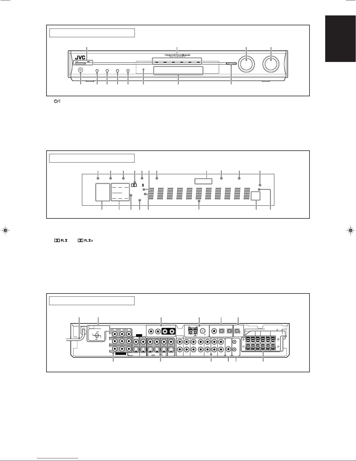
Parts identification ................................................ 2
Getting started ...................................................... 4
Before Installation .................................................................. 4
Checking the supplied accessories ....................................... 4
Putting batteries in the remote control ................................... 4
Setting the voltage selector ................................................... 4
Connecting the FM and AM antennas ................................... 5
Connecting the speakers ....................................................... 6
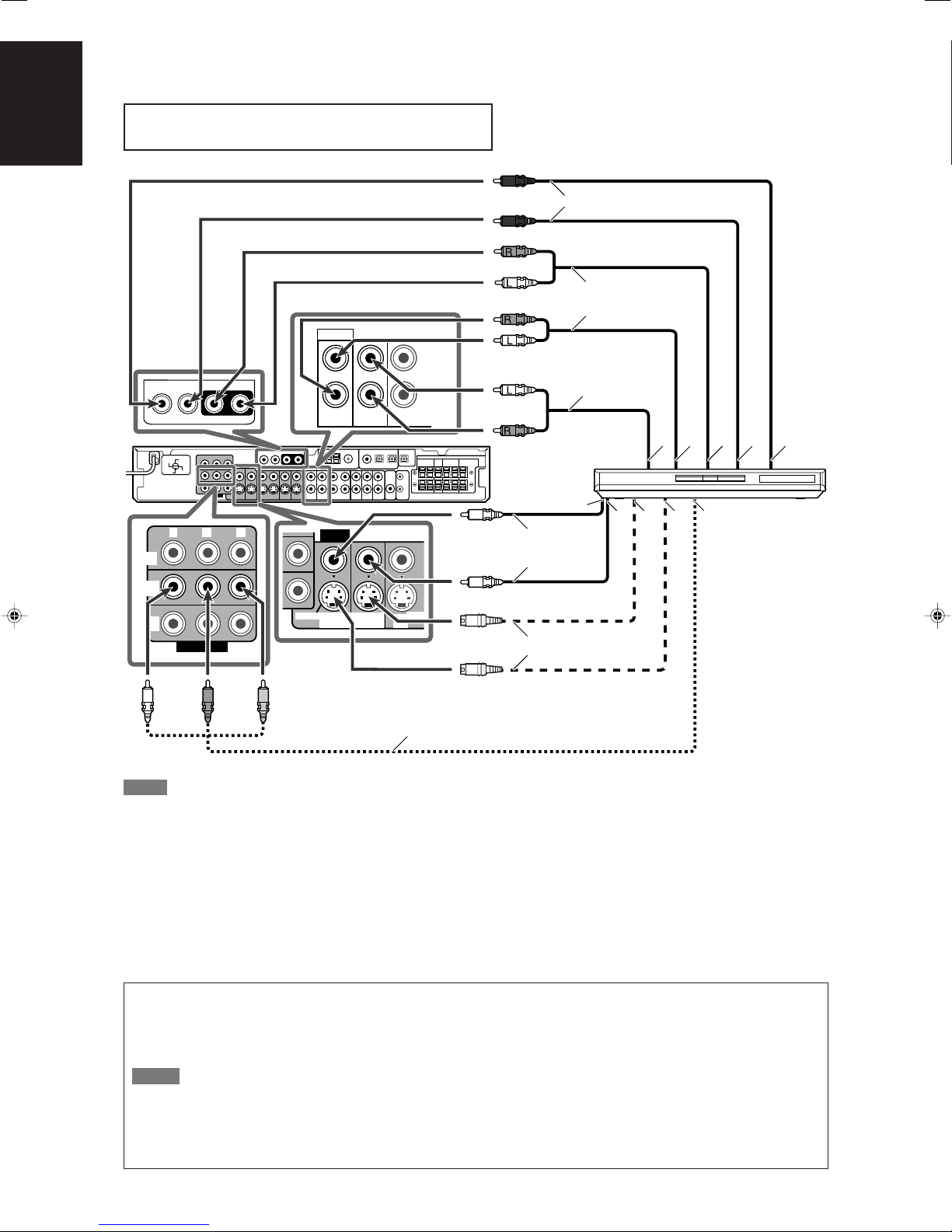
Connecting video components .............................................. 7
Connecting the power cord .................................................. 11
Basic operations ................................................. 12
1 Turn on the power ............................................................. 12
2 Select the source to play .................................................. 12
3 Adjust the volume ............................................................. 13
Selecting the digital decode mode ....................................... 13
Adjusting the subwoofer audio position ............................... 14
Activating TV Direct ............................................................. 14
Tu r ning off the sounds temporarily ...................................... 15
Changing the display brightness .......................................... 15
Tu r ning off the power with the Sleep Timer ......................... 15
Basic settings ...................................................... 16
Setting the speaker information automatically
—Smart Surround Setup ............................................... 16
Basic setting items ............................................................... 18
Operation through on-screen display menus ....................... 18
Menu operation buttons ................................................... 18
Setup menu configuration ............................................... 19
Menu operating procedure................................................... 20
Setting the items .................................................................. 21
Setting the speakers ....................................................... 21
Activating the EX/ES/PLIIx setting—EX/ES/PLIIx ........... 22
Selecting the main or sub channel—DUAL MONO ......... 23
Setting bass sound .......................................................... 23
Using the Midnight mode—MIDNIGHT MODE ............... 24
Setting the digital input (DIGITAL IN) terminals
—DIGITAL IN 1/2/3 ................................................... 24
Selecting the component video input mode
—DVD VIDEO INPUT/VCR VIDEO INPUT ............... 25
Superimposing the menus—SUPERIMPOSE ................ 25
Converting S-video signals into composite video signals
—DOWN MIX ............................................................ 25
Converting composite video signals into S-video signals
—Y/C SEPARATE ..................................................... 25
Sound adjustments ............................................. 26
Basic adjustment items ........................................................ 26
Operation through on-screen display menus ....................... 26
Menu operation buttons ................................................... 26
Setup menu configuration ............................................... 27
Menu operating procedure................................................... 28
Adjusting the items .............................................................. 29
Adjusting speaker output level ........................................ 29
Adjusting the equalization patterns
—DIGITAL EQ 63Hz/250Hz/1kHz/4kHz/16kHz ........ 30
Adjusting the bass sounds .............................................. 30
Adjusting the sound parameters for the
Surround/DSP modes ............................................... 31
Tuner operations ................................................. 32
Setting the AM tuner interval spacing .................................. 32
Tuning in to stations manually .............................................. 32
Using preset tuning .............................................................. 32
Selecting the FM reception mode ........................................ 33
Creating realistic sound fields ........................... 34
Reproducing theater ambience ........................................... 34
Introducing the Surround modes ......................................... 34
Introducing the DSP modes ................................................. 37
Using the Surround/DSP modes ......................................... 38
Activating the Surround/DSP modes ................................... 39
AV COMPU LINK remote control system .......... 40
Operating other JVC products ........................... 42
Operating other manufacturers’ products ........ 44
Troubleshooting .................................................. 47
Specifications ...................................................... 48
EN01-05RXF31S[US]2.p65 05.4.23, 16:151

2
English
SET
HOME CINEMA CONTROL CENTER
REMOTE CONTROL
RM-SRXF31U
4
2
t
3
1
5
9
8
7
q
w
e
r
u
y
i
o
p
6
Remote control
See pages in parentheses for details.
1TV DIRECT button (14)
2Source selecting buttons (12, 14, 32, 33)
DVR/DVD, VCR, DBS, TV, DVD MULTI, FM/AM
3Operating buttons for tuner (32, 33)
(TUNING, FM MODE, TUNING 9, MEMORY
4On-screen display operation buttons (18, 26)
Cursor buttons (3, 2, 5, ∞),
SET
5SMART SURROUND SETUP button (16)
6EX/ES button (22)
7SOUND button (13, 14, 22, 24, 30, 31)
8SURROUND button (39)
9Adjusting buttons for speaker and subwoofer output levels (29)
FRONT L +/–, FRONT R +/–, CENTER +/–, SUBWFR +/–,
SURR L +/–, SURR R +/–, S.BACK +/–
pAUDIO button (12, 14)
qMUTING button (15)
wVOLUME +/– button (13)
eMode selector (12, 14, 16, 18, 22, 24, 26, 29 – 32, 39)
DVR, DVD, AUDIO/TV/VCR/DBS
rMENU button (18, 26)
t•Numeric buttons (33)
• Adjusting buttons (13, 14, 24, 30, 31)
DECODE, EQ FREQ, BASS BOOST, C.TONE,
EQ LEVEL 9, MIDNIGHT, EFFECT, EQ LEVEL (,
A.POSITION
yDIMMER button (15)
uANALOG/DIGITAL INPUT button (12)
iTEST TONE button (17, 29)
oSLEEP button (15)
The buttons which are not indicated here can be used for
operating other JVC products or other manufacturers’ products.
For details, see pages 42 to 46.
•When operating this receiver, set the mode selector (e)
to “AUDIO/TV/VCR/DBS.”
•When operating a JVC DVD recorder, set the mode
selector (e) to “DVR.”
• When operating a JVC DVD player, set the mode selector
(e) to “DVD.”
Parts identification
To open the cover of the
remote control, push here
then slide downward.
EN01-05RXF31S[US]2.p65 05.4.23, 16:152

3
English
Front panel
1STANDBY/ON button and standby lamp (12, 14, 32)
2Source lamps
DVD MULTI, DVR/DVD, VCR, DBS, TV, FM/AM
3•SOURCE SELECTOR (12, 14, 33)
•MULTI JOG (18, 26, 33, 39)
4MASTER VOLUME control (13)
5PHONES jack (13)
6TV DIRECT button (14)
7SETTING button (18, 32)
8ADJUST button (26, 32)
9SURROUND button (39)
pRemote sensor (4)
qDisplay window (see below)
w•SET button (17, 18, 26)
•TUNER PRESET button (33)
Display window
1EQ indicator (30)
2C.TONE indicator (31)
3VIRTUAL SB indicator (38)
4and indicator (35)
5AUDIO P. (position) indicator (14)
6Neo:6 indicator (36)
7BASS indicator (30)
8Tuner operation indicators (32)
TUNED, ST (stereo)
9AUTO MUTING indicator (33)
0SLEEP indicator (15)
Rear panel
See pages in parentheses for details.
-ATT (attenuator) indicator (30)
=Digital signal format indicators (13, 34 – 36)
LPCM (Linear PCM), DOLBY D (Dolby Digital), DTS, 96/24
~Signal and speaker indicators (15)
!DSP indicator (36, 37)
@AUTO SR (surround) indicator (39)
#3D indicator (36, 37)
$Main display
%Frequency unit indicators
MHz (for FM station), kHz (for AM station)
^HP (headphones) indicator (13, 36, 37)
STANDBY / ON
TV DIRECT ADJUSTSETTING SURROUND
RX-F31 HOME CINEMA CONTROL CENTER
DVR MULTI DVR / DVD VCR DBS FM / AMTV
SET / TUNER PRESET
SOURCE
SELECTOR
/ MULTI JOG
MASTER
VOLUME
PHONES
7 8 96 w
3 4
p
2
q
1
5
EQ
LPCM L
LS SB RS
S . WFR
PL x
NEO : 6
DSP 3D
LFE
CR
DOLBY D
DTS AAC
96 / 24
AUTO SR
C.TONE VIRTUAL SB AUDIO P. BASS TA NEWS INFO RDS TUNED ST SLEEP
AUTO MUTING AUTO MODE
ATT
HP
MHz
kHz
1 2 578-
^%
@#
~!
=$
40
9
36
VIDEO
DBS
IN
VCR
VIDEO
OUT
(REC)
IN
(PLAY)
S-VIDEO
DVR
OUT (REC)
DVR/DVD
IN (PLAY)
MONITOR
OUT
CAUTION:SPEAKER
IMPEDANCE 6 – 16
ANTENNA
AM LOOP
AM EXT COAXIAL
FM 75
CENTER SURROUND SURROUND
BACK SPEAKERS
LEFTRIGHT LEFTRIGHT
FRONT
Y PBPR
COMPONENT
MONITOR
OUT
DVR/DVD
IN
VCR
IN
PCM/
STREAM
SURR-LSURR-RCENTERSUBWOOFER
DIGITAL OUT
DVD MULTI IN
3(VCR)2(DBS)
1(DVR/DVD)
DIGITAL IN
LINK-
III
L
R
TV
VCR DBS
ININ(PLAY)(REC)
DVR
OUT (REC)
DVR/DVD
IN
MONITOR
OUT
AUDIO
OUT
SUB-
WOOFER
(PLAY)
OUT IN
AV
COMPU
110V
127V
220V
230 -
240V
VOLTAGE
SELECTOR
1
9
3 64
w
8
7
5
p q
2
1Power cord (11)
2VOLTAGE SELECTOR (4)
3DVD MULTI IN jacks (8)
SUBWOOFER, CENTER, SURR-R, SURR-L
4ANTENNA terminals (5)
5DIGITAL IN terminals (11)
•Coaxial: 1(DVR/DVD)
•Optical: 2(DBS), 3(VCR)
6DIGITAL OUT terminal (11)
7COMPONENT (Y, PB, PR) jacks (7 – 10)
VCR IN, DVR/DVD IN, MONITOR OUT
8VIDEO terminals (7 – 10)
VIDEO (composite video) jacks, S-VIDEO terminals
•Input: DVR/DVD IN (PLAY), VCR IN (PLAY), DBS IN
•Output: DVR OUT (REC), VCR OUT (REC), MONITOR OUT
9AUDIO jacks (7 – 10)
• Input: DVR/DVD IN (PLAY), VCR IN (PLAY), DBS IN, TV IN
•Output: DVR OUT (REC), VCR OUT (REC), MONITOR OUT
pSUBWOOFER OUT jack (6)
qAV COMPU LINK-III terminals (40)
wSPEAKERS terminals (6)
FRONT, CENTER, SURROUND, SURROUND BACK
EN01-05RXF31S[US]ff.p65 05.6.9, 17:033

4
English
Putting batteries in the remote control
Before using the remote control, put two supplied batteries first.
1
Press and slide the battery cover on the back
of the remote control.
2
Insert batteries.
Make sure to match the polarity: (+) to (+) and (–) to (–).
3
Replace the cover.
If the range or effectiveness of the remote control decreases,
replace the batteries. Use two R6(SUM-3)/AA(15F) type dry-cell
batteries.
•Supplied butteries are for initial setup. Replace for continued
use.
CAUTION:
Follow these precautions to avoid leaking or cracking cells:
•Place batteries in the remote control so they match the polarity:
(+) to (+) and (–) to (–).
•Use the correct type of batteries. Batteries that look similar may
differ in voltage.
•Always replace both batteries at the same time.
•Do not expose batteries to heat or flame.
When using the remote control, aim the remote control directly at
the remote sensor on the front panel.
Remote sensor
Setting the voltage selector
Before connections, always do the following first if necessary.
Select the correct voltage in VOLTAGE SELECTOR on the rear
of the receiver by using a screw driver.
•Check to be sure if the voltage mark is set to the voltage for
your area where this unit plugs in.
Getting started
Before Installation
General precautions
•Be sure your hands are dry.
•Turn the power off to all components.
•Read the manuals supplied with the components you are going
to connect.
Locations
•Install the receiver in a location that is level and protected from
moisture and dust.
•The temperature around the receiver must be between –5˚C
and 35˚C.
•Make sure there is good ventilation around the receiver. Poor
ventilation could cause overheating and damage the receiver.
•Leave sufficient distance between the receiver and the TV.
Handling the receiver
•Do not insert any metal object into the receiver.
•Do not disassemble the receiver or remove screws, covers, or
cabinet.
•Do not expose the receiver to rain or moisture.
•Do not pull on the power cord to unplug the cord. When
unplugging the cord, always grasp the plug so as not to damage
the cord.
•When you are away on travel or otherwise for an extended
period or time, remove the plug from the wall outlet. A small
amount of power is always consumed while the power cord is
connected to the wall outlet.
The receiver has a built-in cooling fan which operates
while the receiver is turned on. Be sure to leave enough
ventilation to obtain sufficient cooling effect.
CAUTION:
Do not connect the AC power plug to the wall outlet until all
connections are completed.
Checking the supplied accessories
Check to be sure you have all of the following supplied
accessories. If anything is missing, contact your dealer
immediately.
•Remote control (×1)
•Batteries (×2)
•AM loop antenna (×1)
•FM antenna (×1)
•Digital coaxial cable (×1)
•AC plug adaptor (×1)
To operate the receiver, set
the mode selector to
“AUDIO/TV/VCR/DBS.”
123
110V
127V
220V
230 -
240V
VOLTAGE
SELECTOR
Voltage mark
EN01-05RXF31S[US]3.p65 05.5.11, 18:054

5
English
110V
127V
220V
230 -
240V
ANTENNA
AM LOOP
AM EXT COAXIAL
FM 75
ANTENNA
Snap the tabs on the loop
into the slots of the base to
assemble the AM loop
antenna.
Connecting the FM and AM antennas
Do not connect the AC power plug to the wall outlet until all connections are completed.
AM loop antenna
(supplied)
If AM reception is poor, connect
an outdoor single vinyl-covered
wire (not supplied).
AM antenna connection
Connect the AM loop antenna supplied to the AM LOOP
terminals.
Connect the white cord to the AM EXT terminal, and connect the
black cord to the Hterminal.
Turn the loop until you have the best reception.
•If the reception is poor, connect an outdoor single vinyl-covered
wire (not supplied) to the AM EXT terminal. Keep the AM loop
antenna connected.
FM antenna connection
Connect the FM antenna supplied to the FM 75 ΩCOAXIAL
terminal as a temporary measure.
Extend the supplied FM antenna horizontally.
• If the reception is poor, connect an outdoor FM antenna (not
supplied). Before attaching a 75 Ωcoaxial cable with a
connector (IEC or DIN 45325) , disconnect the supplied FM
antenna.
FM antenna (supplied)
NOTES
•If the AM loop antenna wire is covered with vinyl,
remove the vinyl while twisting it as shown on the
right.
•Make sure the antenna conductors do not touch
any other terminals, connecting cords and power
cord. This could cause poor reception.
If FM reception is poor, connect an
outdoor FM antenna (not supplied).
EN01-05RXF31S[US]2.p65 05.4.23, 16:155

6
English
LR
LS RS
SB
C
SW
110V
127V
220V
230 -
240V
CAUTION:SPEAKER
IMPEDANCE 6 – 16
CENTER SURROUND SURROUND
BACK SPEAKERS
LEFTRIGHT LEFTRIGHT
FRONT
LINK-
III
OUT
SUB-
WOOFER
AV
COMPU
Connecting the speakers
Turn off all components before making connections.
1
Twist and remove the insulation at the end of each
speaker cord.
2
Press and hold the clamp of the speaker terminal
(1), then insert the speaker cord (2).
•For each speaker, connect the (+) and (–) terminals on the
rear panel to the (+) and (–) terminals marked on the
speakers.
3
Release the finger from the clamp.
CAUTIONS:
•Use speakers with the SPEAKER IMPEDANCE indicated by the
speaker terminals (6 Ω– 16 Ω).
•DO NOT connect more than one speaker to one speaker
terminal.
Connecting the speakers
Do not connect the AC power plug to the wall outlet until all connections are completed.
Speaker Layout Diagram
Powered
subwoofer
(SW)
Connecting the powered subwoofer
By connecting a subwoofer, you can enhance the bass or
reproduce the original LFE signals recorded in digital software.
Connect the input jack of a powered subwoofer to the
SUBWOOFER OUT jack on the rear panel, using a cord
with RCA pin plugs (not supplied).
• Refer also to the manual supplied with your subwoofer.
After connecting all the speakers and/or a subwoofer, set the
speaker setting information properly to obtain the best possible
surround effect. For details, see pages 16, 17, and 21 to 23.
NOTE
You can place a subwoofer wherever you like since bass sound is
non-directional. Normally place it in front of you.
Left front speaker
(L)
Right surround
speaker (RS)
Left surround
speaker (LS)
Center speaker (C)
1
2
123
Surround back
speaker (SB)
Right front speaker
(R)
EN06-11RXF31S[US]4.p65 05.5.12, 17:156

7
English
This receiver is equipped with the following video terminals—
composite video, S-video, and component video terminals.
• If your video components have S-video (Y/C-separation) and/or
component video (Y, PB, PR) jacks, connect them using an S-
video cable (not supplied) or component video cable (not
supplied). By using these terminals, you can get a better picture
quality in the order:
Component > S-video > Composite
IMPORTANT:
Component video signals are transmitted only through component
video output jacks. Therefore, if a recording video component and
a playing video component are connected to the receiver through
the video terminals of different type, you cannot record the picture.
In addition, if the TV and a playing video component are
connected to the receiver through the video terminals of different
type, you cannot view the playback picture on the TV.
On the other hand, S-video signals and composite video signals
can be converted into each other and transmitted through the
corresponding output jack. For details about the settings of the
conversion, see page 25.
110V
127V
220V
230 -
240V
VIDEO
VCR
OUT
(REC)
VCR
OUT
(REC)
DVR
OUT (REC)
DVR/DVD
IN (PLAY)
AUDIO
Y P
B
P
R
MONITOR
OUT
DVR/DVD
IN
VCR
IN
COMPONENT
DVR/DVD
IN (PLAY)
DVR
OUT (REC)
S-VIDEO
Åı
Î‰Ï Ì
Ç
Turn off all components before making connections.
•When you connect other components, refer also to their
manuals.
DO NOT use a TV through a VCR or a TV with a built-in
VCR; otherwise, the picture may be distorted.
CAUTION:
If you connect a sound-enhancing device such as a graphic
equalizer between the source components and this receiver, the
sound output through this receiver may be distorted.
If your video components have AV COMPU LINK terminal
See also page 40 for detailed information about the connection
and the AV COMPU LINK remote control system.
ÅTo left/right audio channel output
ıOnly for DVD recorder: To left/right audio channel
input
ÇOnly for DVD recorder: To composite video input
ÎTo composite video output
‰To S-video output
ÏOnly for DVD recorder: To S-video input
ÌTo component video output
•Connect Y, PB, and PRcorrectly.
White
Red
DVD recorder or
DVD player
White
Stereo audio cable
(not supplied)
Green Blue Red
Component video cable (not supplied)
S-video cable (not supplied)
Composite video cable
(not supplied)
7Connecting a DVD recorder or DVD player with its stereo output jacks (DVR/DVD):
Connecting video components
Do not connect the AC power plug to the wall outlet until all connections are completed.
NOTES
•When connecting a DVD recorder or DVD player to the
component video input jacks, make the component video input
setting (DVD VIDEO INPUT) correctly. If you do not, you cannot
view the playback picture on the TV or the AV COMPU LINK
remote control system cannot operate properly. For details, see
page 25.
•You can enjoy digital sound if using a digital coaxial or optical
cable. When shipped from the factory, the audio input mode for
a DVD recorder and DVD player is set to use the digital coaxial
terminal (DIGITAL IN 1 (DVR/DVD)). For details of digital
connection, see page 11.
Red
EN06-11RXF31S[US]FF.p65 05.6.9, 17:037

8
English
110V
127V
220V
230 -
240V
VIDEO
VCR
OUT
(REC)
Y P
B
P
R
MONITOR
OUT
DVR/DVD
IN
VCR
IN
COMPONENT
DVR/DVD
IN (PLAY)
DVR
OUT (REC)
S-VIDEO
VCR
OUT
(REC)
DVR
OUT (REC)
DVR/DVD
IN (PLAY)
AUDIO
SURR-LSURR-RCENTERSUBWOOFER
DVD MULTI IN
Åı Ç Î ‰
Ì Ó È Ô
Ï
7Connecting a DVD recorder or DVD player with its analog discrete output jacks (DVD MULTI IN):
This connection is the best connection method for enjoying DVD Audio sounds. When a DVD Audio disc is played back, the original high-
quality sounds can be reproduced only using this connection.
Turn off all components before making connections.
•When you connect other components, refer also to their manuals.
Stereo audio cable
(not supplied)
About “DVD MULTI”
When you select “DVD MULTI” as the source (see page 12), you can enjoy analog discrete output sound (5.1-channel reproduction)
from the connected component.
•You may need to select analog discrete output mode on the component.
NOTES
•When using the headphones, you can listen to the front channel sounds (left and right) only. 3D HEADPHONE mode (see pages 36
and 37) is not available.
•When TV Direct is activated while “DVD MULTI” is selected as the source, the source changes to the last selected source—
“DVR/DVD,” “VCR,” and “DBS” (see page 14).
•Surround/DSP modes (see pages 34 to 39) are not available for “DVD MULTI.”
White
Red
White
Red
Monaural audio cable
(not supplied)
Component video cable (not supplied)
Composite video
cable (not supplied)
S-video cable (not supplied)
ÅTo left/right front channel audio output
ıOnly for DVD recorder: To left/right front channel
audio input
ÇTo left/right surround channel audio output
ÎTo center channel audio output
‰To subwoofer output
ÏOnly for DVD recorder: To composite video input
ÌTo composite video output
ÓTo S-video output
ÈOnly for DVD recorder: To S-video input
ÔTo component video output
•Connect Y, PB, and PRcorrectly.
Green Blue Red
Stereo audio cable
(not supplied)
NOTE
When connecting a DVD recorder or DVD player to the
component video input jacks, make the component video input
setting (DVD VIDEO INPUT) correctly. If you do not, you cannot
view the playback picture on the TV or the AV COMPU LINK
remote control system cannot operate properly. For details, see
page 25.
White
Red
DVD recorder or
DVD player
EN06-11RXF31S[US]FF.p65 05.6.9, 17:038

9
English
110V
127V
220V
230 -
240V
TV
VCR DBS
IN
IN
IN
(PLAY)
DBS
IN
VCR MONITOR
OUT
IN
(PLAY)
Å
ıÇ
110V
127V
220V
230 -
240V
VCR DBS
IN
IN
(PLAY)
OUT
(REC)
DVR/DVD
IN (PLAY)
Y PBPR
MONITOR
OUT
DVR/DVD
IN
VCR
IN
COMPONENT
DBS
IN
VCR
OUT
(REC)
IN
(PLAY)
DVR/DVD
IN (PLAY)
‰ÏÌ
Î
Ç
Å ı
7Connecting a VCR
ÅTo left/right audio channel output
ıTo left/right audio channel input
ÇTo composite video input
ÎTo composite video output
‰To S-video output
ÏTo S-video input
ÌTo component video output
•Connect Y, PB, and PRcorrectly.
Stereo audio cable (not supplied)
White
Red
White
Component video cable (not supplied)
Composite video
cable (not supplied)
S-video cable (not supplied)
Red
Green Blue Red
VCR
NOTES
•When connecting a VCR to the component video input jacks,
make the component video input setting (VCR VIDEO INPUT)
correctly. If you do not, you cannot view the playback picture on
the TV or the AV COMPU LINK remote control system cannot
operate properly. For details, see page 25.
•You can enjoy digital sound if using a digital coaxial or optical
cable. When shipped from the factory, the audio input mode for
a video component other than DVD recorder and DVD player is
set to use the digital optical terminal (DIGITAL IN 3 (VCR)). For
details of digital connection, see page 11.
Turn off all components before making connections.
•When you connect other components, refer also to their manuals.
Stereo audio cable (not supplied)
Composite video cable (not supplied)
DBS tuner
NOTE
You can enjoy digital sound if using a digital coaxial or optical
cable. When shipped from the factory, the audio input mode for a
TV is set to use the digital optical terminal (DIGITAL IN 2 (DBS)).
For details of digital connection, see page 11.
White
Red
S-video cable (not supplied)
7Connecting a DBS tuner
ÅTo left/right audio channel output
ıTo composite video output
ÇTo S-video output
EN06-11RXF31S[US]FF.p65 05.6.9, 18:329

10
English
110V
127V
220V
230 -
240V
L
R
TVDBS ININ MONITOR
OUT OUT
SUB-
WOOFER
DBS
IN
MONITOR
OUT
Y PBPR
MONITOR
OUT
DVR/DVD
IN
VCR
IN
COMPONENT
Å ı
Ç Î ‰
7Connecting a TV
Connect the TV to the appropriate MONITOR OUT jacks to view the playback picture from any other connected video components.
Stereo audio cable
(not supplied)
Red
Component video cable (not supplied)
TV
Composite video cable
(not supplied)
Green Blue
White
Red
S-video cable (not supplied)
White
Red
ÅTo left/right audio channel input
ıTo left/right audio channel output
ÇTo composite video input
ÎTo S-video input
‰To component video input
•Connect Y, PB, and PRcorrectly.
NOTES
•You can enjoy digital sound if using a digital coaxial or optical
cable. For details of digital connection, see page 11.
•When connecting a TV through the COMPONENT MONITOR
OUT jacks, the on-screen display does not appear on the TV
screen (see page 25).
IMPORTANT:
Audio signals come out through the MONITOR OUT (L/R) jacks
ONLY when TV Direct is in use (see page 14).
Connect these jacks to the audio input jacks corresponding to the
video connection; otherwise, no sound comes out of the TV
speaker when TV Direct is in use.
Turn off all components before making connections.
•When you connect other components, refer also to their manuals.
EN06-11RXF31S[US]FF.p65 05.6.9, 18:3210

11
English
110V
127V
220V
230 -
240V
PCM/
STREAM
DIGITAL OUT
110V
127V
220V
230 -
240V
DIGITAL IN
3(VCR)2(DBS)1(DVR/DVD)
NOTES
•When shipped from the factory, the DIGITAL IN terminals have
been set for use with the following components:
–1(DVR/DVD): For DVD recorder or DVD player
–2(DBS): For DBS tuner
–3(VCR): For VCR
If you connect other components, change the digital input
(DIGITAL IN) terminal setting correctly. See “Setting the digital
input (DIGITAL IN) terminals—DIGITAL IN 1/2/3” on page 24.
• Select the digital input mode. See “Selecting the analog or
digital input mode” on page 12.
•When you want to operate the connected component (except
DBS tuner) using the AV COMPU LINK remote control system
(see pages 40 and 41), connect them also as described on
pages 7 to 10.
Digital connection
This receiver is equipped with three DIGITAL IN terminals—one
digital coaxial terminal and two digital optical terminals—and one
DIGITAL OUT terminal.
To reproduce the digital sound, use the digital connection in
addition to the analog connection methods described on pages 7
to 10.
Digital coaxial cable (supplied: 1 cable)
Digital optical cable (not supplied)
Turn off all components before making connections.
•When you connect other components, refer also to their
manuals.
7Digital input terminals
When the component has a digital coaxial output
terminal, connect it to the 1(DVR/DVD) terminal,
using a digital coaxial cable (supplied).
When the component has a digital optical output
terminal, connect it to the 2(DBS) or 3(VCR)
terminal, using a digital optical cable (not supplied).
Before connecting a digital
optical cable, unplug the
protective plug.
NOTE
The digital signal format transmitted through the DIGITAL OUT
terminal is the same as that of the input signal. For example,
when the DTS signals are input, the DTS signals are transmitted.
Connecting the power cord
When all the audio/video connections have been made, connect
the AC power plug to the wall outlet. Make sure that the plugs are
inserted firmly. The standby lamp lights in red.
CAUTIONS:
•Do not plug in before setting the VOLTAGE SELECTOR switch
on the rear of the receiver and all connection procedures are
complete.
•Do not touch the power cord with wet hands.
• Do not alter, twist or pull the power cord, or put anything heavy
on it, which may cause fire, electric shock, or other accidents.
• If the cord is damaged, consult a dealer and have the power
cord replaced with a new one.
NOTES
•Keep the power cord away from the connecting cables and the
antenna. The power cord may cause noise or screen
interference.
•The preset settings such as preset channels and sound
adjustment may be erased in a few days in the following cases:
–When you unplug the power cord.
–When a power failure occurs.
•If the wall outlet does not match the AC plug, use the supplied
AC plug adaptor.
7Digital output terminal
You can connect any digital components which have an optical
digital input terminal.
Connecting digital recording equipment to the
DIGITAL OUT terminal enables you to perform
digital-to-digital recording.
EN06-11RXF31S[US]3.p65 05.5.11, 18:0611

12
English
Basic operations
2
Select the source to play
On the front panel:
Turn SOURCE SELECTOR until the source name
you want appears on the display.
The source lamp corresponding to the selected source lights in
red.
•As you turn SOURCE SELECTOR, the source changes as
follows:
DVD MULTI: Select for the DVD player using the analog
discrete output mode (5.1-channel
reproduction).
DVR/DVD (DGT)*: Select for the DVD recorder or DVD player.
VCR (DIGITAL)*:Select for the VCR.
DBS (DIGITAL)*:Select for the DBS tuner.
TV (DIGITAL)*:Select for the TV.
FM: Select for an FM broadcast.
AM: Select for an AM broadcast.
From the remote control:
Press one of the source selecting buttons.
•For the tuner, press FM/AM. Each time you press FM/AM, the
band alternates between “FM” and “AM.”
*Selecting the analog or digital input mode
For a component you have connected using both the analog
connection and the digital connection methods (see pages 7 to 11),
you need to select the correct input mode.
•You can select the digital input only for sources which you have
selected digital input terminals for. (See “Setting the digital input
(DIGITAL IN) terminals—DIGITAL IN 1/2/3” on page 24.)
From the remote control ONLY:
Press ANALOG/DIGITAL INPUT to select the
analog or digital input mode.
•Each time you press the button, the input mode alternates
between the analog input (“ANALOG”) and the digital input
(“DGTL AUTO”).
This setting is memorized for each source.
DGTL AUTO: Select for the digital input mode. The receiver
automatically detects the incoming signal
format, then the digital signal format indicator
(LPCM, DOLBY D, DTS, or DTS 96/24) for
the detected signal lights up.
ANALOG: Select for the analog input mode.
Initial setting: DGTL AUTO
NOTE
When you select “DVD MULTI,” “FM,” or “AM” as the source, the
analog and digital input mode is not available.
1
Turn on the power
Press STANDBY/ON (or AUDIO on the
remote control).
The standby lamp goes off and the source lamp of the current
source lights in red.
Current source name appears.
To turn off the power (into standby)
Press STANDBY/ON (or AUDIO on the remote control)
again.
The standby lamp lights in red.
NOTE
A small amount of power is consumed in standby mode. To turn
the power off completely, unplug the AC power cord.
When operating the receiver
using the remote control, set
the mode selector to
“AUDIO/TV/VCR/DBS.”
Source lamps
The on-screen display appears on the TV screen for 5 seconds
(except “turning off the sounds temporarily”) to show the
indication in the following cases:
–When you select the source (see right column).
– When you adjust the volume (see page 13).
–When you turn off the sounds temporarily (see page 15).
–When you select the Surround/DSP modes (see page 39).
To cancel the function, set “SUPERIMPOSE” to “SUPERIMPOSE:
OFF” (see page 25).
12 3
EQ
LPCM L
LS SB RS
S . WFR
PL
NEO : 6
DSP 3D
LFE
CR
DOLBY D
DTS AAC
96 / 24
AUTO SR
C.TONE VIRTUAL SB AUDIO P. BASS TA NEWS INFO RDS TUNED ST SLEEP
AUTO MUTING AUTO MODE
ATT
HP
MHz
kHz
EQ
LPCM L
LS SB RS
S . WFR
PL
NEO : 6
DSP 3D
LFE
CR
DOLBY D
DTS AAC
96 / 24
AUTO SR
C.TONE VIRTUAL SB AUDIO P. BASS TA NEWS INFO RDS TUNED ST SLEEP
AUTO MUTING AUTO MODE
ATT
HP
MHz
kHz
DVR/DVD (DGT)
DVD MULTI
VCR (DIGITAL) DBS (DIGITAL)
TV (DIGITAL) FM AM
(Back to the beginning)
1
3
2
EN12-15RXF31S[US]3.p65 05.5.11, 18:2112

13
English
3
Adjust the volume
To increase the volume, turn MASTER VOLUME
control clockwise (or press VOLUME + on the
remote control).
To decrease the volume, turn MASTER VOLUME
control counterclockwise (or press VOLUME – on
the remote control).
•When you adjust the volume, the volume level indication
appears on the display for a while.
CAUTION:
Always set the volume to the minimum before starting any
sources. If the volume is set at its high level, the sudden blast of
sound energy can permanently damage your hearing and/or ruin
your speakers.
NOTE
The volume level can be adjusted within the range of “0”
(minimum) to “50” (maximum).
Listening with headphones
You can enjoy not only stereo software but also multi-channel
software through the headphones. (Sounds are down-mixed to the
front channels while playing multi-channel software.)
Connect a pair of headphones to the PHONES jack on the
front panel to activate the HEADPHONE mode.
The HP (headphone) indicator lights up on the display.
•You can also enjoy the Surround/DSP mode through the
headphones—3D HEADPHONE mode. For details, see pages
36 and 37.
•Disconnecting a pair of headphones from the PHONES jack
cancels the HEADPHONE (or 3D HEADPHONE) mode and
activates the speakers.
CAUTION:
Be sure to turn down the volume:
•Before connecting or putting on headphones, as high volume
can damage both the headphones and your hearing.
• Before removing headphones, as high volume may output from
the speakers.
Selecting the digital decode mode
If the following symptoms occur while playing Dolby Digital or DTS
software with “DGTL AUTO” selected (see page 12), follow the
procedure below:
•Sound does not come out at the beginning of playback.
•Noise comes out while searching for or skipping chapters or
tracks.
From the remote control ONLY:
Press SOUND, then press DECODE to select
“DOLBY D” or “DTS.”
•Each time you press DECODE, the digital decode mode
changes as follows:
•To play back software encoded with Dolby Digital, select
“DOLBY D.”
•To play back software encoded with DTS, select “DTS.”
NOTES
•When you turn off the power or select another source,
“DOLBY D” or “DTS” is canceled and the digital decode mode is
automatically reset to “DGTL AUTO.”
•After pressing SOUND, the numeric buttons work for sound
adjustments. To use the numeric buttons to operate your target
source, press the corresponding source selecting button before
operation; otherwise, the remote control may not work as you
intend.
The following digital signal format indicators on the display
indicate what type of signal comes into the receiver.
LPCM: Lights up when Linear PCM signal comes in.
DOLBY D: •Lights up when Dolby Digital signal comes in.
•Flashes when “DOLBY D” is selected for any
software other than Dolby Digital.
DTS: •Lights up when conventional DTS signal comes
in.
•Flashes when “DTS” is selected for any
software other than DTS.
DTS 96/24: Lights up when DTS 96/24 signal comes in.
NOTE
When “DGTL AUTO” cannot recognize the incoming signal, no
digital signal format indicator lights up on the display.
EQ
LPCM L
LS SB RS
S . WFR
PL
NEO : 6
DSP 3D
LFE
CR
DOLBY D
DTS AAC
96 / 24
AUTO SR
C.TONE VIRTUAL SB AUDIO P. BASS TA NEWS INFO RDS TUNED ST SLEEP
AUTO MUTING AUTO MODE
ATT
HP
MHz
kHz
DOLBY D
DTS
(Back to the beginning)
DGTL AUTO
EQ
LPCM L
LS SB RS
S . WFR
PL
NEO : 6
DSP 3D
LFE
CR
DOLBY D
DTS AAC
96 / 24
AUTO SR
C.TONE VIRTUAL SB AUDIO P. BASS TA NEWS INFO RDS TUNED ST SLEEP
AUTO MUTING AUTO MODE
ATT
HP
MHz
kHz
EN12-15RXF31S[US]2.p65 05.4.23, 16:1613

14
English
Adjusting the subwoofer audio
position
If the subwoofer sound is much reinforced for stereo sound
compared to the sound reproduced with multi-channel, set the
subwoofer audio position. The subwoofer output level is
automatically decreased by the selected value when you are
listening in stereo.
The AUDIO P. indicator lights up when this function is activated.
•Once you have made an adjustment, it is memorized for each
source.
From the remote control ONLY:
Press SOUND, then press A.POSITION repeatedly.
•Each time you press A.POSITION, the subwoofer audio position
level changes as follows:
AUDIO P. indicator
The smaller the number becomes, the more the level decreases
automatically when listening in stereo.
•If no adjustment is required, select “OFF” (initial setting).
NOTES
•The minimum subwoofer output level is –10 dB.
Ex.: When setting the subwoofer output level to “–8 (dB)” and
the subwoofer audio position to “–4 (dB),” the subwoofer
output level when listening in stereo will be –10 dB.
To adjust the subwoofer output level, see page 29.
•This function is not available when the Surround/DSP mode is
activated or “DVD MULTI” is selected.
•After pressing SOUND, the numeric buttons work for sound
adjustments. To use the numeric buttons to operate your target
source, press the corresponding source selecting button before
operation; otherwise, the remote control may not work as you
intend.
Activating TV Direct
TV Direct enables you to use this receiver as an AV selector
while the receiver is turned off.
When TV Direct is activated, the pictures and sounds go from the
video components such as DVD player to the TV through this
receiver. Thus, you can use the video components and the TV as
if they were connected directly.
•This function takes effect for the following sources—DVR/DVD,
VCR, and DBS.
To activate (or deactivate) TV Direct, follow the procedure below:
1
Press TV DIRECT.
All the indications disappear, then the source lamp of the
current source lights in green.
2
Turn on the video component and TV.
3
Select the target video component.
On the front panel:
Turn SOURCE SELECTOR until one of the
source lamps—DVR/DVD, VCR, or DBS—lights
in green.
From the remote control:
Press one of the source selecting buttons—
DVR/DVD, VCR, or DBS.
The source lamp corresponding to the selected source lights
in green.
To cancel TV Direct and turn off the receiver, press
STANDBY/ON on the front panel (or AUDIO on the remote
control).
The receiver is turned off and the standby lamp lights up.
To cancel TV Direct and turn on the receiver, press TV DIRECT
again.
The receiver is turned on and the source lamp currently selected
lights in red.
NOTES
•When TV Direct is activated, you cannot enjoy any of the sound
effects the receiver produces, and cannot use the speakers
connected to the receiver.
•When TV Direct is activated while “DVD MULTI,” “FM,” or “AM” is
selected as the source, the source changes to the last selected
source—“DVR/DVD,” “VCR,” or “DBS.”
When operating the receiver
using the remote control, set
the mode selector to
“AUDIO/TV/VCR/DBS.”
EQ
LPCM L
LS SB RS
S . WFR
PL
NEO : 6
DSP 3D
LFE
CR
DOLBY D
DTS AAC
96 / 24
AUTO SR
C.TONE VIRTUAL SB AUDIO P. BASS TA NEWS INFO RDS TUNED ST SLEEP
AUTO MUTING AUTO MODE
ATT
HP
MHz
kHz
–2 –4 –6
OFF (canceled)
EN12-15RXF31S[US]2.p65 05.4.23, 16:1614

15
English
Turning off the sounds temporarily
From the remote control ONLY:
Press MUTING to turn off the sound through all
connected speakers and headphones.
“MUTING” appears on the display and the volume turns off.
To restore the sound, press MUTING again.
•Pressing VOLUME +/– (or turning MASTER VOLUME control
on the front panel) also restores the sound.
Changing the display brightness
You can dim the display—Dimmer.
From the remote control ONLY:
Press DIMMER repeatedly.
•Each time you press the button, the display brightness changes
as follows:
DIMMER 1: Dims the display slightly.
Dims the blue illumination slightly.
DIMMER 2: Dims the display more than DIMMER 1.
Dims the blue illumination slightly (more than
DIMMER 1).
DIMMER 3: Turns off the display and blue illumination.
(Temporarily canceled when you operate the
receiver.*)
DIMMER OFF: Cancels the Dimmer (normal display).
*Except when activating or deactivating TV Direct.
Turning off the power with the Sleep
Timer
You can fall asleep while listening to music—Sleep Timer.
From the remote control ONLY:
Press SLEEP repeatedly.
• Each time you press the button, the shut-off time changes in 10
minute intervals. The SLEEP indicator lights up on the display.
SLEEP indicator
When the shut-off time comes:
The receiver turns off automatically.
To check or change the remaining time until the shut-off
time:
Press SLEEP once.
The remaining time (in minutes) until the shut-off time appears.
•To change the shut-off time, press SLEEP repeatedly.
To cancel the Sleep Timer:
Press SLEEP repeatedly so that “SLEEP OFF” appears on the
display. (The SLEEP indicator goes off.)
•The Sleep Timer is also canceled when:
–You turn off the receiver, or
– TV Direct is activated.
Basic adjustment of auto memory
This receiver memorizes sound settings for each source:
•when you turn off the power, and
•when you change the source.
When you change the source, the memorized settings for the
newly selected source are automatically recalled.
The following can be stored for each source:
•Analog/digital input mode (see page 12)
•Subwoofer audio position (see page 14)
•Midnight mode (see page 24)
•Speaker output level (see page 29)
•Digital equalization pattern (see page 30)
•Bass boost (see page 30)
•Subwoofer phase (see page 30)
•Input attenuator mode (see page 30)
• Surround/DSP mode selection (see page 39)
NOTE
If the source is “FM” or “AM,” you can assign a different setting
for each band.
Signal and speaker indicators on the display
Signal indicators Speaker indicators
The signal indicators light up as follows:
L: • When digital input is selected: Lights up when the
left channel signal comes in.
•When analog input is selected: Always lights up.
R: • When digital input is selected: Lights up when the
right channel signal comes in.
•When analog input is selected: Always lights up.
C: Lights up when the center channel signal comes in.
LS*: Lights up when the left surround channel signal comes
in.
RS*: Lights up when the right surround channel signal comes
in.
SB: Lights up when the surround back channel signal
comes in.
LFE: Lights up when the LFE channel signal comes in.
*When monaural surround signal comes in, only “S” lights up.
NOTE
When “DVD MULTI” is selected as the source, all the signal
indicators except “SB” light up.
The speaker indicators light up as follows:
•The subwoofer indicator (
S . WFR
) lights up when
“SUBWOOFER” is set to “SUBWOOFER:YES.” For details,
see page 21.
•The other speaker indicators light up only when the
corresponding speaker is set to “SMALL” or “LARGE,” and
also when required for the current playback.
EQ
LPCM L
LS SB RS
S . WFR
PL
NEO : 6
DSP 3D
LFE
CR
DOLBY D
DTS AAC
96 / 24
AUTO SR
C.TONE VIRTUAL SB AUDIO P. BASS TA NEWS INFO RDS TUNED ST SLEEP
AUTO MUTING AUTO MODE
ATT
HP
MHz
kHz
10 20 30 40 50 60
90OFF (canceled) 80 70
EQ
LPCM L
LS SB RS
S . WFR
PL
NEO : 6
DSP 3D
LFE
CR
DOLBY D
DTS AAC
96 / 24
AUTO SR
C.TONE VIRTUAL SB AUDIO P. BASS TA NEWS INFO RDS TUNED ST SLEEP
AUTO MUTING AUTO MODE
ATT
HP
MHz
kHz
EQ
LPCM L
LS RS
S . WFR
PL x
NEO : 6
DSP 3D
LFE
CR
DOLBY D
DTS AAC
96 / 24
AUTO SR
C.TONE VIRTUAL SB AUDIO P. BASS TA NEWS INFO RDS
SB
L
LS SB RS
S . WFR LFE
CRL
LS SB RS
S . WFR LFE
CR
EN12-15RXF31S[US]2.p65 05.4.23, 16:1615

16
English
From the remote control ONLY:
1
Take your position where you listen to the
sound.
•Make sure speaker cables are connected firmly.
2
Press and hold SMART SURROUND SETUP
until “SETTING UP” flashes.
*1 L: Left front speaker
*2 C: Center speaker
*3 R: Right front speaker
*4 RS: Right surround speaker
*5 SB: Surround back speaker
*6 LS: Left surround speaker
3
When “CLAP YOUR HANDS.” appears, clap
your hands over your head once while the
indications still remain.
• On the display, “SETTING UP” stops flashing.
The receiver starts detecting the level of the sound coming
through each speaker (except the subwoofer).
To obtain the best possible sound effect from Surround/DSP
modes (see pages 34 to 39), you need to set up the speaker and
subwoofer information after all the connections are completed.
From pages 16 to 25, how to set speakers and other basic items
of the receiver are explained.
Setting the speaker information
automatically—Smart Surround Setup
The distance from your listening point to the speakers is one of
the important elements to obtain the best possible sound effect
from the Surround/DSP modes.
By using Smart Surround Setup, the following are automatically
calculated by one simple action—clapping hands.
•Speaker distance (compared to that of the closest speaker)
•Speaker output level (except the subwoofer)
NOTES
•Before starting Smart Surround Setup, set the speaker
information correctly (SMALL, LARGE, or NO) according to your
speakers except the subwoofer (see page 21).
•The speakers which are set to “NO” in the speaker setting (see
page 21) are not indicated clearly on the TV screen.
• When the setting is made by Smart Surround Setup, the
speaker distance and output level you have set before will be
inactive.
•You can see the setting process on the TV screen and the
display during Smart Surround Setup. If you have turned off the
display, cancel the Dimmer (see page 15); otherwise, you
cannot see the information on the display.
•Smart Surround Setup will not be done correctly if you or other
object blocks the sound.
•When you change your speakers, do the following procedure
again.
In this section, the on-screen display on the TV screen is used
for explaining.
• The on-screen display does not appear on the TV screen
when connecting the TV through the COMPONENT
MONITOR OUT jacks (see page 10).
Basic settings
When operating the receiver using the remote control,
set the mode selector to “AUDIO/TV/VCR/DBS.”
SMART SURROUND SETUP
L C R
SETTING UP
LS RS
SB
*2*1 *3
*4
*6
*5
EN16-25RXF31S[US]4.p65 05.5.12, 17:2116

17
English
When your clapping sound is detected successfully,
•On the TV screen, “SUCCESSFUL,” “RESULT,” and the setting
values appear. The setting values are shown for about 12
seconds.
Ex.:
• On the display, “SUCCESSFUL” appears, then the setting
values are shown as follows for about 12 seconds:
Ex.:
*7 Standard channel (the closest speaker).
This speaker position now works as the reference
position (“0m/ft”) and other speakers’ distance is
shown by the difference with this reference speaker
position.
*8 Difference of each speaker position in distance (in
meters or feet).
*9 Each speaker’s output level (–6 to +6).
When finishing to show the setting values,
On the TV screen, “COMPLETED” appears, then “TEST TONE”
and “END” appear. On the display, “TEST? END?” appears.
•To adjust the speakers’ output levels manually, press TEST
TONE (see page 29).
•To disappear the on-screen display, press SET or any button
except TEST TONE.
•The receiver returns to normal operation mode automatically if
no operations are done for about 10 seconds.
Ex.:
When your clapping sound is not detected correctly,
“SETTING UP” appears again after one of the following
messages. In this case, repeat step
3
.
SILENT: •The receiver detects sound from only the left
and right front speakers.
•The receiver detects no sound from the front
speakers and detects sound from at least one of
other speakers.
SILENT-ALL: The receiver cannot detect any sound from any
speaker for about 10 seconds.
AGAIN: • The receiver cannot detect sound from the left
or right front speaker.
•The receiver fails to calculate the speakers'
output level and difference of each speaker's
position in distance.
In the following cases, set the speakers manually.
•When “SILENT” appears twice in succession.
The setting is partially made. (The distance of the speakers
from which sound has not been detected is set to “+9.0m
(+30ft).”)
The receiver exits from Smart Surround Setup.
•When “MANUAL” appears.
The receiver fails to detect the sound three times. The receiver
exits from Smart Surround Setup.
To cancel Smart Surround Setup, press SMART SURROUND
SETUP while “SETTING UP” flashes.
•No other operations can be accepted after “SETTING UP” stops
flashing. Complete the Smart Surround Setup.
To check the current setting made by Smart Surround Setup,
press SMART SURROUND SETUP while the receiver is in
normal operation mode.
The setting values appear. On the display, the setting values are
shown one after another.
•The current setting is not indicated but “MANUAL” appears if you
change the following settings after using Smart Surround Setup:
–If you change speaker distance manually.
–If you change one of the speaker sizes either from “NO” to
“SMALL” or “LARGE,” or from “SMALL” or “LARGE” to “NO.”
To check the current setting, see each setting item of the
speaker distance (see page 22) and the speaker output level
(see page 29).
• If you have not used Smart Surround Setup, “NO S.S.S.”
appears.
NOTES
•The speaker distance and output level manually set will be
applied instead of those set by using Smart Surround Setup in
the following cases:
–When you change one of the speaker distance (see page 22).
–When you change one of the speaker size either from “NO” to
“SMALL” or “LARGE,” or from “SMALL” or “LARGE” to “NO”
(see page 21).
•When you want to adjust the speaker distance and output level
manually, see pages 22 and 29.
•When the headphone is in use or “DVD MULTI” is selected as
the source, the receiver returns to normal operation mode
without showing “TEST TONE.”
•Do not clap your hands so hard that it may hurt your hands.
SMART SURROUND SETUP
L+2 C 0 R+2
+0.3m STD+0.3m
LS+6 SUCCESSFUL RS+6
+1.2m RESULT +1.2m
SB+4
+0.6m
*7
*9
*8
*7
*8 *9
LR
RS LS
C
SB
SMART SURROUND SETUP
L+2 C 0 R+2
+0.3m STD+0.3m
LS+6 TEST TONE RS+6
+1.2m END +1.2m
SB+4
+0.9m
EN16-25RXF31S[US]4.p65 05.5.13, 18:4217

18
English
Basic setting items
You can adjust the following items. See pages in parentheses for details.
•You cannot select the items which is not available with the current setting.
•The name of the item shown below is the on-screen display indication and the name in parentheses is the display indication.
*If you have used Smart Surround Setup on pages 16 and 17, these settings are not required.
Button / JOG To do
SETTING button show setting item previously selected.
SET button move to the selected menu or return to the
previous SETTING MENU.
MULTI JOG • select a menu or an item.
• change a setting.
Operation through on-screen display menus
You can make adjustments to the basic settings easily by using the on-screen display menus.
Menu operation buttons
On the front panel:
Button To do
MENU button show “TOP MENU.”
5/ ∞buttons select a menu or an item.
SET button move to the selected menu or return to the
previous SETTING MENU.
2/ 3buttons change a setting.
When operating the receiver
using the remote control,
set the mode selector to
“AUDIO/TV/VCR/DBS.”
From the remote control:
SUBWOOFER (SUBWOOFER)
Register your subwoofer. (21)
FRONT SPK (FRONT SPK)
Register your front speaker size. (21)
CENTER SPK (CENTER SPK)
Register your center speaker size. (21)
SURR. SPK (SURRND SPK)
Register your surround speaker size. (21)
SURR. BACK SPK (S BACK SPK)
Register your surround back speaker size. (21)
DISTANCE UNIT (DIST UNIT)
Select the measuring unit for the speaker distance. (22)
FL SPK DISTANCE (FRNT L DIST)*
Register the distance from the left front speaker to your
listening point. (22)
FR SPK DISTANCE (FRNT R DIST)*
Register the distance from the right front speaker to your
listening point. (22)
C SPK DISTANCE (CENTER DIST)*
Register the distance from the center speaker to your listening
point. (22)
LS SPK DISTANCE (SURR L DIST)*
Register the distance from the left surround speaker to your
listening point. (22)
RS SPK DISTANCE (SURR R DIST)*
Register the distance from the right surround speaker to your
listening point. (22)
SB SPK DISTANCE (S BACK DIST)*
Register the distance from the surround back speaker to your
listening point. (22)
EX/ES/PLIIx (EX/ES/PLIIx)
Select the EX/ES/PLIIx reproduction mode. (22)
DUAL MONO (DUAL MONO)
Select the Dual Mono sound channel. (23)
SUBWFR OUT (SUBWFR OUT)
Select sounds emitted from the subwoofer. (23)
CROSSOVER (CROSSOVER)
Select the cutoff frequency to the subwoofer. (23)
LFE ATT (LFE ATT)
Attenuate the bass (LFE) sounds. (23)
MIDNIGHT (MIDNIGHT)
Reproduce a powerful sound at night. (24)
DIGITAL IN 1 (DIGITAL IN1)
Select the component connected to the digital coaxial
terminal—1(DVR/DVD). (24)
DIGITAL IN 2 (DIGITAL IN2)
Select the component connected to the digital optical
terminal—2(VIDEO). (24)
DIGITAL IN 3 (DIGITAL IN3)
Select the component connected to the digital optical
terminal—3(TV). (24)
DVD VIDEO (DVD VIDEO)
Select the type of video terminal used for the DVD recorder or
DVD player. (25)
VCR VIDEO (VCR VIDEO)
Select the type of video terminal used for the VCR. (25)
SUPERIMPOSE (SUPERIMPOSE)
Select to superimpose the menus on the TV screen. (25)
DOWN MIX (DOWN MIX)
Select to convert S-video signals into composite video signals.
(25)
Y/C SEPARATE (Y/C SEP.)
Select to convert composite video signals into S-video signals.
(25)
Items and to do
EN16-25RXF31S[US]2.p65 05.4.23, 16:1618
Other manuals for RX-F31S
2
Table of contents
Other JVC Home Theater System manuals