AV-16N8
No. 560946
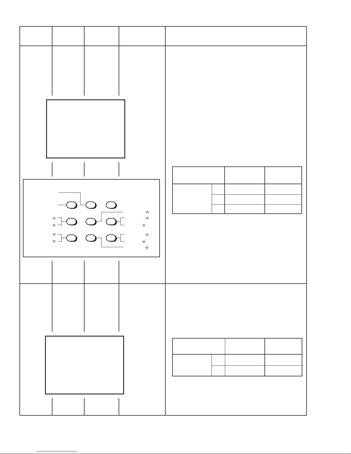
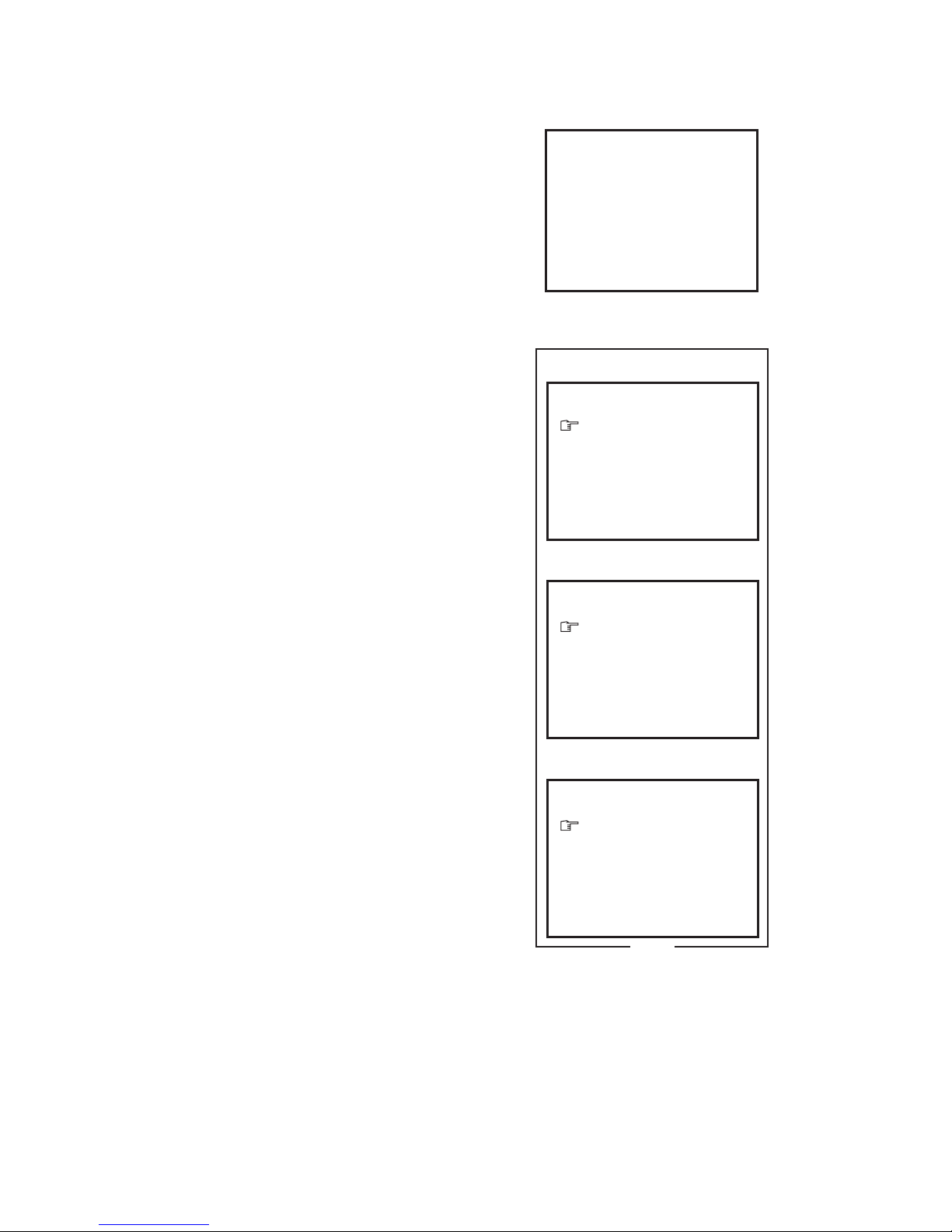
SYSTEM CONSTANT - I
SYSTEM CONSTANT SET 1/3
SYSTEM CONSTANT - II
SYSTEM CONSTANT SET 2/3
−/+: OPERATE DISP : EXIT
− / + : OPERATE DISP : EXIT
11. LANGUAGE : E/V
12. TUNER : MU
13. AMP TUNER : YES
14. VNR : NO
SYSTEM CONSTANT - III
SYSTEM CONSTANT SET 3/3
− / + : OPERATE DISP : EXIT
Fig. 2
a: SELECT
a: SELECT
a: SELECT
6. SPATIALIZER : YES
7. VOL. LIMITER : YES
8. B/B SOUND : NO
9. TEXT : NO
10. COLOUR AUTO : NO
1. INCH : 21
2. COLOUR : MULTI
3. VIDEO INPUT : 1
4. ECO SENSOR : YES
5. SUPER BASS : NO
REPLACEMENT OF MEMORY IC
1. MEMORY IC
This TV uses the following memory IC.
Memory IC: IC1702 on MAIN PW Board
The memory IC memorizes data for correctly operating the
video and deflection circuits. When replacing the memory IC,
be sure to use the same type IC written with the initial values
of data. In other words, use the specific IC listed in "PRINTED
WIRING BOARD PARTS LIST". For its mounting location, re-
fer to "ADJUSTMENT LOCATIONS".
2. PROCEDURE FOR REPLACING MEMORY IC
(1) Power off
Switch the power off and unplug the power cord from the
wall outlet.
(2) Replacing the memory IC
Replace the memory IC with new one. Be sure to use the
memory IC written with the initial data values.
(3) Power on
Plug the power cord into the wall outlet and switch the
power on.
(4) Check and setting of SYSTEM CONSTANT SET:
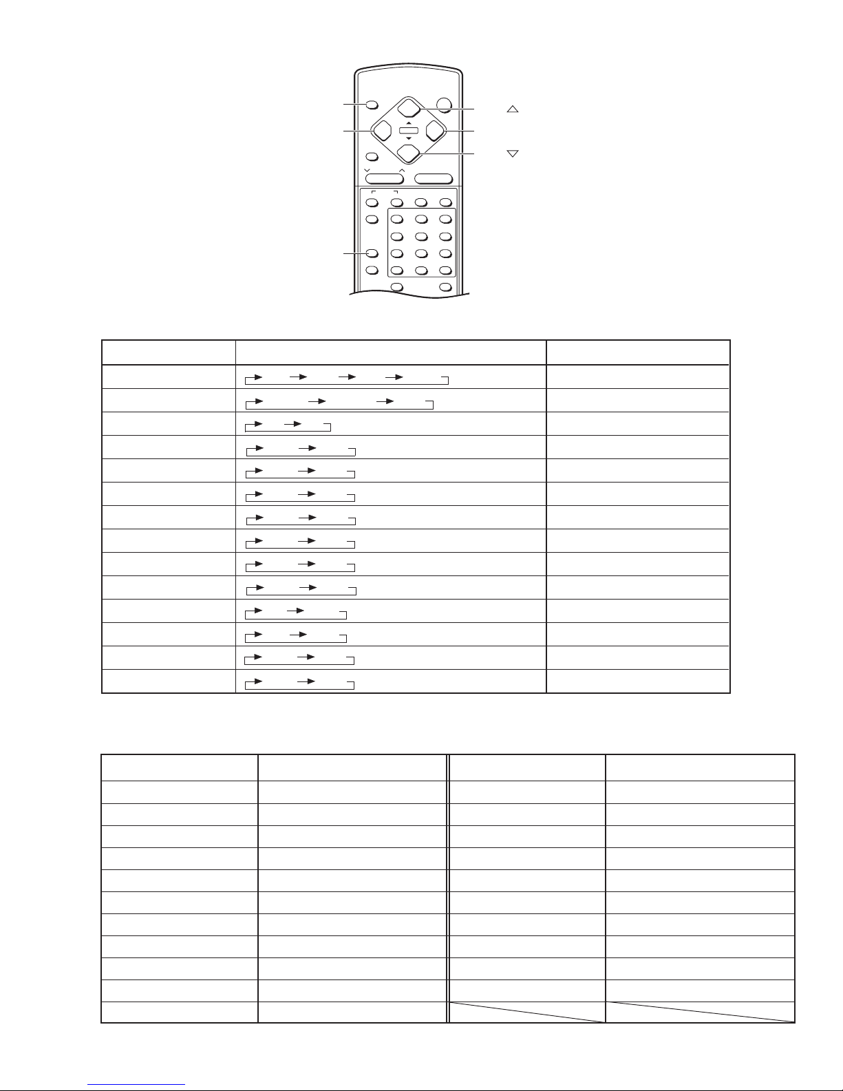
1) Press the DISPLAY key and the PICTURE MODE key
on the remote control unit simultaneously.
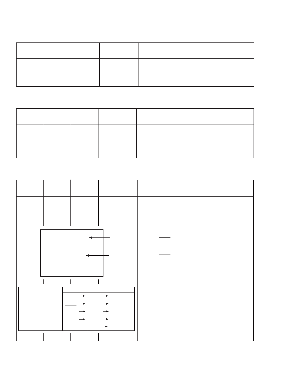
The SERVICE MENU screen will be displayed. (See
Fig. 1.)
2) In the SERVICE MENU, press the DISPLAY key and
PICTURE MODE key simultaneously. Then, the SYS-
TEM CONSTANT SET screen will be displayed. (See
Fig. 2.)
3) Check whether thesetting values ofthe SYSTEM CON-
STANT SET are the same as those indicated in Table
1. If the value is different, select the setting item with
the MENU akey, and set the correct value with
the MENU −/ +key.
4) Press the DISPLAY key twice to return to the normal
screen.
(5) Receive channel setting
Refer to the OPERATING INSTRUCTIONS and set the
receive channels (channels preset).
(6) User setting
Check the user setting values in Table 2, and if setting
value is different, set the correct value.
For setting, refer to the OPERATING INSTRUCTIONS.
(7) Setting of SERVICE MENU
Verify the setting for each setting item in the SERVICE
MENU. (See Table 3.) If readjustment is necessary, per-
form adjustment referring to "SERVICEADJUSTMENTS".
Fig. 1
SERVICE MENU
1. IF
3. VSM PRESET 2.V/C
SERVICE MENU
1-3 : SELECT DISP : EXIT
✽✽✽✽✽✽✽✽ ✽✽✽✽✽ ✽✽.✽✽✽✽
✽✽✽ ✽✽✽✽✽ ✽✽.✽✽✽✽