JVC AV-28BT8ENS User manual

No.52057
AV-28BT8ENS / AV-28BT8ENB / AV-28BT80EN
AV-28BT8EPS / AV-28BT8EPB / AV-28BT80EP
AV-28BT8EES / AV-28BT8EEB/ AV-28BS88EN
1COPYRIGHT © 2002 VICTOR COMPANY OF JAPAN, LTD.
Jul. 2002
AV-28BT8ENS / AV-28BT8ENB
AV-28BT80EN / AV-28BT8EPS
AV-28BT8EPB / AV-28BT80EP
AV-28BT8EES / AV-28BT8EEB
AV-28BS88EN
CONTENTS
!SPECIFICATIONS ・・・・・・・・・・・・・・・・・・・・
・・・・・・・・・・・・・・・・・・・・・・・・・・・・・・・・・・・・・・・・
・・・・・・・・・・・・・・・・・・・・ 2
!SAFETY PRECAUT IONS ・・・・・・・・・・・・・・
・・・・・・・・・・・・・・・・・・・・・・・・・・・・
・・・・・・・・・・・・・・4
!FEATURES・・・・・・・・・・・・・・・・・・・・・・・・・・
・・・・・・・・・・・・・・・・・・・・・・・・・・・・・・・・・・・・・・・・・・・・・・・・・・・・
・・・・・・・・・・・・・・・・・・・・・・・・・・5
!MAIN DIFFERENCE LIST ・・・・・・・・・・・・・・
・・・・・・・・・・・・・・・・・・・・・・・・・・・・
・・・・・・・・・・・・・・5
!SPECIFIC SERVICE INSTRUCTIONS ・・・・
・・・・・・・・
・・・・ 6
!SERVICE ADJUSTMENTS・・・・・・・・・・・・
・・・・・・・・・・・・・・・・・・・・・・・・
・・・・・・・・・・・・ 11
!PARTS LIST ・・・・・・・・・・・・・・・・・・・・・・・
・・・・・・・・・・・・・・・・・・・・・・・・・・・・・・・・・・・・・・・・・・・・・・
・・・・・・・・・・・・・・・・・・・・・・・ 23
★OPERATING INSTRUCTIONS
★STANDAR D CIRCUIT DIAGRAM ・・・・・・
・・・・・・・・・・・・
・・・・・・ 2- 1
SERVICE MANUAL
COLOUR TELEVISION

No.52057
A
V-28BT8ENS / AV-28BT8ENB / AV-28BT80EN
A
V-28BT8EPS / AV-28BT8EPB / AV-28BT80EP
A
V-28BT8EES / AV-28BT8EEB/ AV-28BS88EN
2
SPECIFICATIONS
Content
Item AV -2 8BT 8EN S
AV -2 8BT 8EN B
AV -2 8BT 8 0EN
AV -28 BT8 EPS
AV -28 BT8 EPB
AV - 28 BT 8 0E P
AV -28 BT8 EES
AV -28 BT8 EEB AV - 28BS8 8EN
Dimensions ( W×
××
×H×
××
×D ) 77 x 58 x 48 cm
Mass 33.2 kg
TV RF System B/G B/G , L /L ’ D/K , K1 B/G
TV Mode PAL PAL / SE CAM PAL / SE CAM PAL
Colour Sy st em
Video Mode PA L / SE C AM / NTSC 3 .58 / NTSC 4 .43 (E P/ EE M ODEL S)
PAL / NTSC 3.58 / NTSC 4.43 (EN MO DELS)
Sound System German + NICAM
Teletext System Fast ext / Topte xt
Receiving Frequency
VHF
(
VL
)
46 .25 MHz ~1 68. 25 MHz
(
VH
)
17 5.2 5MHz ~46 3.2 5MHz
UHF 47 1.2 5MHz ~86 3.2 5MHz
CATV S0 1-S4 1 & S7 5-S79
Intermediate Frequency
VIF Carrier 38.9 MHz (B/G , D/K , L) / 33.9MHz(L’)
SIF Car rier 33. 4 MHz (5 .5MHz:B/G) / 32. 9MHz (6.0MHz:D/ K ) / 32 .4MHz (6.5MHz: L) / 40.4MHz ( 6.5MHz:L’)
Colour Sub Carrier Fr eq.
PAL 4.43MHz
SE CAM 4.43MHz
NT SC 3.58MHz / 4.43MHz
Power Input AC 2 20V ~240V , 50Hz
Power Consumption 11 4W ( Max)
4W ( Sta nd by)
11 4W ( MA X)
4W ( Sta nd by)
11 4W ( MA X)
4W ( Sta nd by)
13 5W ( Max)
4W ( Sta nd by)
Aerial Input Term 75 Ωun ba lanc ed, Coaxial
Picture Tube Size Vi si ble si ze : 6 6cm , M eas ur ed di a gon all y
Hi g h Vo lt ag e 30 .3 kV 30 .3 kV 30 .3 kV 29 .6 kV
Spe ake r 5.7 cm ×16cm Oval type×2
Au dio Output 10 W ×2
Vide o 1V p- p, 75 Ω
S/V ideo Y : 1Vp- p Po sit ive
C : 0 .2 86V p- p
Input
Au dio
(
L/ R
)
50 0m Vrms, High Imp ed an ce
Vide o 1V p- p 7 5Ω
Output
Au dio
(
L/ R
)
50 0m Vrms, Lo w Im pe da nce
Rear Side AV 1 ( Vi d eo/A ud i o/RGB)
AV 2 ( Vid eo/A udio/S-VHS)
Input Terminal
Front Side AV 3 ( Vi d eo/A ud i o)
Front Side H ea dph on e j ac k (S ter e o m ini jack 3.5 φ)
Out
p
ut Terminal
Rear Side AV 1 ( Vi d eo/A ud i o)
AV 2 ( Vid eo/A ud io) (S elect ed TV,A V1 or AV 3)
Remote Control Unit VE -3 00 177 63 (R M- C 11 00) , (A A/R 0 6 d ry b at ter y×2)
Design & speci ficatio ns ar e su bje ct to cha nge wi thout no tice.

No.52057
A
V-28BT8ENS / AV-28BT8ENB / AV-28BT80EN
A
V-28BT8EPS / AV-28BT8EPB / AV-28BT80E
P
A
V-28BT8EES / AV-28BT8EEB/ AV-28BS88EN
3
■
■■
■21-pin Euro connector (SCART socket) : AV-1 / AV-2
(P-P= Peak to Peak, S-W= Sync tip to white peak, B-W= Blanking to white peak)
Pin
No . Signal Designation Matching Value AV-1 AV-2
1 AU DIO R o ut put 50 0m Vrms( Nom ina l),L ow i mpe dan ce ○
(TV OUT)
○
(TV/LINE OUT)
2 AUDIO R input 500mVrms(Nominal),High impedanc e ○○
3 AU DIO L o utp ut 50 0m Vrms( Nom ina l),L ow i mpe dan ce ○
(TV OUT)
○
(TV/LINE OUT)
4 AUDIO G ND ○○
5 GND (B) ○○
6 AUDIO L input 500mVrms(Nominal), High impedanc e ○○
7Binput 70 0m VB-W, 7 5Ω○
NC
8FUNCTON SW
(SLOW SW) Low : 0-3V, High : 8-12V, High impedance ○NC
9 GND (G) ○○
10 - NC -
11 G i n put 70 0m VB-W, 7 5Ω○
NC
12 -NC -
13 GND (R) ○○
14 GND (YS) ○NC
15 R / C input R : 700mVB-W, 75Ω
C : 300mVP-P , 75Ω
○
(R/C)
○
(only C)
16 Ys in put L ow : 0 – 0. 4, Hig h : 1 - 3 V, 75 Ω○NC
17 GND(VIDEO output) ○○
18 GND(VIDEO input) ○○
19 VIDEO ou tpu t 1V S-W (Negative going sync), 75Ω○
(TV)
○
(TV/LINE OUT)
20 VIDEO / Y input 1VS-W (Negative going sync), 75Ω○○
21 COMMON G ND ○○
[Pin assignment]

No.52057
A
V-28BT8ENS / AV-28BT8ENB / AV-28BT80EN
A
V-28BT8EPS / AV-28BT8EPB / AV-28BT80EP
A
V-28BT8EES / AV-28BT8EEB/ AV-28BS88EN
4
SAFETY PRECAUTIONS
1. The d esi gn of th is pr od uct con ta in s sp ecial har d wa re , ma ny
circuits and components specially for safety purposes. For
con tinu ed pr ot ecti on , n o chan g es sh ou ld b e ma de to the o rig inal
d esi gn un less a uth or ized i n w ritin g by th e ma nu fact ur er.
Rep lacem en t p ar ts m ust b e i d ent ic al to thos e u sed i n th e or igi n al
ci rcu it s. Se r vic e sh ou ld be pe rf or me d b y q ua li fie d per so nn el
on ly.
2. Al te r ati on s of t he desi g n or ci rcuitr y of t he pr od ucts sh oul d not be
made. Any design alterations or additions will void the
m anu fact ur er's w arr a nt y and wi ll f ur th er r eli eve t he ma nu factu r er
of r esp onsi b il ity for perso na l injur y or p rop er ty d am ag e resul t in g
th er efr om .
3. M an y e l ectr ical an d mech ani ca l p ar ts i n th e pr od ucts ha ve
special saf ety-related characteristics. T hese characteristics are
oft en no t e vi den t f r om vi sua l i nsp ection n or ca n t he pro tect io n
aff or de d by th em nece ssar ily b e ob tain ed b y u sin g rep l acem en t
com po ne nts ra ted f or hig he r vo l tag e, watt ag e, etc. Rep lacem en t
p arts wh ic h ha ve th ese sp eci al s afet y ch ar act er ist ics ar e
identified in the parts list of Servic e manual. El ec tric al
components having su ch features ar e identified by shading
on the sche matic s and by (!
!!
!) on the parts list in Service
manual. The us e of a sub sti tu te r ep la cem en t which do es n ot
h ave th e sam e saf ety ch ar act er ist ics as t he r eco mmen de d
r eplac em ent par t sh own i n th e p ar ts l ist of S er vi ce m an ual m ay
cause shock, fire, or other hazards .
4. Do n't shor t between the LIVE side ground and ISOL ATE D
(NEUTRAL) side ground or EARTH side ground when
repairing.
Some model's power circuit is partly different in the GND. The
diff er enc e of the GND i s sh own b y th e LI VE side G ND, th e
ISO LATE D(NEUTRAL) sid e GND a nd EA RTH side GND. Don't
sh ort b etw ee n the L IVE side GN D a nd IS OLATE D( NEUTRAL)
side GND or EA RTH side GND and ne ver meas ure with a
m easu r in g app ar atu s ( osc ill osc ope et c.) th e LIV E sid e GND an d
ISOLATED(NEUTRAL) side GND or EARTH side GND at the
same time.
If above note will not be kept, a fuse or any parts will be broken.
5. If any repair has been made to the chassis, it is recommended
th at t he B1 set ti ng shou l d b e ch ecke d or adj u ste d ( Se e
ADJU STMENT OF B 1 POW E R SUPPL Y).
6. The hi gh vol ta ge app lie d t o th e pictu r e tu be mu st con for m wit h
th at sp eci fi ed in S er vice m an ual. E xcessi ve h i gh vo lt ag e ca n
cau se an incr e ase in X- Ray em issi on , ar ci ng an d possi b le
component damage, therefore operation under excessive high
voltage conditions should be kept to a minimum, or should be
preve nt ed. If s evere arc ing occurs, remove t he AC power
immed iate l y an d de ter mine th e ca use b y visua l insp ect io n
( in cor rect in stal lat i on, cr acke d or m elte d hi gh vo lt age har n ess,
p oor so ld eri ng, et c.) . To m aint ai n the p r ope r min imu m l e vel of
sof t X- Ray emi ssion, c omp on en ts in th e hi gh voltag e cir cuitr y
incl ud ing t he pi ct ur e tu be must b e t he e xact r ep lacem e nts or
alte rn at ives ap pr ove d b y th e ma nuf act ur er of th e c om plet e
pr od uct.
7. Do n ot c hec k high volt ag e b y drawing an arc. Use a high volt ag e
m eter or a hi g h v oltag e pr ob e wit h a V T VM. D ischa rg e th e
picture tube before attempting meter connection, by connecting
a cl ip le ad to th e gr ou nd f ra me a nd c onn ecti n g th e oth er end of
the lead through a 10kΩ2W resi sto r to the an od e b utt on .
8. W hen se r vi ce is r equ ir e d, ob ser ve th e or igi na l lea d dr ess. E xtr a
pr ec aut i on sh ou ld b e g ive n t o assur e cor r ect l ea d dr ess i n th e
hig h voltag e cir cuit a r ea. W here a s hor t cir cui t h as occu rr e d,
th ose co mp on ent s tha t i ndica te evi de nce of ove r hea ting sho uld
b e r e place d. A l wa ys u se th e ma nuf act ur er 's r ep lacem en t
components.
9. Isolation Check
(Safety for Electrical Shock Hazard)
Af ter r e-ass emb lin g th e p r odu ct, al ways per f orm an i sol at io n
ch eck on the expo sed me tal p ar ts of t he cabin et ( a nte nn a
ter m ina ls, vid eo /au dio i npu t and ou tpu t t er mi n als, Con tr ol kn obs,
metal cabinet, screwheads, earphone jack , control shafts, etc.)
to be su re th e p r odu ct is s af e t o o pe r ate with ou t d an ger of
elect rical shoc k.
(1) Dielectric Strength Test
The iso l ati on be tw een the A C pr im a ry ci rcu i t an d all me tal p ar ts
exp ose d t o th e us er , p ar ti cular ly an y e xp os ed met al p art h avi ng a
r etu rn p ath to t he chass is sho uld withs tan d a volt age of 3 000 V
AC (r.m.s.) for a period of one second.
( . . . . W it hstan d a vo lt ag e of 1 10 0V A C ( r .m. s.) t o an ap pl ianc e
r ate d up to 12 0V , an d 3 00 0V AC ( r.m. s.) to an ap pli an ce r at ed
200V or more, for a periodof one second.)
This method of test requ ires a t est equipment not generally found
in t he servic e trad e.
(2) Leakage Current Check
Pl ug th e A C lin e c ord d ir ect l y in to th e A C ou tl et ( d o n ot use a lin e
isol ati o n tr ansf or m er du r in g thi s ch eck.) . Usi n g a " Lea kag e
Cur rent Teste r", me asur e th e l ea kag e cu rre nt f rom each exp osed
m etal p ar t of the ca bi ne t, p art icu lar ly any e xpos ed me tal p ar t
h aving a re turn pa th to t he ch assis , t o a kn own go od ea rt h
gr ou nd (wa ter pip e, e tc.) . An y l eaka ge cur ren t m ust n ot e xceed
0.5mA AC (r.m.s.).
Howeve r, i n tr op ic al area , th is mu st no t exce ed 0.2 mA AC
(r.m.s.).
"
""
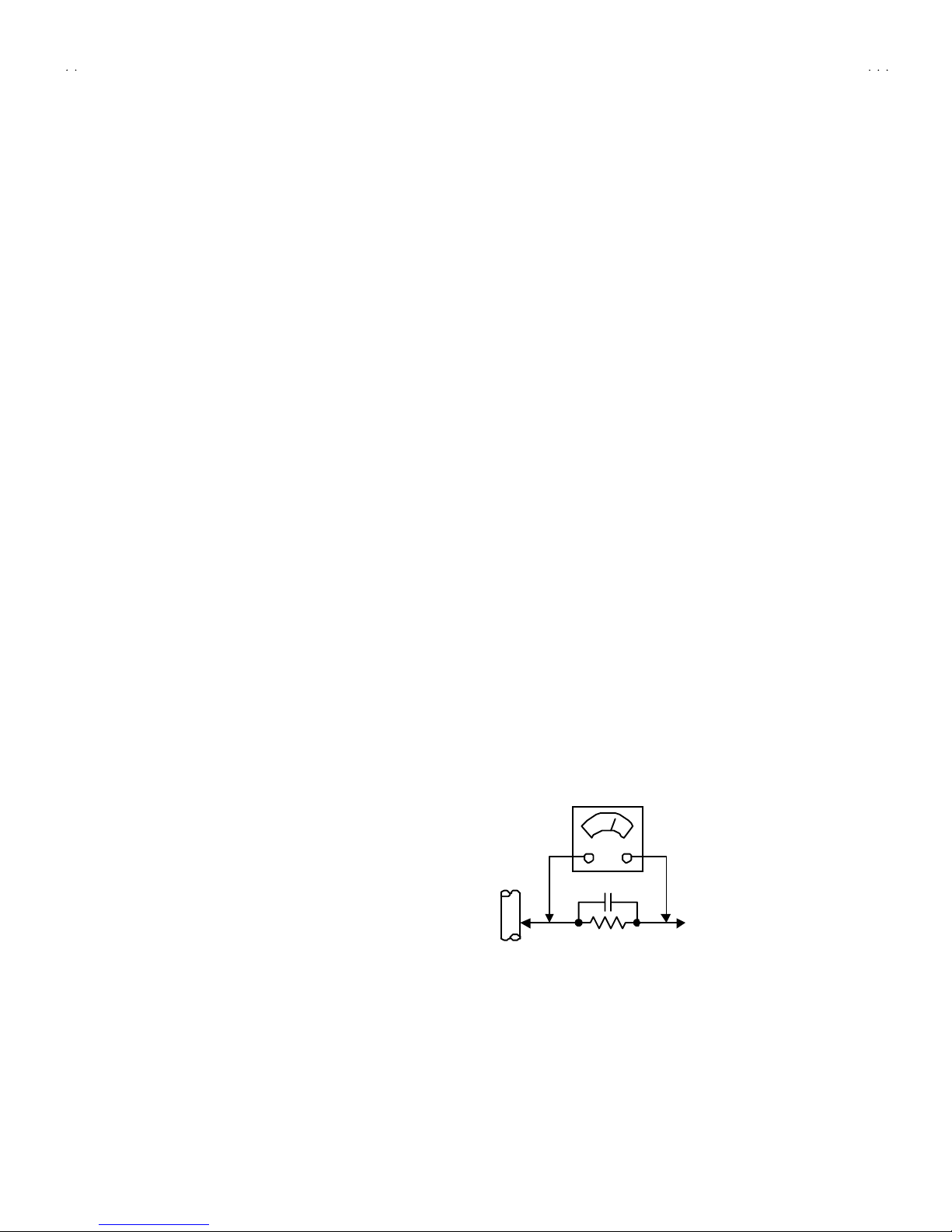
"Alte rnat e Ch e ck Met hod
Pl ug th e A C lin e c ord d ir ect l y in to th e A C ou tl et ( d o n ot use a lin e
isol ati o n tr an sfor mer dur ing t hi s che ck.) . Use an AC vo lt me ter
h avi ng 1 00 0 oh ms pe r volt or mor e sens it i vi ty in th e fo llow ing
m ann er. Con nec t a 1 50 0Ω10W res ist or par a ll e le d b y a 0 .1 5µF
AC -type c apa cit or bet we en an expo sed met al pa rt a nd a kno wn
g ood e ar th gr o un d ( wa ter pipe , etc.) . M eas ur e th e A C vo lt ag e
acr oss th e r es ist or wi th th e AC vo ltm eter . Move th e r esi stor
con nec ti on to e ach exp ose d me tal par t, p art icul arly a ny exp osed
m etal p ar t havi n g a retu rn pat h to t he ch assis, an d m easu r e th e
AC vol tag e ac ro ss the r es ist or . No w , re ver se th e plu g i n th e AC
ou tl et and r e pe at eac h m ea sur emen t. An y vol t ag e me asu re d
mu st not exc eed 0.75V AC (r.m. s.). This c orre sponds to 0.5mA
AC (r.m.s.).
However, in tropical area, this must not exce ed 0.3V AC ( r.m.s.).
This corresponds to 0.2mA AC (r.m.s.).
0.15μF A C-T YP E
1500 Ω10W
GOODEARTH GROUND
PLACE THIS PROBE
ON E A CH EX PO SE D
ME T AL PA R T
ACVOLTMETER
(HAVING 1000 Ω/V,
OR MOR E SENSIT IVITY)

No.52057
A
V-28BT8ENS / AV-28BT8ENB / AV-28BT80EN
A
V-28BT8EPS / AV-28BT8EPB / AV-28BT80E
P
A
V-28BT8EES / AV-28BT8EEB/ AV-28BS88EN
5
FEATURES
"10 0 pr o gram mers f r om V H F, U HF b and s or ca ble ch an nel s can
b e pr es et.
"It has t wo Euroconnector sockets for external devic es (such as
vi de o r eco rd er, vi d eo ga mes , a udio set, e tc.)
"St er eo s ou nd s ys tem s (Ni cam + Ger man ) ar e avail a ble.
"AP S ( Au tomat ic Progra mming Syst em)
MAIN DIFFERENCE LIST
!
!!
!
Model Name
Part Name
AV -2 8B T 8 ENS
AV -2 8B T 8 ENB
AV-2 8B T8 0EN
AV -2 8B T 8 EP S
AV -2 8B T 8 EP B
AV-2 8B T8 0EP
AV -2 8B T 8 EE S
AV -2 8B T 8 EE B AV-2 8B S8 8EN
MAIN PWB VE-20101577 VE-20101576 VE-20101622 VE-20101578
!INST RU CTION
BOOK VE-50028493 VE-50028296 VE-50028326 VE-50028511
!FRON T CABI NET
VE-20082289(ENS)
VE-20081489(ENB)
VE-20082289(EN)
VE-20082289(EPS)
VE-20081489(EPB)
VE-20082289(EP)
VE-20082289(EES)
VE-20081489(EEB) VE-20082289
!REAR COVER
VE-20084616(ENS)
VE-20069018(ENB)
VE-20084616(EN)
VE-20084616(EPS)
VE-20069018(EPB)
VE-20084616(EP)
VE-20084616(EES)
VE-20069018(EEB) VE-20086416
!LENS
VE-20069218
(
ENS/ENB
)
VE-20096162(EN)
VE-20069218
(
EPS/EPB
)
VE-20096162(EP)
VE-20069218 VE-20096162
!RATING LABEL
VE-20102137(ENS)
VE-20102147(ENB)
VE-20102144(EN)
VE-20101937(EPS)
VE-20101939(EPB)
VE-20101934(EP)
VE-20101919(EES)
VE-20101915(EEB) VE-20102141
CAR TON BOX
VE-50028496(ENS)
VE-50028502(ENB)
VE-50028500(EN)
VE-50028423(EPS)
VE-50028424(EPB)
VE-50028221(EP)
VE-50028218(EES)
VE-50028216(EEB) VE-50028498
CABINET COLOUR
Mo del Name FRONT CABINET & REAR COVER LENS
AV-28BT8ENS
AV-28BT8EPS
AV-28BT8EES
SILVER BLACK
AV-28BT8ENB
AV-28BT8EPB
AV-28BT8EEB
BLACK BLACK
AV-28BT80EN
AV-28BT80EP
AV-28BS88EP
SILVER SILVER

No.52057
A
V-28BT8ENS / AV-28BT8ENB / AV-28BT80EN
A
V-28BT8EPS / AV-28BT8EPB / AV-28BT80EP
A
V-28BT8EES / AV-28BT8EEB/ AV-28BS88EN
6
SPECIFIC SERVICE INSTRUCTIONS
DISASSEMBLY PROCEDURE
REMOVING THE REAR COVER
1. U np lu g t he po we r c or d.
2. Remove the 8 screws marked A as shown in t he Fig. 1.
3. Remove the 4 screws marked Baround the AV TERMINAL
BOA RD.
4. W ithdr a w t he r ear co ver to wa rd you .
REMOVING THE AV TERMINAL BOARD
"Removing the rear cover.
1. Remove th e 2 screws marke d C f asten ed th e AV TE RMINAL
BOA RD.
2. Remove th e AV TERMI NAL BOARD.
REMOVING THE MAIN PWB
"Removing the rear cover.
"Removing the AV TERMI NAL BOARD.
1. Remove th e 3 screws marked D as shown in t he Fi g.1 .
2. Sl ight l y r aise t he bo th si d es of th e ch assi s b y h and an d withd r aw
th e M AIN PW B ba ckwar d.
(If necess ary, take off the wire clamp, connectors etc.)
REMOVING THE SPEAKER
"Removing the rear cover.
1. Remove t he 4 screws marked E, and r em ove sp eake r as s h ow n
in Fig. 1.
2. R emove th e sp eake r .
REMOVING THE FRONT AV & HEADPHONE PWB
"Removing the rear cover.
"Removing the MA IN PWB.
1. Remove th e 2 screws marked F.
2. Remove th e FRONT AV & HE ADPHONE PWB.
REMOVING THE FRONT CONT ROL PWB
"After removing the rear cover .
1. R em ove th e MAIN PW B AS S’Y.
2. R emove th e 5screws marked G, a nd r em o ve th e FRO NT
CONTROL PWB.
CHECKING THE PW BOARD
To ch eck the b ack side of th e PW B oar d.
1) Pu ll o ut th e PW B oar d. ( Ref er to R EM OV IN G TH E MA IN
PW B ).
2) Er ect th e PW B oar d ve rt ic al ly so t ha t you c an easi ly ch eck
th e b ack si de of th e PW B oar d.
[CAUTION]
"When erecting the PW Board, be c areful so that there will be no
con tact in g with ot her PW Boar d.
"Be for e tur n in g on po w er, ma ke sur e t ha t the wi re co nn ecto r is
pr op erl y con nec ted .
"W hen co ndu cti ng a ch eck w ith p ow er su ppl ied , b e sur e to c onfi rm
th at t he CRT E ARTH W I RE (B RA IDED AS S’Y) is co nnected t o
th e C RT SOC KE T PW b oar d.
WIRE CLAMPING AND CABLE T YING
1. Be sure to clamp the wire.
2. N ever r emo ve th e c abl e ti e u sed f or t yi ng th e w ires to ge the r.
Sh oul d it be in adve rt ent l y r em ove d, b e su r e to ti e th e wir es w it h
a n ew c able tie.

No.52057
A
V-28BT8ENS / AV-28BT8ENB / AV-28BT80EN
A
V-28BT8EPS / AV-28BT8EPB / AV-28BT80E
P
A
V-28BT8EES / AV-28BT8EEB/ AV-28BS88EN
7
REAR COVER
SP EAKE R
MAIN PWB
FRONT CABINET
FRONT AV &
HEADPHONE PWB
(×4)
(× 8)
CRT
F
(× 2)
E
Fi
g
. 1
(×3)
D
A
(×4)
B
AV TERMINAL BOARD
BASE BOARD
G
(× 5)
FRONT CONTROL
PWB
C
(×2)
REAR SIDE
BB
AV TERMINAL BOARD

No.52057
A
V-28BT8ENS / AV-28BT8ENB / AV-28BT80EN
A
V-28BT8EPS / AV-28BT8EPB / AV-28BT80EP
A
V-28BT8EES / AV-28BT8EEB/ AV-28BS88EN
8
REPLACEMENT OF CHIP COMPONENT
!CAUTIONS
1. Avoid heating for more than 3 seconds.
2. D o n ot ru b t he el ect ro des an d t he r esi st p ar ts of th e p att er n.
3. W hen r emovi ng a c hip par t, m elt th e s ol der ad equ ate l y.
4. D o n ot r euse a ch i p p ar t afte r re mo vi ng it .
!SOLDERING IRON
1. Use a hig h ins ulatio n s older ing iron with a t hin pointed e nd of it .
2. A 3 0 w s older ing i ron is rec om mend ed for easi ly r emovi ng p arts.
!REPLACEMENT ST EPS
1. How to remove Chip parts
#
##
#Resi st ors, ca pa cit ors , etc
( 1) As sh own in t he f ig ure, pu sh th e pa rt with tw ee zer s and
alte rn at ely m elt th e sol de r at each en d.
( 2) Sh if t wi th tweeze rs an d r em o ve th e ch i p p ar t.
#
##
#Trans ist ors, d iod es , va ria bl e r es ist or s, et c
( 1) Ap pl y e xt ra so ld er to ea ch l e ad .
( 2) As sh own in t he f ig ure, pu sh th e pa rt with tw ee zer s and
alte rn at ely m elt th e sol d er a t each l e ad . S hi ft an d r emove t he
chip part.
Note : A fter removin g t he pa rt , remove remainin g solder from the
pattern .
2. How to install Chip parts
#
##
#Resi st ors, ca pa cit ors , etc
(1) Apply solder to the pattern as indic ated in the figure.
( 2) Gr asp t he ch i p p art with twee zer s and pl ac e i t on th e s ol d er.
The n h ea t an d me lt th e so ld er a t b oth en ds of t he chip par t.
#
##
#Trans ist ors, d iod es , va ria bl e r es ist or s, et c
(1) Apply solder to the pattern as indic ated in the figure.
( 2) Gr asp th e ch ip p art wit h t we eze rs an d p lace it on th e so l der.
(3) First s older lead Aas indicated in t he figure.
( 4) The n so ld er l e ads Band C.
SOLD E R SOLD E R
A
B
C
A
B
C

No. 52057
A
V-28BT8ENS / AV-28BT8ENB / AV-28BT80EN
A
V-28BT8EPS / AV-28BT8EPB / AV-28BT80E
P
A
V-28BT8EES / AV-28BT8EEB/ AV-28BS88EN
9
SERVICE MENU SELECT KEY
MEMORY IC REPLACEMENT
1. Memory IC
This model use a memory IC.
Thi s me mo r y I C st or es d ata for pr op er op er atio n of the vid eo
an d d ef l ecti on ci rcu it s.
When replacing, be sure to use an IC containing this (initial
value) data.
2. Memory IC rep lacement procedure
(1) Power off
Sw itch of f t he p ow er an d di scon nec t th e po we r co rd fr om
the wall outlet.
(2) Replace the memory IC
Init ial value must be entered into the n ew IC.
(3) Power on
Con nect th e po w er cor d t o t he wa ll o ut le t an d s witch on t he
power.
(4) SERVICE MENU setting
1) Press MENU key and, while the displayed MENU
screen, press 4, 7, 2, 5 key on th e r emote co ntr ol u nit or
press MUTING key and INFORMATION key at the
simultaneously.
2) The SER V IC E M ENU scr ee n of F ig.1 i s d isp l ayed .
3) Ve rif y wh at to set in th e SER V IC E M ENU, and set
what ever is n ece ssar y ( Fig.1 ). R ef er to th e SE RV ICE
ADJUSTMENT for setting.
4) Press the STANDARD key to exit SERVICE MENU.
(5) Receive channel setting
Refer to th e OP ERATING I NSTRUCTIO NS ( US ER’S
GU ID E) a nd s et th e r ece ive ch an nel s (C han n els P r eset ) as
described.
( 6) U ser se tting s
Check th e us er sett in g it em s acc or ding to aft er pa ge .
W here th ese d o no t a gree, r efer to t he OPE RA TIN G
INSTRUCT IONS (USER’S GUIDE) and set the it ems as
described.
Fig.1
SE RV ICE M ENU
Fig.2
VALUE
SELECT(-)
VALUE
SELECT(+)
NUMBER
ITEM
SELECT(▲)
ITEM
SELECT(▼)
MENU
FUNCTION
POWER
MU T I NG
INFORMATION
COLOUR
k
ey
STANDARD

No. 52057
A
V-28BT8ENS / AV-28BT8ENB / AV-28BT80EN
A
V-28BT8EPS / AV-28BT8EPB / AV-28BT80EP
A
V-28BT8EES / AV-28BT8EEB/ AV-28BS88EN
10
SETTING OF THE LAST MEMORY FOR SHIPMENT
■
■■
■USER SETTING VALUES
Setting Item Setting Value Setting Item Setting Value
SOUND MENU FEATURE MENU
BA LANCE CEN TER SL EEP TIME R OFF
BA SS ↑CHILD LOCK OFF
TREBL E ↑LA NG UA GE ENGL ISH
MODE STEREO AV-2 OUTPUT TV
EFFECT OFF
3D PANORAMA
(only A V- 28B S8 8EN) OFF
PICTURE MENU INSTALL
BRIGHTNESS PROGRAMME
CONTRAST BAND
COLOUR CHANNEL
SHAR PNES S SE ARCH
HUE (only NTSC)
Thes e ad just a re aut om atica lly
restored when AP S b it in Service
menu is set .
The pr oc edu r e f or se tting AP S
bit is described bellow. FINE TUNING
PICTURE MODE AUTO STORE
Refer to the INSTRUCTION
BOO K.
■
SETTING APS BIT IN SERVICE MENU
1) En ter ser vice me nu i n TV m ode b y pr essi ng “ IN FOR MA TION ” a nd “ M UT I NG” ke ys si mu l tan eou sl y. S er vic e M en u wi ll ap pea r.
2) Se le ct T X1 (TEL ET EXT OPTIO N) b y pr essi n g U p /D own keys o n r emot e c ontr o l un it.
3) Press the 7 key on remote c ontrol unit to set APS bit. (After this, bit 7 of TX1 will be “1”)
4) Press STANDARD key on remote control unit to exit service mode.
NOTE : DO NOT TURN OFF THE TV BY USING POWER BUTTON ON THE FRONT PANEL.

No. 52057
A
V-28BT8ENS / AV-28BT8ENB / AV-28BT80EN
A
V-28BT8EPS / AV-28BT8EPB / AV-28BT80E
P
A
V-28BT8EES / AV-28BT8EEB/ AV-28BS88EN
11
SERVICE ADJUSTMENTS
ADJUSTMENT PREPARATION
1. You ca n ma ke t he ne ce ssa ry adjust me nts f or t his un it wit h
either the Remote Control Unit or With the adjustment tools
and par ts as given below.
2. Ad justment with the Remote Control Unit is made on the
basis of the initial setting values, however, the new setting
values which set the screen to its optimum condition may
differ from the initial settings.
3. M ake sur e t hat AC p ower i s tu r ned o n c orrec tly.
4. T urn on th e pow er for s et an d test eq ui p me nt bef or e use , and
sta rt t he ad justm en t p r oced ur es aft er wai ting at l east 30 m in ut es.
5. U nless o the r wi se s pec if i ed, pr ep ar e t he mo st su it ab le r ecep ti on
or inp ut sign al for adj ust m ent.
6. N ever tou ch any ad j ustm en t p ar ts wh ic h ar e n ot sp ecified i n t he
list for this adjustment - variable resistors, transformers,
condensers, etc.
7. Pr es etti ng b efor e ad justm en t.
Unless ot her wi se spec if i ed in t he a djustm e nt i nstr uct i ons, p r ese t
th e f ol lo w in g f un cti ons with th e re mo te c ont ro l un it .
BRIGHTN ES S
CONTRAST
COLOUR
SHAR PNES S
CENTER
ADJUSTMENT EQUIPMENT
1. DC voltmeter (or digital voltmeter)
2. Sign al g en er at or (P att er n g en er at or) [PAL/SECAM/NTSC]
3. Remote control unit
ADJUSTMENT ITEM
!SCR EEN A DJUST MENT
!OSD HORIZONTAL PO SITION ADJ USTMENT
!IF ADJUSTMENT
!AGC A UTO MATI CA LL Y A DJUSTM ENT
!DEFLECTION CIRCUIT ADJUSTMENT
!GEO MET RY ME NU AD JUS TME NT
!WHITE BALANCE ADJUSTMENT
IC501
MI CO M
IC502
ME MO R Y IC
TUNER AV -1 AV -2
FBT
UPPER : FOCUS VR
LOWE R : SCREEN VR
V
O
L
(+)
(+)(+)
(+) (-)
(-)(-)
(-)
PROG
/Ch.
(+)
(+)(+)
(+) (-)
(-)(-)
(-)ME NU
LE D REMOCON
RECEIVER
FRONT
TOP
FRONT
AUDIO.
VIDEO RL
HEADPHONE J ACK
SCART
jack SCART
jack
MAIN PARTS LOCATIONS
FRONT AV & HEADPHONE PWB FRONT CONTROL PWB
MAIN PWB

No. 52057
A
V-28BT8ENS / AV-28BT8ENB / AV-28BT80EN
A
V-28BT8EPS / AV-28BT8EPB / AV-28BT80EP
A
V-28BT8EES / AV-28BT8EEB/ AV-28BS88EN
12
BASIC OPERATION SERVICE MENU
■
■■
■HOW TO ENT ER THE SERVICE MENU
1) Press the MENU key.
2) ME NU sc re en of fig.1 wi ll b e d i spla ye d
3) W hil e the ME NU scr ee n is di sp l ayed , p r ess th e 4,7 ,2, 5 ke y or
INFORMA TION key and MUT ING key s imu lt ane ously.
4) The SERVICE MENU screen of (Fig.2) will be displayed.
■SELECT ION OF ADJUSTMENT IT EMS
1) En ter th e SERVICE ME NU
2) Press the FUNCTION / key and select the ADJUSTMENT
ITEM.
3) Press the FUNCTION / ke y and s et t he SETTI NG VAL UE.
■HOW TO EXIT SERVICE MODE
1) Pr ess the ST ANDARD Key on REMOTE CONTROL UNIT.
■HOW TO ENTER T HE GEOMETRY MENU
"This model is built-in GEOMETRY MENU for geometry
adjustment.
1) En ter th e SERVICE ME NU
2) Press the GREEN key, geometry menu appears (Fig. 3).
3) Press the FUNCTION / key and select the ADJUSTMENT
ITEM.
4) Press the FUNCTION / ke y and s et t he SETTI NG VAL UE.
MENU SCRE EN
Fi
g
.1
"FUNCTION OF COLOUR key
RED key :
It sw itch es th e AV L t o ON o r OFF mo de on ser vic e
m enu . AV L wo rd i s vi si ble o n s er vi ce m en u wh en
AV L i s o n.
GR EE N k ey :
It s witch es t o GE OMETRY a djust menu . G eomet ry
of th e p ict ur e is a djust ed in th i s m enu .
YELLOW key :
It s witches t o VERT ICA L SCAN DISA BLE mode.
It is us eful t o a djust scr een vol t age .
BL UE ke y :
It is used to a dj ust AGC an d I F au tom a tical ly on
ser vice me nu.
REMOTE CONTROL UNIT key NAME
NUMBER key
FUNCTION
key
AV key MENU key
COLOUR k ey
STANDARD
key
MEN
U
SOUND
PICTURE
FEATURE
INSTALL
PROGRAM
SE RV ICE M ENU
Fi
g
.2
ADJUSTMENT ITEM SETTING VALUE
Fi
g
.3
VSIZ 023
VPOS 028
VSCO 000
VCCO 008
HSIZ 007
HPOS 039
HPIN 015
GEOME TRY
GEOME TRY MEN U
ADJUSTMENT ITEM SETTING VALUE
INFORMA TION
key

No. 52057
A
V-28BT8ENS / AV-28BT8ENB / AV-28BT80EN
A
V-28BT8EPS / AV-28BT8EPB / AV-28BT80E
P
A
V-28BT8EES / AV-28BT8EEB/ AV-28BS88EN
13
■ADJUSTMENT ITEM & INITIAL (Recommended) SETTING VALUE in the SERVICE MENU
1/2
ADJUSTMENT
ITEM DESCRIPTION INITIAL VALUE
OSD HORIZONTAL P OSI TION OF OSD 065
IF1 IF COARS E ADJUSTMENT 00 4
IF2 IF FINE ADJUSTMENT 065
IF3 IF COARS E ADJUSTMENT FOR L-P RI ME 00 4
IF4 IF FINE A DJUS TME NT FO R L-PRIME 065
AGC AUTOMATIC GA IN CO NT RO L Automat ic ally
VLIN VERTICA L LINEARITY Not used
RGBH RGB MODE HORIZONTAL SHIFT OFFSET 007
VSOF VERTICA L SIZE OFFSET for 60Hz -01 +05
(Only AV - 28B S88 )
VP OF VE RTICA L PO SITIO N OFFSET f or 60 Hz -01
HSOF HORIZONTAL SIZE OFFSET for 60Hz +00 -02
(Only AV - 28B S88 )
HPOF HORIZONTAL P OSI TION OFFSE T for 6 0Hz +00 -06
(Only AV - 28B S88 )
HTOF HORIZONTAL TRAPEZOID OFFSET for 60Hz +01 -03
(Only AV - 28B S88 )
W R WHITE PO INT ADJU STME NT FO R RE D 03 0
WG WHITE PO INT ADJUSTME NT FO R GREEN 03 0
WB WHITE PO INT ADJUSTMENT FO R BLUE 030
BR BIA S FOR R ED 02 8
BG BIA S FOR G RE EN 02 9
APR AUTOMATIC RGB P EAK REGULATION THRESHOL D 004
BRI BR IGHTNES S 03 2
CON CONTRAST 033
COL COLOUR 031
SHR SHARP 006
HUE HUE 031
VOL VOL UME 009
WR-R WHITE PO INT ADJUSTMENT for RED (RGBmo de) 022
W G-R WHITE PO INT ADJU STME NT for GREE N (R GBmo de) 03 2
WB-R WHITE PO INT ADJUSTMENT for BLUE (RGBmo de) 022
FMP 1 FM PRES CA LER W HE N AV L IS OFF Not used
NIP1 NICAM PRES CALE R W HE N AV L IS OFF Not used
SCP1 SCAR T PRES CA LER W HE N AV L IS OFF Not used
SE C1 SE CA M PRE SC ALE R W HE N AV L IS OFF Not used
FMP 2 FM PR ES CA LER W HE N AV L IS ON 01 5
NIP2 NICAM PRESCALER WHEN AVL IS ON 045
SCP2 SCAR T PRES CA LER W HE N AV L IS ON 01 7
SE C2 SE CA M PRE SCALE R W HE N AV L IS ON Not used
F1H HIGH BYTE OF VHF1-VHF3 CROSS-OVER FREQUENCY 00001001
F1L LOW BYTE O F VHF1-VHF3 CROSS -O VER FREQ UE NCY 1001 00 10
F2H HIGH BYTE OF VHF3-UHF CROSS-OVER FREQUENCY 00011011
F2L LOW BYTE O F VHF3-UHF C ROS S- OVER FREQ UE NCY 1000 00 10
BS 1 BA ND SW ITCHING B YTE FOR V HF1 0000 00 11
BS 2 BA ND SW ITCHING B YTE FOR V HF3 0000 01 10
BS 3 BA ND SW IT CH ING B YTE FOR U HF 10 00 01 01
CB CONTROL B YTE 10 00 11 10
OP1 PERIPHERAL OPTIONS 01110101

No. 52057
A
V-28BT8ENS / AV-28BT8ENB / AV-28BT80EN
A
V-28BT8EPS / AV-28BT8EPB / AV-28BT80EP
A
V-28BT8EES / AV-28BT8EEB/ AV-28BS88EN
14
2/2
ADJUSTMENT
ITEM DE SC RIPTI ON INITIAL VALUE
OP2 RECEPTI ON STANDARD OPTIO NS
00 00 10 01 (E N)
01 01 10 01 (E P)
00 01 10 01
(
EE
)
OP3 VIDEO OPTI ONS 01 10 11 00( EN)
11 10 11 00( EP /EE )
OP4 TV F E ATURE S 10 00 10 00
OP5 CHA NNE L T A BLES 00 00 00 0D
TX1 TEL ETEXT O PTIONS
11 01 01 01 (E N)
11 00 01 01 (E P)
11 00 11 01 (E E)
GEO M GEO MET RY OPTIO NS 00100000
OP8 PIP PRES ET CHANGE 00 00 01 00
[GEOMETRY MENU ]
INITIAL VALUE
ADJUSTMENT
ITEM DE SC RIPT I ON 4: 3 M O DE 16 :9 MOD E
VS IZ VE RTICA L S IZE f or 50 Hz 03 8 009
VP OS VE RTICA L PO SITIO N for 5 0Hz 02 2 02 5
VSCO VERTICAL S-CORRECTION for 50Hz 005 005
VCCO VERTICAL CORNER CORRECT ION for 50Hz 007 007
HSIZ HORIZONTAL SIZE for 50Hz 009 013
HPOS HORIZONTAL P OSI TION for 50Hz 030 030
HPIN HORIZONTAL PINCUSHION for 50Hz 014 012
HCCO HORIZONTAL CORNER CORRECTION for 50Hz 010 010
HTRP HORIZONTAL TRAPEZOID for 50Hz 013 018
VZSZ VERTICA L ZOOM SIZE f or 50Hz Not used Not used

No. 52057
A
V-28BT8ENS / AV-28BT8ENB / AV-28BT80EN
A
V-28BT8EPS / AV-28BT8EPB / AV-28BT80E
P
A
V-28BT8EES / AV-28BT8EEB/ AV-28BS88EN
15
ADJUSTMENTS
■
■■
■SC REEN ADJUSTMENT
Item Measuring
instrument Test point Ad justment part Description
SCREEN
adjust me nt
Remote
control unit
SCREEN VR
[On the FBT]
1. En ter SE RVIC E M ENU.
2. Pr ess YEL LOW ke y to di sab le ve rt ic al s can .
3. Ad ju st SCR EE N VR . on th e F BT a s th in as po ssib le.
4. Pr ess YEL LOW k ey ag ain to en able ver tical sc an.
5. Pr ess STANDARD key t o le ave s ervic e m enu.
■
■■
■OSD HOR IZONTAL POSITION ADJUSTMENT
Item Measuring
instrument Test point Ad justment part Description
HORIZONTAL
POS ITION O F
OSD
adjust me nt
Remote
control unit
OSD 1. En ter SE R VICE M ENU.
2. Sele ct OSD with FUNCTION ( / ) key
3. Adjust the OSD horizontal pos ition with the FUNCTION ( / )
key, wh ic h shi fts th e r ef er ence b ar o n the b ott om of th e
SE RV ICE M ENU ho r izo nta l ly, s o th at th e OSD i s po sition ed on
th e scr e en c ent er . ( X=X’)
■
■■
■IF ADJUSTMENT
Item Measuring
instrument Test point Ad justment part Description
IF adjustme nt Remote
control unit
IF 1
IF 2
IF 3
IF 4
1. R ecei ve a PAL colo ur ba r pat ter n .
2. En ter SE RVIC E M ENU.
3. Sele ct I F 1 with FUNCTION ( / ) ke y
4. Pr ess BLU E key d ur ing I F 1 i s h ig hl igh ted , I F 1 an d IF 2 va l ues
ar e ad ju sted au tom at ic al ly b y sof tw are.
5. If th e st and ar d i s L- p rim e, IF 3 and I F 4 valu es ar e ad ju stm ent
au tom at ic ally when B LUE key is pr ess ed dur in g I F 1 is
hig hlig ht ed.
FBT
FOCUS VR
SCREEN VR
R
e
f
e
r
e
n
ce
ba
r
Sc
r
ee
n
s
iz
e
SE RV ICE M ENU SCREEN
XX’

No. 52057
A
V-28BT8ENS / AV-28BT8ENB / AV-28BT80EN
A
V-28BT8EPS / AV-28BT8EPB / AV-28BT80EP
A
V-28BT8EES / AV-28BT8EEB/ AV-28BS88EN
16
■
■■
■AGC AUTOMAT ICALLY AD JUSTMENT
Item Measuring
instrument Test point Ad justment part Description
AG C
AUTOMATIC-
AL LY
adjust me nt
& check
Remote
control unit
AG C 1. En ter SE RVIC E M ENU.
2. Receive a 60dBμV R F sign al l eve l.
3. Sele ct AGC with th e FUNCTI ON ( / ) key.
4. Pr ess BLU E ke y on th e r emot e co ntr ol uni t.
5. Then the adjustment will be done automatically by software.
6. Se e th e AGC indi ca tor o n S ER VIC E MENU, it m ust b e “ 1” .
7. C heck th at p ict ur e is nor mal a t 90 dB μV signal level.
■
■■
■DEFLECTION CIR CUIT ADJUSTMENT
Item Measuring
instrument Test point Ad justment part Description
R GB M ODE
HORIZONTAL
SHIFT
OFFSET
adjus tme n t
Signal
gener ator
Remote
control unit
RGBH 1. Input R/G/B circle pattern signal via vid eo input termin al.
2. Press AV key on the remote control unit, force t he TV t o RGB
mode.
3. En ter SE RVIC E M ENU.
4. Sele ct RGBH with the FUNCTION ( / ) key.
5. Adju st RGBH wit h the FUNCTION ( / ) key until t he circle
p atter n is h or izo nt al ly ce nte r ed.( A=B)
6. C heck an d r ead ju st RGBH i tem i f th e adjus tme nt b eco mes
imp rope r aft er som e oth er g eomet ric a djust m ents ar e d on e.
VERTICAL
SIZ E OFFSET
adjus tme n t
(60Hz)
Signal
gener ator
Remote
control unit
VS OF 1. R ecei ve a N TSC -M cr oss- hat ch pa tte r n of ve rt ic al fr equ en cy
60Hz.
2. En ter SE RVIC E M ENU.
3. Sele ct VSOF with the FUNCTIO N ( / ) key.
4. Adjust VSOF with the FUNCTION ( / ) key until the
h orizo nt al blac k li nes o n b ot h t he u pp er a nd lower p ar t of th e
p atter n bec om e ver y clos e to t he u pp er a nd lowe r hor izon tal
si des of pi ctu re si ze a nd ne ar ly ab ou t to di sa pp ear .
5. Check and readjust VSOF item if the adjustment becomes
imp rope r aft er som e oth er g eomet ric a djust m ents ar e d on e.
:11
IF INDICATOR AGC INDICATOR NONE
SE RV ICE M ENU SCREEN
AB
Picture
size
10 0%
Scre en
size
Very clos e
Very clos e

No. 52057
A
V-28BT8ENS / AV-28BT8ENB / AV-28BT80EN
A
V-28BT8EPS / AV-28BT8EPB / AV-28BT80E
P
A
V-28BT8EES / AV-28BT8EEB/ AV-28BS88EN
17
Item Measurin
g
instruments Test
p
oint Ad justment part Description
VERTICAL
POSITION
OFFSET
adjus tme n t
(60Hz)
Signal
gener ator
Remote
control unit
VPOF 1. R eceive a N TSC-M ci rc l e p att er n of ve rtica l fr equ en cy 6 0Hz.
2. En ter SE RVIC E M ENU.
3. Sele ct VPOF with the FUNCTIO N ( / ) key.
4. Adjust VPOF with the FUNCTION ( / ) key until the
picturer is vertically centered.(C=D)
5. C heck an d r ead ju st ver tical positio n it em if t he a dj ust me nt
b ecom es i mpr op er aft er som e oth er ge om etr ic ad j ustm en ts
ar e do ne.
HORIZONTAL
POSITION
OFFSET
adjus tme n t
(60Hz)
Signal
Gene rator
Remote
control unit
HPOF 1. R eceive a N TSC -M ci rc le pat ter n si gn al of ver ti cal fr eq uen cy
60Hz.
2. En ter SE RVIC E M ENU.
3. Sele ct HPOF with the FUNCTION ( / ) key.
4. Adjust HPOF with the FUNCTION ( / ) key until the circle
p atter n is h or izo nt al ly ce nte r ed.( E=F)
5. C heck an d r ea djust a h ori zo nt al po sit ion it em if t he adj u stme nt
b ecom es i mp r ope r a fte r so me oth er ge ometr ic adj u stm en ts
ar e do ne.
HORIZONTAL
TRAPEZOI D
OFFSET
adjus tme n t
(60Hz)
Signal
Gene rator
Remote
control unit
HT OF 1. Recei ve a N TSC-M cr oss- h atch pa tter n si gn al of ve r tic al
fr eq ue ncy 6 0H z.
2. En ter SE RVIC E M ENU.
3. Sele ct HTOF with the FUNCTIO N ( / ) key.
4. Adju st HTOF with t he FUNCTIO N ( / ) key u ntil both
len gth s of th e up per sid e an d l o wer sid e of the closs- h atch
p atter n b ecom e equ al.
5. C heck an d r ead just HT OF p osi tion i te m if the ad j ust me nt
b ecom es i mp r ope r a fte r so me oth er ge ometr ic adj u stm en ts
ar e do ne.
C
D
EF
Screen
Vertical
Center
Pallalel

No. 52057
A
V-28BT8ENS / AV-28BT8ENB / AV-28BT80EN
A
V-28BT8EPS / AV-28BT8EPB / AV-28BT80EP
A
V-28BT8EES / AV-28BT8EEB/ AV-28BS88EN
18
■
■■
■GEOMETRY MENU ADJUSTMENT (Adjust 4:3MODE / 16:9MODE respectively)
Item Measurin
g
instruments Test point Ad justment part Description
VERTICAL
SIZ E
adjust me nt
(50Hz)
Signal
gener ator
Remote
control unit
VS IZ 1. R ecei ve a PA L B/G cr oss- h atch p att er n of ver ti ca l f r equ enc y
50Hz.
2. En ter SE R VICE M ENU.
3. Press the GREEN t hen enter th e GEOME TRY MENU.
4. Select VSIZ (Vertic al size) with the FUNCTION ( / ) key.
5. Adju st VSI Z with th e FUNCTION ( / ) key un til the
h or izon tal b lack li n es on bo th th e up per an d l o we r pa rt of the
p atter n bec om e ver y clos e to t he u pp er a nd lowe r h orizo nt al
si des of pi ctu r e size an d n ear ly a bo ut to d is ap pe ar.
6. C heck and r ea djust VS IZ item i f th e ad ju stm ent b ecom es
imp rope r aft er som e oth er g eomet ric a djust m ents ar e d on e.
VERTICAL
POSITION
adjus tme n t
(50Hz)
Signal
gener ator
Remote
control unit
VP OS 1. R eceive a PA L B/G ci rc le p att er n sig nal of ver t ic al f re qu enc y
50Hz.
2. Enter GEOMETRY MENU.
3. Se le ct VP OS ( Ver tica l posi ti o n) wit h t he FUNC TION ( / )
key.
4. Adju st VP OS wit h th e FUNCTION ( / ) ke y u ntil t he cir cle
pattern is vertically centered.(A=B)
5. C heck an d r ead just VP OS item if th e ad ju stm en t bec om es
imp rope r aft er som e oth er g eomet ric a djust m ents ar e d on e.
VERTICAL
S-CORRE C-
TION
adjus tme n t
(50Hz)
Signal
gener ator
Remote
control unit
VS CO 1. R eceive a PA L B/G cr oss- h atch p atte r n sign al of ver tica l
fr eq ue ncy 50H z.
2. Enter GEOMETRY MENU.
3. Se le ct VS CO ( Vertica l s-c orr ec ti on) wit h t he F UNCT ION
( / ) key.
4. Adjust VSCO wit h the FUNCTION ( / ) key until the vertical
len gth o f t he c ent er sq ua re r of th e cro ss- hat ch pat ter n
b ecom es equ al to up per a nd lower pa rt squ ar es of th e cr oss-
h atch pat ter n .
5. C heck an d r ead just VS CO i te m i f t he ad j ustm e nt bec om es
imp rope r aft er som e oth er g eomet ric a djust m ents ar e d on e.
A
B
Picture
size
10 0%
Scre en
size
Very clos e
Very clos e

No. 52057
A
V-28BT8ENS / AV-28BT8ENB / AV-28BT80EN
A
V-28BT8EPS / AV-28BT8EPB / AV-28BT80E
P
A
V-28BT8EES / AV-28BT8EEB/ AV-28BS88EN
19
Item Measuring
instrument Test point Ad justment part Description
VERTICAL
CORNER
CORRECTION
adjus tme n t
(50Hz)
Signal
gener ator
Remote
control unit
VCCO 1. Receive a PA L B/ G cross- hatch pat tern sign al of vertical
fr eq ue ncy 5 0H z.
2. Enter GEOMETRY MENU.
3. Select VCCO (Vertical s-correction) wit h t he FUNCTION
( / ) key.
4. Adju st VCCO with t he FUNCTION ( / ) key until the vertical
len gth o f th e up per a nd low e r p ar t squ ar es of t he cr oss -h atch
p atter n b ecom e equ al t o e ach ot her .
5. C heck and r ead just VCCO i te m if the adju stm ent b ecom es
imp rope r aft er som e oth er g eomet ric a djust m ents ar e d on e.
HORIZONTAL
SIZ E
adjus tme n t
(50Hz)
Signal
gener ator
Remote
control unit
HS IZ 1. Receive a PA L B/ G cross-h atch pat tern sign al of vertical
fr eq ue ncy 5 0H z.
2. Enter GEOMETRY MENU.
3. Sele ct HSIZ (Horiz ont al size) wit h the FUNCTION ( / ) key.
4. Adju st HSIZ with the FUNCTION ( / ) key until the vertical
blac k l in es o n b oth the l eft and r ight p ar t of th e cr oss-h atc h
pattern become very close to the left and right horizontal sides
of pictu r e tu be an d n ea rly a bo ut t o di sapp ea r .
HORIZONTAL
POSITION
adjus tme n t
(50Hz)
Signal
gener ator
Remote
control unit
HPOS 1. R eceive a PA L B/ G cir cle p atte rn sig nal o f ver ti ca l fr equ en cy
50Hz.
2. Enter GEOMETRY MENU.
3. Sele ct HPOS wit h th e FUNCTION ( / ) key.
4. Adju st HPOS with the FUNCTION ( / ) key u ntil the circle
p atter n is h or izo nt al ly ce nte r ed.( C=D)
5. C heck and r ea djust HPOS ite m if the adju stm ent b ecom es
imp rope r aft er som e oth er g eomet ric a djust m ents ar e d on e.
Picture size 100%
Screen size
Very clos e
Very clos e
CD

No. 52057
A
V-28BT8ENS / AV-28BT8ENB / AV-28BT80EN
A
V-28BT8EPS / AV-28BT8EPB / AV-28BT80EP
A
V-28BT8EES / AV-28BT8EEB/ AV-28BS88EN
20
Item Measuring
instrument Test point Ad justment part Description
HORIZONTAL
PINCUSHION
adjust me nt
(50Hz)
Signal
gener ator
Remote
control unit
HPIN 1. R eceive a PA L B/ G cr oss- h atch pat ter n si gn al of ve r tic al
fr eq ue ncy 5 0H z.
2. Enter GEOMETRY MENU.
3. Selec t HPIN (Hor iz ont al pincus hion ) wit h the FUNCTION
( / ) key.
4. Adju st HPIN with the FUNCTION ( / ) key until the bending
of the vertical line of the cross-hatch pattern are corrected.
5. C heck an d r ea djust HPIN item if th e adj u stm en t beco m es
imp rope r aft er som e oth er g eomet ric a djust m ents ar e d on e.
HORIZONTAL
CORNER
CORRECTION
adjust me nt
(50Hz)
Signal
gener ator
Remote
control unit
HCCO 1. Recei ve a PA L B/ G cr oss- h atch pat ter n sign al of ve r tic al
fr eq ue ncy 5 0H z.
2. Enter GEOMETRY MENU.
3. Select HCCO (Horizontal corner correction) with the
FUNCTION ( / ) key.
4. Adju st HCCO with t he FUNCTION ( / ) key until the b ending
of the vertical line of the cross-hatch pattern are corrected.
5. C heck a nd r ead ju st HC CO it em if t he a dj ust me nt b eco me s
imp rope r aft er som e oth er g eomet ric a djust m ents ar e d on e.
HORIZONTAL
TRAPEZOI D
adjust me nt
(50Hz)
Signal
gener ator
Remote
control unit
HT R P 1. R eceive a PA L B/ G cr oss- h atch pat ter n si gn al of ve r tic al
fr eq ue ncy 5 0H z.
2. Enter GEOMETRY MENU.
3. Se le ct H TR P (H ori zont al tr ap ezo id ) wit h t he F UNCTION
( / ) key.
4. Adjust HTRP with the FUNCTION ( / ) key until both lengths
of th e u pp er sid e an d l ower side of th e cr oss- hatc h pa tte r n
b ecom e equ al.( A=B)
5. C heck and r e adjust HT RP i te m if th e a djust me nt b eco me s
imp rope r aft er som e oth er g eomet ric a djust m ents ar e d on e.
Screen
Vertical
Center
A
B
This manual suits for next models
8
Table of contents
Other JVC TV manuals

JVC
JVC AV-32S585 User manual

JVC
JVC AV 27D302 User manual

JVC
JVC AV-28KH1BUF System manual

JVC
JVC AV-2168TEE User manual

JVC
JVC AV-29FH1BUGC Quick start guide

JVC
JVC AV-27320 User manual

JVC
JVC I Art PRO AV-48P777 Administrator Guide

JVC
JVC AV32T25EKS User manual

JVC
JVC TM-2001U User manual

JVC
JVC AV-2100QE User manual

JVC
JVC PD-42DX User manual

JVC
JVC AV-21F9 User manual

JVC
JVC C-N21102/S User manual

JVC
JVC LT-43C870(A) User manual

JVC
JVC AV-14AMG3, AV-14FMG3, AV-20NMG User manual

JVC
JVC AV21BT7EPS User manual

JVC
JVC I' Art AV-27F802 User manual

JVC
JVC InteriArt AV-28X4SU User manual

JVC
JVC AV-27F703 - 27" Real Flat TV User manual

JVC
JVC AV-28NH4SU User manual