JVC HV-L34PRO User manual

No.51809
HV-L34PRO
1COPYRIGHT © 2001 VICTOR COMPANY OF JAPAN, LTD. Jul. 2001
HV-L34PRO
HV-L34PRO/HK
HV-L34PRO/-A
HV-L34PRO/AU
HV-L34PRO/EE
CONTENTS
!SPECIFICATIONS ・・・・・・・・・・・・・・・・・・・・
・・・・・・・・・・・・・・・・・・・・・・・・・・・・・・・・・・・・・・・・
・・・・・・・・・・・・・・・・・・・・ 2
!SAFETY PRECAUTIONS ・・・・・・・・・・・・・・
・・・・・・・・・・・・・・・・・・・・・・・・・・・・
・・・・・・・・・・・・・・ 3
!MAIN DIFFERENCE LIST ・・・・・・・・・・・・・・
・・・・・・・・・・・・・・・・・・・・・・・・・・・・
・・・・・・・・・・・・・・ 4
!FEATURES・・・・・・・・・・・・・・・・・・・・・・・・・・
・・・・・・・・・・・・・・・・・・・・・・・・・・・・・・・・・・・・・・・・・・・・・・・・・・・・
・・・・・・・・・・・・・・・・・・・・・・・・・・ 4
!FUNCTIONS・・・・・・・・・・・・・・・・・・・・・・・・・
・・・・・・・・・・・・・・・・・・・・・・・・・・・・・・・・・・・・・・・・・・・・・・・・・・
・・・・・・・・・・・・・・・・・・・・・・・・・ 6
!SPECIFIC SERVICE INSTRUCTIONS・・・・
・・・・・・・・
・・・・ 8
!SERVICE ADJUSTMENTS・・・・・・・・・・・・
・・・・・・・・・・・・・・・・・・・・・・・・
・・・・・・・・・・・・ 14
!PARTS LIST ・・・・・・・・・・・・・・・・・・・・・・・
・・・・・・・・・・・・・・・・・・・・・・・・・・・・・・・・・・・・・・・・・・・・・・
・・・・・・・・・・・・・・・・・・・・・・・ 37
★
OPERATING INSTRUCTIONS
★
STANDARD CIRCUIT DIAGRAM・・・・・・・
・・・・・・・・・・・・・・
・・・・・・・ 2-1
SERVICE MANUAL
COLOUR TELEVISION
BASIC CHASSIS
MF

No. 51809
HV-L34PRO
11
REPLACEMENT OF MEMORY ICs
1. Memory ICs
This TV use memory ICs. In the memory ICs, there are memorized data
for correctly operating the video and deflection circuits. When replacing
memory ICs, besure to use ICs written with the initial values of data.
2. Procedure for replacing memory ICs
(1) Power off
Switch the power off and unplug the power cord from the wall outlet.
(2) Replace ICs.
Be sure to use memory ICs written with the initial data values.
(3) Power on
Plug the power cord into the wall outlet and switch the power on.
(4) Check and set SYSTEM CONSTANT SET:
*
**
*
It must not adjust without signal.
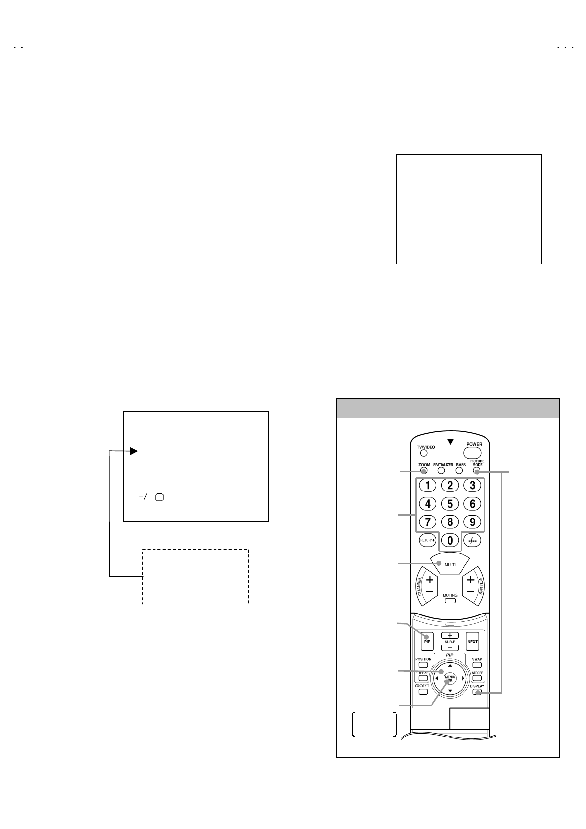
1) Press the DISPLAY key and the PICTURE TUBE key of the REMOTE CONTROL UNIT simultaneously.
2) The SERVICE MENU screen of Fig. 1 will be displayed.
3) While the SERVICE MENU is displayed, press the DISPLAY key and PICTURE TUBE key simultaneously, and the SYSTEM
CONSTANT SET screen of Fig. 2 will be displayed.
4) Check the setting values of the SYSTEM CONSTANT SET of Table 1. If the value is different, select the setting item with the
FUNCTION UP/DOWN key, and set the correct value with the FUNCTION -/+ key.
5) Press the MENU(OK) key to memorize the setting value.
6) Press the INFORMATION key, and return to the normal screen.
(5) Setting of receive channels
Set the receive channel.
For setting, refer to the OPERATING INSTRUCTIONS.
(6) Setting of SERVICE MENU
Verify the setting items of the SERVICE MENU of Table 2, and
reset where necessary.
For setting, refer to the SERVICE ADJUSTMENTS.
(7) User settings
Check the user setting values of Table 3, and if setting value is
different, set the correct value.
For setting, refer to the OPERATING INSTRUCTIONS.
SERVICE MENU
1. IF 2. V/C
3. AUDIO 4. DEF
5. VSM PRESET 6. STATUS
7. PIP 8. WB PRESET
9. SHIPPING(OFF) 0. BUS FREE
1-0 : SELECT DISP : EXIT
Fig.1
SYSTEM CONSTANT SET
+ : STORE DISP : EXIT
1. TEXT
**
OK
Fig.2
2. BLUE BACK MENU
3. E.M.C
4. WHITE BACK
5. COLOUR AUTO
6. PICTURE TILT
**
**
**
**
**
PICTURE
CONTENTS
key
PIP key
MENU/OK key
FUNCTION key
(UP/DOWN &
LEFT/RIGHT key)
SETTING ITEM
SELECT key
(Numbers key)
SERVICE
MENU/
&SYSTEM
CONSTANT
key
MEMORY
(STORE)
key
SERVICE MENU KEY
ZOOM
(ASPECT)
key

No. 51809
HV-L34PRO
12
SETTING VALUES OF SYSTEM CONSTANT SET (TABLE 1)
MODEL No.
Setting item HV-L34PRO HV-L34PRO/-A HV-L34PRO/HK HV-L34PRO/AU HV-L34PRO/EE
1. TEXT YES YES NO YES YES
2. BLUE BACK MUTE NO ↑↑
NO NO
3. E. M. C ↑NO ↑↑↑
4. WHITE BACK ↑↑↑↑↑
5. COLOUR AUTO ↑YES ↑↑↑
6. PICTURE TILT YES ↑YES YES YES
SERVICE MENU SETTING ITEMS (TABLE 2)
Setting item Setting value Setting item Setting value
1. IF 1. VCO
2. ATT ON / OFF 5. VSM PRESET
BRIGHT
STANDARD
SOFT
1. CONT.
2. BRIGHT
3. SHARP
4. COLOUR
5. TINT
2. V / C 1. RGB BLK
2. WDR R
3. WDR G
4. WDR B
5. BRIGHT
6. CONTRAST
7. COLOUR
8. TINT
9. SHARP
10. VCO ADJ.
11. VID ADJ.
12. SYNC SLICE
13. A MOVIE
6. STATUS
(Do not adjust) 1. SOFT
2. TELETEXT
3. ASPECT
3. AUDIO
(Do not adjust) 1. ERR LIMIT
2. A2 ID THR
3. QUASI
7. PIP 1. PIP VCO ADJ
2. PIP VID AGC
3. PIP SYNC SLICE
4. DEF. 1. V-SHIFT
2. V-SIZE
3. H-CENT
4. H-SIZE
5. TRAPEZ
6. EW-PIN
7. COR-PIN
8. COR-UP
9. COR-LO
10. ANGLE
11. BOW
12. V-S.CR
13. V.LIN
14. V.BLK-UP
8. WB PRESET 1. WDR R
2. WDR G
3. WDR B

No. 51809
HV-L34PRO
13
USER SETTING VALUES (TABLE 3)
Setting item Setting value Setting item Setting value
MAIN POWER SW OFF SUB POWER ON
SHIPPING CHANNEL PR1 DISPLAY INDICATED
PRESET CHANNEL See ; OPERATING
INSTRUCTIONS. VOLUME LEVEL 10
PICTURE SETTING INSTALL
PICTURE MODE BRIGHT LANGUAGE ENGLISH
WHITE MODE COOL EDIT "PRESET CHANNEL ONLY
ECO MODE OFF "OTHER : NON (SPACE)
PICTURE FEATURES FEATURES
DIGITAL VNR AUTO SLEEP TIMER OFF
DIGIPURE PRO AUTO BLUE BACK ON
COLOUR SYSTEM "TV : Depends on PR/CH AUTO SHUT OFF OFF
"EXT : AUTO VIDEO-3 SETTING COMPONENT
ZOOM REGULAR CHILD LOCK OFF (for all the channels)
PICTURE TILT CENTER CHANNEL GUARD ALL CH : OFF
SOUND
BASS CENTER BEE ON
TREBLE CENTER SUPER BASS ON
BALANCE CENTER AI VOLUME ON
SPATIALIZER OFF

No. 51809
HV-L34PRO
14
SERVICE ADJUSTMENTS
BEFORE STARTING SERVICE ADJUSTMENT
1. There are 2 ways of adjusting this TV: One is with the
REMOTE CONTROL UNIT and the other is the conventional
method using adjustment parts and components.
2. The setting (adjustment) using the REMOTE CONTROL
UNIT is made on the basis of the initial setting values. The
setting values which adjust the screen to the optimum
condition can be different from the initial setting values.
3. Make sure that connection is correctly made to AC power
source.
4. Turn on the power of the TV and measuring instrument for
warming up for at least 30 minutes before starting adjustment.
5. If the receive or input signal is not specified, use the most
appropriate signal for adjustment.
6. Never touch parts (such as variable resistors, transformers and
condensers) not shown in the adjustment items of this
service adjustment.
7. Preparation for adjustment (presetting):
Unless otherwise specified in the adjustment items, preset the
following functions with the REMOTE CONTROL UNIT:
"Setting position
PICTURE MODE (VSM) STANDARD
SLEEP TIMER OFF
BALANCE CENTER
ECO OFF
ZOOM REGULAR
MEASURING INSTRUMENT AND FIXTURES
1. DC voltmeter (or digital voltmeter)
2. Oscilloscope
3. Signal generator (Pattern generator) [PAL / SECAM / NTSC]
4. Remote control unit
ADJUSTMENT ITEMS
●Checking items.
●Adjustment of FOCUS.
●VSM preset setting.
●VIDEO / CHROMA circuit adjustment.
●DEFLECTION circuit adjustment.
●AUDIO circuit adjustment. (Do not adjust)

No. 51809
HV-L34PRO
15
ADJUSTMENT LOCATIONS
MAIN PWB POWER&DEF PWB
WDEG
1pin:B1(TP-91)
2pin:NC
3pin:X-RAY
4pin:X-RAY
5pin:GND
5
1
X
FRONT CONTROL PWB (R)
FRONT
HV
CN014
FRONT CONTROL PWB (L)
HVT
MICON PWB
100Hz PWB
ANT-IN
FRONT
FRONT
HEAD
PHONE
J
F
CH DOWN
MENU/
OK
CH UP
IN (VIDEO-4)
R4 L4 V4 S IN
TV/VIDEO EXT
VOL UP
VOL DOWN
F901
Power cord
POWER SW
ECO SPETIALIZER
C901
LF901
CDS
Speaker
SYNC
PWB
TUNER 2
CN003
CN007
CN013
C1
CN001
CN004
CN005
CN006
TUNER
F
F. CONT.(L) PWB
S
IN
R3
CN002
CN111
CN002
To AV SW PWB
TOP
AV SW PWB
SCREEN
VR
FOCUS 1
VR
CRT SOCKET
PWB
(SOLDER SIDE)
VM
VR
FOCUS-2
TP-E
TP-47B
VM
CN013
TP-Y
CN014
E1
CRT
YV
(VR1)
XV COIL
YHC
(VR2)
FRONT
PW
WJ
FRONT
BLK PWB
POWER

No. 51809
HV-L34PRO
16
BASIC OPERATION SERVICE MENU
1. TOOL OF SERVICE MENU OPERATION
Operate the SERVICE MENU with the REMOTE CONTROL UNIT.
2. SERVICE MENU ITEMS
With the SERVICE MENU, various settings (adjustments) can be made, and they are broadly classified in the following items of settings
(adjustments):
(1) 1. IF ・・・・・・・・・・・・・・・・・・・・・・・・・・・・・・ This mode adjusts the setting values of the IF circuit.
(2) 2.V/C ・・・・・・・・・・・・・・・・・・・・・・・・・・・・・ This mode adjusts the setting values of the VIDEO / CHROMA circuit.
(3) 3.AUDIO ・・・・・・・・・・・・・・・・・・・・・・・・・・ This mode adjusts the setting values of the SOUND circuit. (Do not adjust)
(4) 4.DEF・・・・・・・・・・・・・・・・・・・・・・・・・・・・・ This mode adjusts the setting values of the DEFLECTION circuit for each aspect mode given
below.
(5) 5.VSM PRESET ・・・・・・・・・・・・・・・・・・・・ This mode adjusts the initial setting values of Bright, Standard & soft.
(VSM : Video Status Memory)
(6) 6.STATUS・・・・・・・・・・・・・・・・・・・・・・・・・ It is no requirement to adjustment.
(7) 7.PIP ・・・・・・・・・・・・・・・・・・・・・・・・・・・・・ This mode adjusts the setting values of the PIP circuit. (PIP : Picture In Picture)
(8) 8.WB PRESET ・・・・・・・・・・・・・・・・・・・・・ This mode adjusts the setting values of the WHITE BALANCE.
(9) 9.SHIPPING(OFF) ・・・・・・・・・・・・・・・・・・ This mode adjusts the setting values of the channel presettings.
If you turn the SHIPPING position set ON.
This setting becomes channel presetting automatically.
Also you turn theTV power off, this setting become OFF position automatically.
(10) 0.BUS FREE・・・・・・・・・・・・・・・・・・・・・・ It is not requirement to adjustment.
ZOOM (ASPECT) V. FREQ.
REGULAR 100Hzi / 60HzP
ZOOM ↑
16 : 9 ↑

No. 51809
HV-L34PRO
17
3. BASIC OPERATION OF SERVICE MENU
(1) How to enter SERVICE MENU
Press the PICTURE MODE key and the DISPLAY key of the
REMOTE CONTROL UNIT simultaneously, and the SERVICE
MENU screen of Fig. 1 will be displayed.
(2) Selection of SUB MENU SCREEN
Press one of keys 1~0 of the REMOTE CONTROL UNIT and
select the SERVICE MENU SCREEN (See Fig. 3), form the
SERVICE MENU.
SERVICE MENU →SUB MENU
1. IF
2. V / C
3. AUDIO (Do not adj.)
4. DEF.
5. VSM PRESET
6. STATUS (Do not adj.)
7. PIP
8. WB PRESET
9. SHIPPING (OFF)
0. BUS FREE
SERVICE MENU
SERVICE MENU
1. IF 2. V/C
3. AUDIO 4. DEF
5. VSM PRESET 6. STATUS
7. PIP 8. WB PRESET
9. SHIPPING(OFF) 0. BUS FREE
1-0 : SELECT DISP : EXIT
Fig.1
PICTURE
CONTENTS
key
PIP key
MENU/OK key
FUNCTION key
(UP/DOWN &
LEFT/RIGHT key)
SETTING ITEM
SELECT key
(Numbers key)
SERVICE
MENU/
&SYSTEM
CONSTANT
key
MEMORY
(STORE)
key
SERVICE MENU KEY
ZOOM
(ASPECT)
key

No. 51809
HV-L34PRO
18
SERVICE MENU SCREEN
BRIGHT
STANDARD
SOFT
1. RGB BLK
2. WDR R
3. WDR G
4. WDR B
5. BRIGHT
6. CONTRAST
7. COLOUR
8. TINT
9. SHARP
10. VCO ADJ
11. VID AGC
12. SYC SLI
13. A MOVIE
1. ERR LIMIT
2. A2 ID THR
3. QUASI
Fig. 3
3. AUDIO (Do not adjust)
DEF REGULAR
***
******
***
Hz
1. V-SHIFT
4. DEF
****
(
****
)
- / + : STORE DISP : EXIT
OK
1. V-SHIFT
2. V-SIZE
3. H-CENT
4. H-SIZE
5. TRAPEZ
6. EW-PIN
7. COR-PIN
8. COR-UP
9. COR-LO
10. ANGLE
11. BOW
12. V-S.CR
13. V.LIN
14. V.BLK-UP
1. CONT.
2. BRIGHT
3. SHARP
4. COLOUR
5. TINT
V/C
1. RGB. BLK
****
2. V/C
PAL
AUDIO
1. ERR LIMIT
***
C _ AD _ BITS =
********
5. VSM PRESET
VSM PRESET STD
1.CONT
***
- / + : STORE DISP : EXIT
OK
WB PRESET
***
******
***
1. WDR R
**
8. WB PRESET
- / + : STORE DISP : EXIT
OK
PIP
1. PIP VCO ADJ
***
7. PIP
- / + : STORE DISP : EXIT
OK
AUTO
- / + : STORE DISP : EXIT
OK
1. PIP VCO ADJ
2. PIP VID AGC
3. PIP SNC SLI
6. STATUS (Do not adjust)
STATUS
1. SOFT
***
- / + : STORE DISP : EXIT
OK
1. SOFT
2. TELETEXT
3. ASPECT
- / + : STORE DISP : EXIT
OK
1. WDR R
2. WDR G
3. WDR B
IF SERVICE MENU
1. VCO
2. ATT ON / OFF
1-2 : SELECT DISP : EXIT
1. IF (CW)
VCO (CW)
***
******
***.
..
.**
****
**
MHz
MAIN SUB
TOO HIGH
ABOVE REF
JUST REF
BELOW REF
TOO LOW DISP : EXIT
IF ATT ON/OFF
**
****
**
- / + : STORE DISP : EXIT
OK
SERVICE MENU
SERVICE MENU
1. IF 2. V/C
3. AUDIO 4. DEF
5. VSM PRESET 6. STATUS
7. PIP 8. WB PRESET
9. SHIPPING(OFF) 0. BUS FREE
1-0 : SELECT DISP : EXIT
(ON or OFF)
SUB MENU

No. 51809
HV-L34PRO
19
(3) Method of Setting
"Method of Setting 1.IF
[VCO] ・・・・・・・・・・・・・・・・・・・・・・・・・・・ *It must not adjust without signal
①1 Key・・・・・・・・・・・・・・・・・・・・・・・・・ Select 1.IF.
②1 Key ・・・・・・・・・・・・・・・・・・・・・・・・ Select 1. VCO (CW)
Check the arrow position between the ABOVE REF. and BELOW REF.
③2 Key・・・・・・・・・・・・・・・・・・・・・・・・・ Select 2.ATT ON/OFF (Strong Electric Field : ON / Generally Electric Field : OFF)
④DISPLAY(DISP) Key・・・・・・・・・・・・ Return to the SERVICE MENU screen.
"Method of setting 2.V/C, 4.DEF, 5.VSM PRESET, 7.PIP and 8.WB PRESET.
①2, 4, 5, 7 & 8 Key・・・・・・・・・・・・・・・ Select one from 2. V/C, 4. DEF, 5. VSM PRESET, 7.PIP & 8.WB PRESET.
②FUNCTION UP/DOWN Key・・・・・・ Select setting items.
③FUNCTION -/+・・・・・・・・・・・・・・・・・ Set (adjust) the setting values of the setting items.
④MENU (OK) Key ・・・・・・・・・・・・・・・ Memorize the setting value.
(Before storing the setting values in memory, do not press the CH, TV, POWER ON / OFF key -
if you do, the values will not be stored in memory.)
⑤DISPLAY (DISP) Key ・・・・・・・・・・・ Return to the SERVICE MENU screen.
"3. AUDIO, 6. STATUS, 9. SHIPPING(OFF) & 0. BUS FREE.
It is not requirement to adjustment.
(4) Release of SERVICE MENU
1) After completing the setting, return to the SERVICE MENU, then again press the DISPLAY (DISP) key.

No. 51809
HV-L34PRO
20
ADJUSTMENT
CHECKING ITEM
Item Measuring
instrument Test point Adjustment part Description
Check of B1
Power Supply Signal
Generator
DC voltmeter
Remote
Control unit
TP-91(B1)
TP-E(#
##
#)
[X connector
on POWER
DEF PWB]
1. RGB BLK 1. Receive any broadcast.
2. Press the ZOOM key and select the FULL mode.
3. Select 2. V/C from the SERVICE MENU.
4. Select 1. RGB BLK with function UP / DOWN key.
5. Press the function ( ) key to find the cut off screen (Black
screen).
6. Connect a DC voltmeter to TP-91(B1) and TP-E(#).
7. Make sure that the voltage is DC139.9 ±2.0V.
8. Press the function ( ) key to return to service menu.
Check of High
Voltage Signal
Generator
DC volunteer
Remote
Control unit
CRT anode
Chassis GND
1. RGB BLK 1. Receive any broadcast.
2. Press the ZOOM key and select the FULL mode.
3. Select 2. V/C from the SERVICE MENU.
4. Select 1. RGB BLK with function UP / DOWN key.
5. Press the function ( ) key to find the cut off screen (Black
screen).
6. Connect a DC voltmeter to CRT ANODE and chassis GND.
7. Make sure that the voltage is DC 32.0kV .
8. Press the function ( ) key to return to service menu.
*Remove the probe before removing the earth clip.
Check of VCO Remote
control unit 1. VCO
2. ATT ON/OFF
"Under normal conditions, no adjustment is required.
"Confirmation adjustment.
1. Select 1.IF from the SERVICE MENU.
2. Then select 1.VCO from the IF SERVICE MENU.
3. Receive any broadcast.
4. Check the MAIN arrow ( ) position between the ABOVE REF.
and BELOW REF.
5. Press the MENU (OK) key and receive any broadcast with PIP
Button.
6. Check the SUB arrow ( ) position between the ABOVE REF
and BELOW REF.
*The arrow ( ) position means AFC voltage level.
*2. ATT ON/OFF : Generally Electric Field : OFF
: Strong Electric Field : ON
*Change the MAIN and SUB by MENU/OK key .
+1kV
-1.5kV
TOO HIGH
ABOVE REF
JUSTREF
BELOW REF
TOO LOW
DISP : EXIT
VCO
(
CW
)
****
MHz
MAIN SUB
1. VCO
2. ATT ON/OFF
DISP : EXIT
IF SERVICE MENU
1-2 : SELECT

No. 51809
HV-L34PRO
21
ADJUSTMENT OF FOCUS & SCREEN
Item Measuring
instrument Test point Adjustment part Description
Adjustment of
FOCUS Signal
generator FOCUS 1 VR(In HVT)
FOCUS 2 VR
(IN CRT SOCKET PWB)
1. Receive a cross-hatch signal.
2. Press the ZOOM key and select the regular mode.
3. By turning the FOCUS 1 VR, adjust the to make the vertical
lines as fine and sharp as possible.
4. By turning the FOCUS 1 VR, adjust the picture so that the 5th
vertical line from left side of the cross-hatch picture becomes
thinnest.
5. By turning the FOCUS 2 VR(In CRT SOCKET PWB), adjust
the 3rd horizontal line from the upper side may become
uniform at the line center and its periphery.
6. Carry out adjustment by repeating the steps 3, 4 and 5 about.
7. Make sure that the screen is darkened, the lines remain in
good focus.
Adjustment of
SCREEN VR Signal
generator SCREEN VR
(In HVT) 1. Receive a whole black signal .
2. Press the ZOOM key and select the regular mode.
3. Select 2. V/C from the SERVICE MENU.
4. Rotate the SCREEN VR (In HVT) clockwise(from 1→0→1)
from the full counterclockwise slowly and stop it at the point
where “CLOW” status (marked in Fig.) changes from 1 to
0 (which is indicated at the 3rdcolumn from the right.).
*“CLOW” : control loopout of window.
V/C
1. RGB _ BLK
00
SERVICE MODE SCREEN
CLOW
status
0 0 0 0 0 1 0 0
PAL
- / + : STORE DISP : EXIT
OK
1
SCREEN VR
FOCUS 1 VR
HVT
FOCUS 1 VRFOCUS 2 VR
1
2
3
12345

No. 51809
HV-L34PRO
22
VSM PRESET SETTING
Item Measuring
instrument Test point Adjustment part Description
Setting of
VSM PRESET Remote
control unit 1.CONT.
2. BRIGHT
3. SHARP
4. COLOUR
5. TINT
1. Select 5.VSM PRESET from the SERVICE MENU.
2. Select STD with the PICTURE MODE key of the remotecontrol
unit.
3. Adjust the function UP/DOWN and LEFT/RIGHT key to bring
the set values of 1.CONT ~5. TINT to the values shown in
the table.
4. Press the MENU/OK key and memorize the set value.
5. Respectively select the VSM PRESET mode for REGULAR
and BRIGHT, and make similar adjustment as in 3 above.
6. Press the MENU/OK key and memorize the set value.
#Refer to OPERATING INSTRUCTIONS for the PICTURE
MODE.
Setting item
VSM preset mode 1. CONT. 2. BRIGHT 3. SHARP 4. COLOUR 5. TINT
BRIGHT +16 0 -10 +3 0
STANDARD +7 0 -10 0 0
SOFT 00-12-20
SETTING VALUES OF VSM PRESET

No. 51809
HV-L34PRO
23
Setting item
Colour system
Setting item
Colour system
VIDEO/CHROMA CIRCUIT ADJUSTMENT
The setting (adjustment) using the REMOTE CONTROL UNIT is made on the basis of the initial setting values.
The setting values which adjust the screen to the optimum condition can be different from the initial setting values.
Initial setting value Initial setting value
PAL SECAM NTSC PAL SECAM NTSC
RGB BLK 8.TINT 000
2.WDR R 000 9.SHARP +007
3.WDR G 000 10.VCO ADJUSTMENT Automatically optimized
after adjustment
4.WDR B -010 11.VID AGC 000
5.BRIGHT 000 12.SYC SLI +007
6.CONTRAST 000 13.A MOVIE +001
7.COLOUR 000 000 000
Item Measuring
instrument Test point Adjustment part Description
Adjustment
of WHITE
BALANCE
(High-Light)
Signal
generator
Remote
control unit
2.WDR R
3.WDR G
"Set the PICTURE MODE to COOL.
1. Receive a black and white signal (colour off).
2. Select 2. V/C from the SERVICE MENU.
3. Modify 2. WDR R and 3.WDR G data to adjust the white
balance ( high light ).
4. Press the MENU/OK key and memorize the set value.
5. Change the contrast and brightness with the remote control up
& down from low–light to high–light and check that the tracking
of the white balance is good.
Adjustment
of
SUB BRIGHT
Remote
control unit 5.BRIGHT 1. Receive any broadcast.
2. Select 2.V/C from the SERVICE MENU.
3. Select 5.BRIGHT with the function UP/DOWN key.
4. Set the initial setting value with the function LEFT/RIGHT key.
5. If the brightness is not the best with the initial setting value,
make fine adjustment until you get the best brightness.
6. Press the MENU/OK key and memorize the set value.
Adjustment
Of SUB
CONTRAST.
Remote
control unit 6.CONTRAST 1. Receive any broadcast.
2. Select 2.V/C from the SERVICE MENU.
3. Select 6.CONTRAST with the function UP/DOWN key.
4. Set the initial setting value with the function LEFT/RIGHT
key.
5. If the contrast is not the best with the initial setting value, make
fine adjustment until you get the best contrast.
6. Press the MENU/OK key and memorize the set value.
"marked %:Do not adjust
%
%%
%
%

No. 51809
HV-L34PRO
24
Item Measuring
instrument Test point Adjustment part Description
7.COLOUR
(PAL/SECAM/NTSC) [Method of adjustment without measuring instrument]
(PAL COLOUR)PAL COLOUR
1. Receive PAL broadcast.
2. Select 2.V/C from the SERVICE MENU.
3. Select 7.COLOUR with the function UP/DOWN key.
4. Set the initial setting value for PAL COLOUR with the function
LEFT/RIGHT key.
5. If the colour is not the best with the initial set value, make fine
adjustment until you get the best colour.
6. Press the MENU/OK key and memorize the set value.
(SECAM COLOUR)SECAM COLOUR
1. Receive a SECAM broadcast.
2. Make fine adjustment of SECAM COLOUR in the same
manner as for above.
(NTSC 3.58 COLOUR)
1. Input a NTSC 3.58MHz COMPOSITE VIDEO signal from the
EXT terminal.
2. Make similar fine adjustment of NTSC 3.58 COLOUR in the
same manner as for above.
(NTSC 4.43 COLOUR)
Adjustment
of SUB
COLOURⅠ
ⅠⅠ
Ⅰ
Remote
control unit
NTSC COLOUR
1. Receive a NTSC 4.43MHz COMPOSITE VIDEO signal from
the EXT terminal.
2. Make similar fine adjustment of 4.43 COLOUR in the same
manner as for above.
PICTURE
CONTENTS
key
PIP key
MENU/OK key
FUNCTION key
(UP/DOWN &
LEFT/RIGHT key)
SETTING ITEM
SELECT key
(Numbers key)
SERVICE
MENU/
&SYSTEM
CONSTANT
key
MEMORY
(STORE)
key
SERVICE MENU KEY
ZOOM
(ASPECT)
key

No. 51809
HV-L34PRO
25
Item Measuring
instrument Test point Adjustment part Description
7.COLOUR
(PAL/SECAM/NTSC) [Method of adjustment using measuring instrument]
(PAL COLOUR)PAL COLOUR
1. Receive a PAL full field colour bar signal(75% white).
2. Select 2.V/C from the SERVICE MENU.
3. Select 7.COLOUR with the function UP/DOWN key.
4. Set the initial setting value of PAL COLOUR with the function
LEFT/RIGHT key.
5. Connect the oscilloscope between TP-47B and TP-E
6. Adjust PAL COLOUR and bring the value of (A) in the
illustration to 0V (voltage difference between white (w) and
blue (B)).
7. Press the MENU/OK key and memorize the setting value.
(SECAM COLOUR)SECAM COLOUR
1. Receive a SECAM full field colour bar signal(75% white).
2. Select 2.V/C from the SERVICE MENU.
3. Select 7.COLOUR with the function UP/DOWN key.
4. Set the initial setting value of SECAM COLOUR with the
function LEFT/RIGHT key.
5. Adjust SECAM COLOUR and bring the value of (A) of the
illustration to –6V(W~B).
6. Press the MENU/OK key and memorize the setting value.
(NTSC 3.58 COLOUR)
1. Input a NTSC 3.58MHz COMPOSITE VIDEO signal (full field
colour bar with 75% white) from the EXT terminal.
2. Select 2.V/C from the SERVICE MENU.
3. Select 7.COLOUR with the function UP/DOWN key.
4. Set the initial setting value of NTSC 3.58 COLOUR with the
function LEFT/RIGHT key.
5. Adjust NTSC 3.58 COLOUR and bring the value of (A) of the
illustration to -5V(W~B).
6. Press the MENU/OK key and memorize the setting value.
(NTSC 4.43 COLOUR)
Adjustment
of SUB
COLOUR Ⅱ
ⅡⅡ
Ⅱ
Signal
generator
Oscilloscope
Remote
control unit
TP-47B
TP-E(#
##
#)
[CRT
SOCKET
PWB ]
NTSC COLOUR
1. Input a NTSC 4.43MHz COMPOSITE VIDEO signal (full field
colour bar with 75% white) from the EXT terminal.
2. Select 2.V/C from the SERVICE MENU.
3. Select 7.COLOUR with the function UP/DOWN key.
4. Set the initial setting value of NTSC 4.43 COLOUR with the
function LEFT/RIGHT key.
5. Adjust NTSC 4.43 COLOUR and bring the value of (A) of the
illustration to -5V(W~B).
6. Press the MENU/OK key and memorize the setting value.
(+)
(-)
0
WCy Mg B
(A)

No. 51809
HV-L34PRO
26
Item Measuring
instrument Test point Adjustment part Description
8.TINT [Method of adjustment without measuring instrument]
(NTSC 3.58 TINT)NTSC 3.58 TINT
1. Input a NTSC 3.58MHz COMPOSITE VIDEO signal (full field
colour bar with 75% white) from the EXT terminal.
2. Select 2.V/C from the SERVICE MENU.
3. Select 8.TINT with the function UP/DOWN key.
4. Set the initial setting value of NTSC 3.58 TINT with the function
LEFT/RIGHT key.
5. If you cannot get the best TINT with the initial setting value,
make fine adjustment until you get the best TINT.
6. Press the MENU/OK key and memorize the set value.
(NTSC 4.43 TINT)
Adjustment
of
SUB TINT
Remote
control unit
NTSC 4.43 TINT
1. When NTSC 3.58 is set, NTSC 4.43 will be automatically set at
the respective values.
8.TINT [Method of adjustment using measuring instrument]
(NTSC 3.58 TINT)NTSC 3.58 TINT
1. Input a NTSC 3.58MHz COMPOSITE VIDEO signal (full field
colour bar with 75% white) from the EXT terminal.
2. Select 2.V/C from the SERVICE MENU.
3. Select 8.TINT with the function UP/DOWN key.
4. Set the initial setting value of NTSC 3.58 TINT with the function
LEFT/RIGHT key.
5. Connect the oscilloscope between TP-47B and TP-E
6. Adjust NTSC 3.58 TINT to bring the value of (B) in the
illustration to -12V (voltage difference between white (W) and
magenta(Mg)).
7. Press the MENU/OK key and memorize the setting value
(NTSC 4.43 TINT)
Adjustment
of
SUB TINTⅡ
ⅡⅡ
Ⅱ
Signal
generator
Oscilloscope
Remote
control unit
TP-47B
TP-E(#
##
#)
[CRT
SOCKET
PWB]
NTSC 4.43 TINT
1. When NTSC 3.58 is set, NTSC 4.43 will be automatically set at
the respective values.
[For main picture]
1. Input a PAL full field colour bar signal (75% white) from EXT
terminal.
2. Select 2. V/C from the SERVICE MENU.
3. Then Select 10. VCO adjustment with the function UP/DOWN
key.
4. Press the MENU/OK key.
*When the MENU/OK key is pressed, VCO for colour decoder
will be automatically set at the respective values.
Adjustment
of VCO
for colour
decoder
Signal
generator
Remote
control unit
10. VCO
[For PIP]
5. Select 7.PIP from the SERVICE MENU.
6. Then select 1.PIP VCO ADJ with the function UP/DOWN key.
*When the MENU/OK key is pressed, VCO for colour decoder
will be automatically set at the respective values.
0
WCy Mg B
(B)
(+)
(-)

No. 51809
HV-L34PRO
27
DEF. CIRCUIT ADJUSTMENT
There are 3 aspect modes ( ①
①①
①REGULAR, ②
②②
②ZOOM & ③
③③
③16 : 9) of the adjustment ( 1 ) 100Hz i mode, ( 2 ) 60Hz p and ( 3 ) 120Hz i
mode ・
・・
・・・・・
・・・・・・・・
・・・・・
・・
・depending upon the kind of signals ( vertical frequency 100Hzi / 60HZp / 120Hzi ).
"When the 100Hz REGULAR mode has been established, the setting of other modes will be done automatically.
However, if the picture quality has not been optimized, adjust each mode again, respectively.
"The adjustment using the remote control unit is made on the basis of the initial setting values.
"The setting values which adjust the screen to the optimum condition can be different from the initial setting values.
Initial setting value
REGULAR ZOOM 16 : 9
Setting item
100Hz i 60Hz p 100Hz i 60Hz p 100Hz i 60Hz p
1. V- SHIFT -3 +8 0 0 0 0
2. V-SIZE +5 0 0 0 -15 0
3. H-CENT -11 +3 0 0 0 0
4. H-SIZE -11 -5 0 0 -3 +3
5. TRAPEZ -16 +17 0 0 0 0
6. EW-PIN -36 0 0 0 0 0
7. COR-PIN 0 0 0 0 0 0
8. COR-UP 0 0 0 0 0 0
9. COR-LO -10 0 0 0 0 0
10. ANGLE 0 0 0 0 0 0
11. BOW 0 0 0 0 0 0
12. V-S.CR +5 00000
13. V-LIN -6 +4 0 0 0 0
14. V.BLK-UP 80 0 0 0 -94 -10
: Do not move.
FIXED VALUE

No. 51809
HV-L34PRO
28
Item Measuring
instrument Test point Adjustment part Description
Adjustment
of
V-SHIFT
Signal
generator
Remote
control unit
1.V- SHIFT [REGULAR mode]
1. Receive a circle pattern signal of vertical frequency 50Hz.
2. Select 4.DEF from the SERVICE MENU.
3. Select 1.V-SHIFT with the function UP/DOWN key.
4. Adjust V-SHIFT to make A = B.
5. Check the adjustment value above in other zoom mode.
If it is a wrong adjustment, re-adjust in ZOOM mode and
adjust by 1. V-SHIFT and 13.V-LIN.
6. Press the MENU/OK key and memorize the set value.
Adjustment
of V-SIZE 2.V-SIZE 7. Receive a cross-hatch signal.
8. Select 2.V-SIZE and set the initial setting value.
9. Adjust V-SIZE and make sure that the vertical screen size of
the picture size is in the bellow table.
10. Press the MENU/OK key and memorize the set value.
11. Input a NTSC VIDEO signal (60Hz) from the EXT terminal,
and make sure that the vertical screen size is in the below
table.
12. Press the MENU/OK key and memorize the set value.
A
B
Screen size
Picture size 100%
Picture
size
100%
Screen
size
ZOOM
REGULAR ZOOM 16 : 9
TOP 92% (FIXED) (FIXED)
BOTTOM 92% (FIXED) (FIXED)
[ SCREEN SIZE ]
SCREEN
POSITION
ASPECT

No. 51809
HV-L34PRO
29
Item Measuring
instrument Test point Adjustment part Description
Adjustment of
H. CENTER Signal
generator
Remote
control unit
3.H-CENT. 13. Receive a circle pattern signal.
14. Select 3.H-CENT and set the initial setting value.
15. Adjust H-CENT to make C=D.
16. Press the MENU/OK key and memorize the set value.
Adjustment
of
H.SIZE
4.H-SIZE 17. Receive a cross-hatch signal.
18. Select 4.H-SIZE and set the initial setting value.
19. Adjust H-SIZE and make sure that the horizontal screen size
of the picture size is in the bellow table.
20. Press the MENU/OK key and memorize the set value.
21. Input a NTSC VIDEO signal (60Hz) from the EXT terminal, and
make sure that the horizontal screen size is in the below table.
22. Press the MENU/OK key and memorize the set value.
Adjustment of
EW-PIN 6.EW-PIN 23. Select 6.EW-PIN and set the initial setting value
24. Adjust EW-PIN and make the 2nd.vertical lines at the left and
right edges of the screen straight. Also make sure that the 3rd
vertical lines are straight.
25. Press the MENU/OK key and memorize the set value.
CD
Straight
ZOOM
ASPECT
MODE
ADJ. ITEM REGULAR ZOOM 16 : 9
H-SIZE 92% (FIXED) (FIXED)
This manual suits for next models
4
Table of contents
Other JVC TV manuals

JVC
JVC AV21BF5ENS User manual

JVC
JVC TM-2001U User manual

JVC
JVC AV-20N3 User manual

JVC
JVC InteriArt AV-28R47SK User manual

JVC
JVC RM-C326 User manual

JVC
JVC AV14BJ8EES User manual

JVC
JVC AV-28R370KE User manual

JVC
JVC LT19D200 - 19" LCD TV User manual

JVC
JVC C-13310/S User manual

JVC
JVC LT-26B60BU User manual

JVC
JVC AV-21RT4BU User manual

JVC
JVC AV-16N311 User manual

JVC
JVC AV-36260 User manual

JVC
JVC PD-42V31BJE User manual

JVC
JVC AV-21L41/BK User manual

JVC
JVC AV-14FT Use and maintenance manual

JVC
JVC LT-32WX84 User manual

JVC
JVC AV-N48P55 User manual

JVC
JVC AV-20F703 User manual

JVC
JVC AV-29ED5BN, AV-29ED5SN User manual