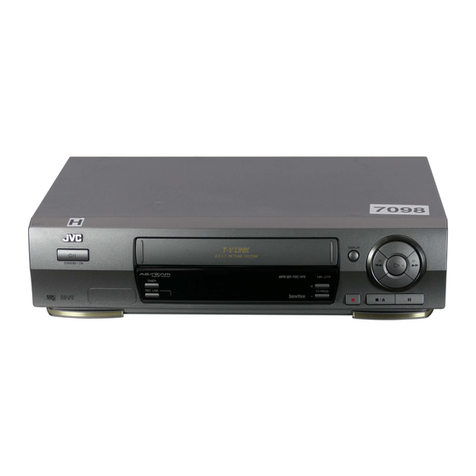
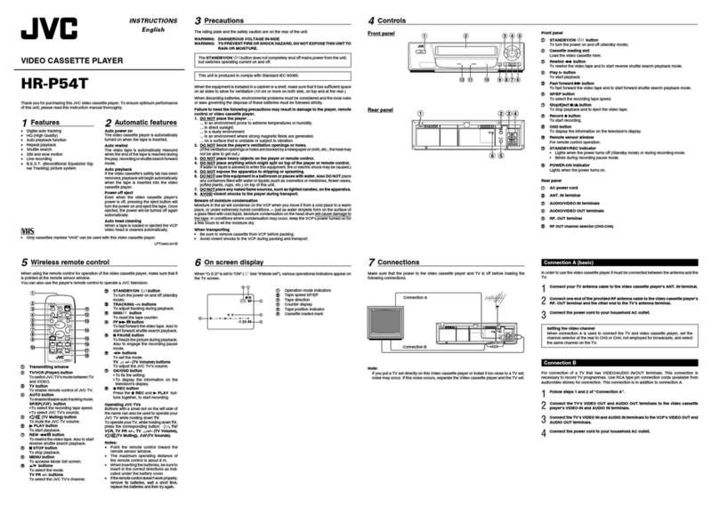
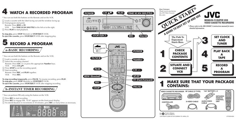
JVC HR-S2901U User manual

SERVICE MANUAL
No.82912
March 2002
HR-S2901U, HR-S2911U(C),
HR-S3901U,
HR-S3911U, HR-S3911U(C)
Regarding service information other than these sections, refer to the HR-S5901U service manual (No.82911).
Also, be sure to note important safety precautions provided in the service manual.
VIDEO CASSETTE RECORDER
This service manual is printed on 100% recycled paper.
COPYRIGHT © 2002 VICTOR COMPANY OF JAPAN, LTD
SPECIFICATIONS
(The specifications shown pertain specifically to the model HR-S3901U.)
V15S0/S1
REW FF
REC LINK
24HR QUICK
PROGRAM
POWER DISPLAY SP/EP
Specifications shown are for SP mode unless specified otherwise.
E. & O.E. Design and specifications subject to change without
notice.
GENERAL
Power requirement : AC 120 V
d
, 60 Hz
Power consumption
Power on : 17 W
Power off : 1.5 W
Temperature
Operating : 5°C to 40°C (41°F to 104°F)
Storage : –20°C to 60°C (–4°F to140°F)
Operating position : Horizontal only
Dimensions (W x H x D) : 435 mm x 94 mm x 247 mm
(17-3/16" x 3-3/4" x 9-3/4")
Weight : 2.8 kg (6.2 lbs)
Format : S-VHS/VHS NTSC standard
Maximum recording time
SP : 210 min. with ST-210 video cassette
EP : 630 min. with ST-210 video cassette
VIDEO/AUDIO
Signal system : NTSC-type color signal and EIA
monochrome signal, 525 lines/
60 fields
Recording/Playback
system
: DA-4 (Double Azimuth) head helical
scan system
Signal-to-noise ratio : 45 dB
Horizontal resolution
VHS : 230 lines
S-VHS : 400 lines
Frequency range
Normal audio : 70 Hz to 10,000 Hz
Hi-Fi audio : 20 Hz to 20,000 Hz
Input/Output : RCA connectors (IN x 2, OUT x 1)
S-video connectors (IN x 1, OUT x 1)
TUNER
Tuning system : Frequency-synthesized tuner
Channel coverage
VHF : Channels 2–13
UHF : Channels 14–69
CATV : 113 Channels
RF output : Channel 3 or 4 (switchable; preset to
Channel 3 when shipped) 75 ohms,
unbalanced
TIMER
Clock reference : Quartz
Program capacity : 1-year programable timer/8 programs
Memory backup for timer is not supported.
ACCESSORIES
Provided accessories : Infrared remote control unit,
“AA” battery x 2,
S-video cable (4-pin),
RF cable (F-type)

TABLE OF CONTENTS
The following table indicate main different points between models HR-S5901U, HR-S2901U, HR-S2911U(C), HR-S3901U, HR-S3911U
and HR-S3911U(C).
MODEL HR-S5901U
ITEM
BODY COLOR BLACK PURE SILVER BLACK PURE SILVER
ADVANCED JOG USED NOT USED USED
MULTI BRAND REMOCON USED NOT USED USED
ILLUMI FUNCTION USED NOT USED
FLYING ERASE HEAD USED NOT USED
INSERT USED/BUTTON NOT USED
AUDIO DUBBING USED/BUTTON NOT USED
FRONT S IN USED NOT USED
REAR S,A/V IN USED NOT USED USED
VCR PLUS+ USED NOT USED USED
REC LINK USED NOT USED USED
CABLE BOX /DBS.BOX CONTROL
USED NOT USED USED
HR-S2901U
1
DIFFERENT TABLE ............................................................................................................................................................................................... 1 to 2
5. PARTS LIST (5-1 to 5-7)
5.1 PACKING AVD ACCESSORY PARTS LIST<M1>.................................................................................................................................. 5-1
5.2 ELECTRICAL PARTS LIST .................................................................................................................................................................... 5-2
MAIN BOARD ASSEMBLY <03> ........................................................................................................................................................... 5-2
HR-S2911U(C) HR-S3901U HR-S3911U HR-S3911U(C)
Note: Mark is same as left.

2
MAIN BOARD ASSEMBLY<03>
REF
NO.
!MODEL HR-S5901U
ITEM
PW1 MAIN BOARD ASSY LPA10155-02C1 LPA10155-03B1 LPA10155-04B1
HR-S2901U HR-S2911U(C) HR-S3901U HR-S3911U HR-S3911U(C)
Note: Mark is same as left.
Mark — is not used.
REAR S JACK BOARD ASSEMBLY<29>
REF
NO.
!MODEL HR-S5901U
ITEM
PW5
REAR S JACK BOARD ASSY
LPA10155-01A5 LPA10155-02A5 LPA10155-01A5
R928 MG RESISTOR NRSA02J-750X — — NRSA02J-750X
R929 MG RESISTOR NRSA02J-750X — — NRSA02J-750X
C915 MG RESISTOR NRSA02J-0R0X — — NRSA02J-0R0X
J4 S JACK QND0077-001 QND0076-001 QND0077-001
HR-S2901U HR-S2911U(C) HR-S3901U HR-S3911U HR-S3911U(C)
FRONT S JACK BOARD ASSEMBLY<36>
REF
NO.
!MODEL HR-S5901U
ITEM
PW4
FRONT S JACK BOARD ASSY
LPA10155-01A4 — — — — —
J7102
S JACK QND0084-001 — — — — —
CN7108
FPC CONNECTOR QGF1209F1-04 — — — — —
HR-S2901U HR-S2911U(C) HR-S3901U HR-S3911U HR-S3911U(C)
ADV. JOG/SW BOARD ASSEMBLY<38>
REF
NO.
!MODEL HR-S5901U
ITEM
PW6
ADV. JOG/SW BOARD ASSY
LPA10155-01A6 — — LPA10155-01A6
R7047
MG RESISTOR NRSA02J-682X — — NRSA02J-682X
R7048
MG RESISTOR NRSA02J-472X — — NRSA02J-472X
S7030
TACT SWITCH QSW0456-002Z — — QSW0456-002Z
S7031
TACT SWITCH QSW0456-002Z — — QSW0456-002Z
UN7001
ROTARY ENCODER QSW0905-001 — — QSW0905-001
CN7003
FPC CONNECTOR QGF1209-F1-04 — — QGF1209-F1-04
HR-S2901U HR-S2911U(C) HR-S3901U HR-S3911U HR-S3911U(C)
R. PAUSE BOARD ASSEMBLY<99>
REF
NO.
!MODEL HR-S5901U
ITEM
PW2 R. PAUSE BOARD ASSY LPA10155-02A2 — — LPA10155-02A2
R7155
MG RESISTOR NRSA02J-101X — — NRSA02J-101X
R7156
MG RESISTOR NRSA02J-101X — — NRSA02J-101X
J7104
MINI JACK PU60612 — — PU60612
J7105
MINIJACK PU60612 — — PU60612
HR-S2901U HR-S2911U(C) HR-S3901U HR-S3911U HR-S3911U(C)
FINAL ASSEMBLY<M2>
REF
NO.
!MODEL HR-S5901U
ITEM
!501 FRONT PANELASSY LP10415-007B LP10415-003B LP10415-004B LP10415-005B LP10415-006B
501A CASSETTE DOOR LP21080-004A LP21080-002A LP21080-003A LP21080-002A LP21080-003A
501C DISPLAY WINDOW LP21081-003A LP21081-001A LP21081-002A
501D COVER(R) LP31056-006A LP31056-002A LP31056-003A LP31056-004A LP31056-005A
501E COVER(L) LP31057-007A LP31057-003A LP31057-004A LP31057-005A LP31057-006A
!502 TOP COVER LP10418-001C LP10418-002C LP10418-001C LP10418-002C
503 SCREW,X3,TOPCOVER QYTDSF3010M QYTDSF3010R QYTDSF3010M QYTDSF3010R
505 DRUM ASSY PDV2545A PDV2542A
529 KNOB ASSY LP31095-003A — — LP31095-002A LP31095-001A
530
SCREW,X3,ADV.JOG/SW
QYTDSF2608Z — — QYTDSF2608Z
531
SCREW,X2,FRONT S JACK
QYTDSF2608Z — — — — —
HR-S2901U HR-S2911U(C) HR-S3901U HR-S3911U HR-S3911U(C)
The following tables indicate different parts number between models HR-S5901U, HR-S2901U, HR-S2911U(C), HR-S3901U,
HR-S3911U and HR-S3911U(C).
PACKING AND ACCESSORY ASSEMBLY<M1>
PACKING AND ACCESSORYASSEMBLY<M1> is indicated on the parts list.


JVC SERVICE & ENGINEERING COMPANY OF AMERICA
DIVISION OF JVC AMERICAS CORP.
Head office
East Coast
Midwest
West Coast
Atlanta
Hawaii
:
:
:
:
:
:
1700 Valley Road Wayne, New Jersey 07470-9976
10 New Maple Avenue Pine Brook, New Jersey 07058-9641
705 Enterprise Street Aurora, Illinois 60504-8149
5665 Corporate Avenue Cypress, California 90630-0024
1500 Lakes Parkway Lawrenceville, Georgia 30043-5857
2969 Mapunapuna Place Honolulu, Hawaii 96819-2040
(973)317-5000
(973)396-1000
(630)851-7855
(714)229-8011
(770)339-2582
(808)833-5828
JVC CANADA INC.
Head office
Montreal
Vancouver
:
:
:
21 Finchdene Square Scarborough, Ontario M1X 1A7
16800 Rte Trans-Canadienne, Kirkland, Quebec H9H 5G7
13040 Worster Court Richmond, B.C. V6V 2B3
(416)293-1311
(514)871-1311
(604)270-1311
Printed in Japan
S40895-04

5-1
SECTION 5
PARTS LIST
SAFETY PRECAUTION
Parts identified by the !symbol are critical for safety. Replace only with specified part numbers.
5.1 PACKING AND ACCESSORY ASSEMBLY <M1>
The instruction manual to be provided with this product will differ according to the destination.
******************************
PACKING AND ACCESSORY ASSEMBLY <M1>
301 LP31089-013A PACKING CASE,A
LP31089-016A PACKING CASE,B
LP31089-019A PACKING CASE,C
LP31089-022A PACKING CASE,D,E
302 LP31091-001B CUSHION ASSY
303 PQM30021-95 POLY BAG
306 LP20878-001A REMOTE CONTROLLER,A,B
LP20878-009A REMOTE CONTROLLER,C,D,E
306A LP40610-001A COVER(BATTERY)
--------------- ----------------------- ----------------------------------------------------- ---------------- ----------------------- ------------------------------------------------------
#REF No. PART No. PART NAME, DESCRIPTION # REF No. PART No. PART NAME, DESCRIPTION
307 – BATTERY,X2(“AA”TYPE)
308 QPC02202230P POLY BAG
!
310 LPT0636-001A INST.BOOK(EN),A,B
!
LPT0636-002A INST.BOOK(FR),B
!
LPT0637-001A INST.BOOK(EN),C,D,E
!
LPT0637-002A INST.BOOK(FR),E
311 QPC02503530P POLY BAG
312 PEAC0294-04 RF CABLE
314 QAM0004-002 S CABLE,C,D,E
316 BT-52004-2 WARRANTY CARD,B,E
317 BT-51028-1 REGIST.CARD,A,C,D
319 BT-20071B SER.NET CARD,B,E
320 LP30666-004A SHEET(COUPON),C,D,E
320
301
302
302
FINAL ASSY <M2>
306
306A
311
303
ADHESIVE
TAPE
317
316
310
319
ADHESIVE
TAPE
307
312
308
SPEC OF BARCODE
314
MODEL MARK
HR-S2901U A
HR-S2911U(C) B
HR-S3901U C
HR-S3911U D
HR-S3911U(C) E

--------------- ----------------------- ----------------------------------------------------- ---------------- ----------------------- ------------------------------------------------------
# REF No. PART No. PART NAME, DESCRIPTION # REF No. PART No. PART NAME, DESCRIPTION
5-2
5.2 ELECTRICAL PARTS LIST
******************************
MAIN BOARD ASSEMBLY <03>
PW1 MAIN BOARD ASS'Y<03> includes the parts shown in the following.
PW1 2D DIGITAL BOARD ASS'Y<05>
PW1 LPA10155-03B1 MAIN BOARD ASSY,A,B
LPA10155-04B1 MAIN BOARD ASSY,C,D,E
IC1 JCP8051-NSA IC
or JCP8051-MSA IC
IC501 JCP8038 IC
IC502 VC2076DP IC
!
IC2201 AN3663FBP IC
IC3001 MN101D06HJE IC,C,D,E
MN101D06GJG IC,A,B
or MN101DF06KAFJE IC,C,D,E
or MN101DF06KAFJG IC,A,B
IC3004 LPN0734-003A-03 IC(EEPROM),A,B
LPN0735-003A-01 IC(EEPROM),C,D,E
IC7002 GP1U291Q IR DETECT UNIT
or PIC-37143LJ IR DETECT UNIT
or PNA4652M00YC IR DETECT UNIT
Q7 2SC4081/QRS/-X TRANSISTOR
or 2PC4081/R/-X TRANSISTOR
Q8 2SC4081/QRS/-X TRANSISTOR
or 2PC4081/R/-X TRANSISTOR
Q9 2SA1576A/QR/-X TRANSISTOR
or 2PA1576/R/-X TRANSISTOR
Q12 2SA1576A/QR/-X TRANSISTOR
or 2PA1576/R/-X TRANSISTOR
Q17 DTC144WU DIGI TRANSISTOR
or PDTC144WU DIGI TRANSISTOR
or RN1309 DIGI TRANSISTOR
or UN521E DIGI TRANSISTOR
Q21 2SA1576A/QR/-X TRANSISTOR
or 2PA1576/R/-X TRANSISTOR
Q33 DTC144WU DIGI TRANSISTOR
or PDTC144WU DIGI TRANSISTOR
or UN521E DIGI TRANSISTOR
or RN1309 DIGI TRANSISTOR
Q38 2SC4081/QRS/-X TRANSISTOR
or 2PC4081/R/-X TRANSISTOR
Q901 2SA1576A/QR/-X TRANSISTOR
or 2PA1576/R/-X TRANSISTOR
Q903 2SA1576A/QR/-X TRANSISTOR
or 2PA1576/R/-X TRANSISTOR
Q904 2SA1576A/QR/-X TRANSISTOR
or 2PA1576/R/-X TRANSISTOR
Q2001 2SC4081/QRS/-X TRANSISTOR
or 2PC4081/R/-X TRANSISTOR
or 2SD1819A/QRS/-X TRANSISTOR
Q2002 2SC4081/QRS/-X TRANSISTOR
or 2PC4081/R/-X TRANSISTOR
or 2SD1819A/QRS/-X TRANSISTOR
Q2003 DTA144WU DIGI TRANSISTOR
or PDTA144WU DIGI TRANSISTOR
or RN2309 TRANSISTOR
or UN511E DIGI TRANSISTOR
Q2051 2SC4081/QRS/-X TRANSISTOR
or 2SD1819A/QRS/-X TRANSISTOR
or 2PC4081/R/-X TRANSISTOR
Q2052 2SA1576A/QR/-X TRANSISTOR
or 2PA1576/R/-X TRANSISTOR
or 2SB1218A/QR/-X TRANSISTOR
Q2053 DTC144WU DIGI TRANSISTOR
or PDTC144WU DIGI TRANSISTOR
or RN1309 DIGI TRANSISTOR
or UN521E DIGI TRANSISTOR
Q2054 2SA1576A/QR/-X TRANSISTOR
or 2SB1218A/QR/-X TRANSISTOR
or 2PA1576/R/-X TRANSISTOR
Q2055 DTC144WU DIGI TRANSISTOR
or PDTC144WU DIGI TRANSISTOR
or RN1309 DIGI TRANSISTOR
or UN521E DIGI TRANSISTOR
Q2201 DTA144WU DIGI TRANSISTOR
or PDTA144WU DIGI TRANSISTOR
or RN2309 TRANSISTOR
or UN511E DIGI TRANSISTOR
Q2202 DTC144WU DIGI TRANSISTOR
or PDTC144WU DIGI TRANSISTOR
or RN1309 DIGI TRANSISTOR
or UN521E DIGI TRANSISTOR
Q2203 2SC4081/QRS/-X TRANSISTOR
or 2SD1819A/QRS/-X TRANSISTOR
or 2PC4081/R/-X TRANSISTOR
Q2204 2SC4081/QRS/-X TRANSISTOR
or 2PC4081/R/-X TRANSISTOR
or 2SD1819A/QRS/-X TRANSISTOR
Q2251 DTC144WU DIGI TRANSISTOR
or PDTC144WU DIGI TRANSISTOR
or RN1309 DIGI TRANSISTOR
or UN521E DIGI TRANSISTOR
Q2252 DTC144WU DIGI TRANSISTOR
or PDTC144WU DIGI TRANSISTOR
or RN1309 DIGI TRANSISTOR
or UN521E DIGI TRANSISTOR
Q2253 DTC144WU DIGI TRANSISTOR
or PDTC144WU DIGI TRANSISTOR
or RN1309 DIGI TRANSISTOR
or UN521E DIGI TRANSISTOR
Q2254 DTC114EU DIGI TRANSISTOR
or PDTC114EU DIGI TRANSISTOR
or RN1302 DIGI TRANSISTOR
or UN5211 DIGI TRANSISTOR
Q3002 PTZ-NV16A PHOTO TRANSISTOR
Q3005 UN521K TRANSISTOR,C,D,E
or DTC114WU DIGI TRANSISTOR,C,D,E
Q3006 2SC4081/QRS/-X TRANSISTOR
Q3007 2SC4081/QRS/-X TRANSISTOR
Q4001 UN5211 DIGI TRANSISTOR
or PDTC114EU DIGI TRANSISTOR
or DTC114EU DIGI TRANSISTOR
or RN1302 DIGI TRANSISTOR
Q4002 2SD1819A/QRS/-X TRANSISTOR
or 2SC4081/QRS/-X TRANSISTOR
or 2PC4081/R/-X TRANSISTOR
Q5101 2SK2043-CB14 FE TRANSISTOR
or 2SK2043 FE TRANSISTOR
Q5102 2SD2144S/UV/-T TRANSISTOR
Q5301 2SC1740S/RS/-T TRANSISTOR
or 2SC3199/YG/-T TRANSISTOR
Q5303 2SC5739/QP/ TRANSISTOR
MODEL MODELMARK MARK
HR-S2901U
A
HR-S2911U(C)
B
HR-S3901U
C
HR-S3911U
D
HR-S3911U(C)
E

5-3
--------------- ----------------------- ----------------------------------------------------- ---------------- ----------------------- ------------------------------------------------------
# REF No. PARTNo. PART NAME, DESCRIPTION # REF No. PART No. PART NAME, DESCRIPTION
Q5304 2SD2144S/UV/-T TRANSISTOR
Q5305 DTA114EU DIGI TRANSISTOR
or PDTA114EU DIGI TRANSISTOR
or RN2302 TRANSISTOR
or UN5111 DIGI TRANSISTOR
Q5306 DTC114EU DIGI TRANSISTOR
or PDTC114EU DIGI TRANSISTOR
or UN5211 DIGI TRANSISTOR
or RN1302 DIGI TRANSISTOR
Q6030 2SB1218A/QR/-X TRANSISTOR
or 2SA1576A/QR/-X TRANSISTOR
or 2PA1576/R/-X TRANSISTOR
Q7001 DTA143TU DIGI TRANSISTOR
Q7002 DTA143TU DIGI TRANSISTOR
Q7003 DTA143TU DIGI TRANSISTOR
Q7004 DTA143TU DIGI TRANSISTOR
Q7005 DTA143TU DIGI TRANSISTOR
Q7008 DTC143TU DIGI TRANSISTOR
Q7009 DTC143TU DIGI TRANSISTOR
Q7010 DTC143TU DIGI TRANSISTOR
Q7011 DTC143TU DIGI TRANSISTOR
Q7012 DTC143TU DIGI TRANSISTOR
Q7013 DTC143TU DIGI TRANSISTOR
Q7014 DTC143TU DIGI TRANSISTOR
Q7201 2SA720/RS/-T
TRANSISTOR,C,D,E
D1 QUY153-050Y IM BUS WIRE
D502 1SS133 DIODE,C,D,E
or 1SS270A DIODE,C,D,E
D503 1SS133 DIODE,C,D,E
or 1SS270A DIODE,C,D,E
D2251 1SS133 DIODE
or 1SS270A DIODE
D3001 LNB2301L01VI LE DIODE
D3002 1SS133 DIODE
or 1SS270A DIODE
D3005 11ES2 DIODE
or 1A3G DIODE
D3007 1SS133 DIODE,C,D,E
or 1SS270A DIODE,C,D,E
D3016 MTZJ3.9B ZENER DIODE
or RD3.9ES/B2/-T2 ZENER DIODE
D5001 S1WB/A/60-4102 BRIDGE DIODE
or S1WB/A/60-X BRIDGE DIODE
or S1WB(A)60F4072X BRIDGE DIODE
D5101 AU01 DIODE
or 10ELS4 FR DIODE
D5102 AU01 DIODE
or 10ELS4 FR DIODE
D5103 1SS133 DIODE
or 1SS270A DIODE
D5105 1SS133 DIODE
or 1SS270A DIODE
D5203 AU01Z FR DIODE
or 10ELS2 FR DIODE
D5204 AU01Z FR DIODE
or 10ELS2 FR DIODE
D5206 AW04 SB DIODE
or SBO40 SB DIODE
or 1S4 SB DIODE
or AK04 SB DIODE
or 11EQS04 SB DIODE
D5207 AW04 SB DIODE
or SBO40 SB DIODE
or AK04 SB DIODE
or 1S4 SB DIODE
or 11EQS04 SB DIODE
D5210 AU01Z FR DIODE
or PG104RS FR DIODE
or 10ELS2 FR DIODE
or ERA18-02-T2 FR DIODE
or 1SR153-400-T2 FR DIODE
D5301 MTZJ15C ZENER DIODE
or RD15ES/B3/-T2 ZENER DIODE
D5302 MTZJ12A ZENER DIODE
or RD12ES/B1/-T2 ZENER DIODE
D5303 MTZJ5.6A ZENER DIODE
or RD5.6ES/B1/-T2 ZENER DIODE
D5304 QUY153-050Y IM BUS WIRE
D5305 MTZJ5.6C ZENER DIODE
or RD5.6ES/B3/-T2 ZENER DIODE
D6002 HZ30-2L-T2 ZENER DIODE
or HZ30-2LTD Z DIODE (M)
R1 NRSA02J-622X MG RESISTOR 6.2kØ,1/10W
R2 NRSA02J-152X MG RESISTOR 1.5kØ,1/10W
R3 NRSA02J-471X MG RESISTOR 470Ø,1/10W
R6 NRSA02J-103X MG RESISTOR 10kØ,1/10W
R7 NRSA02J-102X MG RESISTOR 1kØ,1/10W
R8 NRSA02J-471X MG RESISTOR 470Ø,1/10W
R9 NRSA02J-471X MG RESISTOR 470Ø,1/10W
R12 NRSA02J-101X MG RESISTOR 100Ø,1/10W
R25 NRSA02J-103X MG RESISTOR 10kØ,1/10W
R26 NRSA02J-822X MG RESISTOR 8.2kØ,1/10W
R27 NRSA02J-102X MG RESISTOR 1kØ,1/10W
R28 NRSA02J-102X MG RESISTOR 1kØ,1/10W
R29 NRSA02J-222X MG RESISTOR 2.2kØ,1/10W
R31 NRSA02J-122X MG RESISTOR 1.2kØ,1/10W
R32 NRSA02J-102X MG RESISTOR 1kØ,1/10W
R34 NRSA02J-223X MG RESISTOR 22kØ,1/10W
R36 NRSA02J-182X MG RESISTOR 1.8kØ,1/10W
R42 NRSA02J-681X MG RESISTOR 680Ø,1/10W
R44 NRSA02J-223X MG RESISTOR 22kØ,1/10W
R45 NRSA02J-333X MG RESISTOR 33kØ,1/10W
R46 NRSA02J-221X MG RESISTOR 220Ø,1/10W
R48 NRSA02J-102X MG RESISTOR 1kØ,1/10W
R68 NRSA02J-222X MG RESISTOR 2.2kØ,1/10W
R77 NRSA02J-103X MG RESISTOR 10kØ,1/10W
R90 NRSA02J-471X MG RESISTOR 470Ø,1/10W
R93 NRSA02J-102X MG RESISTOR 1kØ,1/10W
R104 NRSA02J-682X MG RESISTOR 6.8kØ,1/10W
R118 NRSA02J-0R0X MG RESISTOR 0Ø,1/10W
R120 NRSA02J-0R0X MG RESISTOR 0Ø,1/10W
R201 NRSA02J-332X MG RESISTOR 3.3kØ,1/10W
R202 NRSA02J-222X MG RESISTOR 2.2kØ,1/10W
R503 NRSA02J-221X MG RESISTOR 220Ø,1/10W
R504 NRSA02J-332X MG RESISTOR 3.3kØ,1/10W
R505 NRSA02J-392X MG RESISTOR 3.9kØ,1/10W
R506 NRSA02J-391X MG RESISTOR 390Ø,1/10W
R507 NRSA02J-122X MG RESISTOR 1.2kØ,1/10W
R508 NRSA02J-151X MG RESISTOR 150Ø,1/10W
R509 NRSA02J-162X MG RESISTOR 1.6kØ,1/10W
R510 NRVA02D-102X CMF RESISTOR 1kØ,1/10W
R511 NRVA02D-471X CMF RESISTOR 470Ø,1/10W

--------------- ----------------------- ----------------------------------------------------- ---------------- ----------------------- ------------------------------------------------------
# REF No. PART No. PART NAME, DESCRIPTION # REF No. PART No. PART NAME, DESCRIPTION
5-4
R512 NRVA02D-102X CMF RESISTOR 1kØ,1/10W
R513 NRVA02D-152X CMF RESISTOR 1.5kØ,1/10W
R514 NRVA02D-332X CMF RESISTOR 3.3kØ,1/10W
R515 NRVA02D-332X CMF RESISTOR 3.3kØ,1/10W
R901 NRSA02J-820X MG RESISTOR 82Ø,1/10W
R902 NRSA02J-152X MG RESISTOR 1.5kØ,1/10W
R904 QRE123J-331X RESISTOR 330Ø,1/2W
R905 NRSA02J-101X MG RESISTOR 100Ø,1/10W
R911 NRSA02J-750X MG RESISTOR,C,D,E 75Ø,1/10W
R912 NRSA02J-750X MG RESISTOR 75Ø,1/10W
R916 NRSA02J-750X MG RESISTOR 75Ø,1/10W
R917 NRSA02J-750X MG RESISTOR 75Ø,1/10W
R919 QRE123J-331X RESISTOR 330Ø,1/2W
R920 NRSA02J-101X MG RESISTOR 100Ø,1/10W
R921 NRSA02J-101X MG RESISTOR 100Ø,1/10W
R922 QRE123J-331X RESISTOR 330Ø,1/2W
R929 NRSA02J-750X MG RESISTOR 75Ø,1/10W
R2003 NRSA02J-101X MG RESISTOR 100Ø,1/10W
R2007 NRSA02J-123X MG RESISTOR 12kØ,1/10W
R2010 NRSA02J-123X MG RESISTOR 12kØ,1/10W
R2013 NRSA02J-682X MG RESISTOR 6.8kØ,1/10W
R2014 NRSA02J-224X MG RESISTOR 220kØ,1/10W
R2015 NRSA02J-221X MG RESISTOR 220Ø,1/10W
R2016 NRSA02J-473X MG RESISTOR 47kØ,1/10W
R2017 NRSA02J-153X MG RESISTOR 15kØ,1/10W
R2018 NRSA02J-472X MG RESISTOR 4.7kØ,1/10W
R2019 NRSA02J-472X MG RESISTOR 4.7kØ,1/10W
R2053 NRSA02J-562X MG RESISTOR 5.6kØ,1/10W
R2054 NRSA02J-123X MG RESISTOR 12kØ,1/10W
R2055 NRSA02J-3R3X MG RESISTOR 3.3Ø,1/10W
R2056 QRE141J-820Y RESISTOR 82Ø,1/4W
R2057 NRSA02J-473X MG RESISTOR 47kØ,1/10W
R2058 NRSA02J-183X MG RESISTOR 18kØ,1/10W
R2059 NRSA02J-473X MG RESISTOR 47kØ,1/10W
R2060 NRSA02J-183X MG RESISTOR 18kØ,1/10W
R2201 NRSA02J-473X MG RESISTOR 47kØ,1/10W
R2202 NRSA02J-682X MG RESISTOR 6.8kØ,1/10W
R2203 NRSA02J-473X MG RESISTOR,C,D,E 47kØ,1/10W
R2204 NRSA02J-682X MG RESISTOR,C,D,E 6.8kØ,1/10W
R2205 NRSA02J-473X MG RESISTOR 47kØ,1/10W
R2206 NRSA02J-682X MG RESISTOR 6.8kØ,1/10W
R2207 NRSA02J-473X MG RESISTOR,C,D,E 47kØ,1/10W
R2208 NRSA02J-682X MG RESISTOR,C,D,E 6.8kØ,1/10W
R2209 NRSA02J-101X MG RESISTOR 100Ø,1/10W
R2210 NRSA02J-472X MG RESISTOR 4.7kØ,1/10W
R2211 NRSA02J-332X MG RESISTOR 3.3kØ,1/10W
R2212 NRSA02J-332X MG RESISTOR 3.3kØ,1/10W
R2213 NRSA02J-472X MG RESISTOR 4.7kØ,1/10W
R2214 NRSA02J-101X MG RESISTOR 100Ø,1/10W
R2215 QRE141J-221Y RESISTOR 220Ø,1/4W
R2216 NRSA02J-102X MG RESISTOR 1kØ,1/10W
R2217 NRSA02J-472X MG RESISTOR 4.7kØ,1/10W
R2218 NRSA02J-392X MG RESISTOR 3.9kØ,1/10W
R2219 NRSA02J-102X MG RESISTOR 1kØ,1/10W
R2220 NRSA02J-102X MG RESISTOR 1kØ,1/10W
R2230 NRSA02J-471X MG RESISTOR 470Ø,1/10W
R2231 NRSA02J-471X MG RESISTOR 470Ø,1/10W
R2251 NRSA02J-472X MG RESISTOR 4.7kØ,1/10W
R2252 NRSA02J-332X MG RESISTOR 3.3kØ,1/10W
R2253 NRSA02J-101X MG RESISTOR 100Ø,1/10W
R2254 NRSA02J-103X MG RESISTOR 10kØ,1/10W
R2255 NRSA02J-273X MG RESISTOR 27kØ,1/10W
R2256 NRSA02J-222X MG RESISTOR 2.2kØ,1/10W
R2257 NRSA02J-684X MG RESISTOR 680kØ,1/10W
R2258 NRSA02J-0R0X MG RESISTOR 0Ø,1/10W
R3003 NRSA02J-102X MG RESISTOR,C,D,E 1kØ,1/10W
R3004 QUY160-100Y IM BUS WIRE
R3005 QRE141J-102Y RESISTOR 1kØ,1/4W
R3006 QUY160-100Y IM BUS WIRE
R3007 QUY160-100Y IM BUS WIRE
R3008 QUY160-100Y IM BUS WIRE
R3009 QUY160-100Y IM BUS WIRE
R3010 QUY160-100Y IM BUS WIRE
R3011 QUY160-100Y IM BUS WIRE
R3012 QUY160-100Y IM BUS WIRE
R3016 NRSA02J-102X MG RESISTOR 1kØ,1/10W
R3017 NRSA02J-471X MG RESISTOR 470Ø,1/10W
R3018 NRSA02J-471X MG RESISTOR 470Ø,1/10W
R3021 NRSA02J-102X MG RESISTOR 1kØ,1/10W
R3022 NRSA02J-102X MG RESISTOR 1kØ,1/10W
R3031 NRSA02J-471X MG RESISTOR 470Ø,1/10W
R3032 NRSA02J-471X MG RESISTOR 470Ø,1/10W
R3035 NRSA02J-102X MG RESISTOR 1kØ,1/10W
R3055 NRSA02J-102X MG RESISTOR 1kØ,1/10W
R3058 NRSA02J-102X MG RESISTOR 1kØ,1/10W
R3060 NRSA02J-102X MG RESISTOR 1kØ,1/10W
R3064 NRSA02J-102X MG RESISTOR 1kØ,1/10W
R3066 NRSA02J-102X MG RESISTOR 1kØ,1/10W
R3084 NRSA02J-102X MG RESISTOR 1kØ,1/10W
R3086 NRSA02J-102X MG RESISTOR,C,D,E 1kØ,1/10W
R3087 NRSA02J-102X MG RESISTOR,C,D,E 1kØ,1/10W
R3090 NRSA02J-102X MG RESISTOR 1kØ,1/10W
R3091 NRSA02J-472X MG RESISTOR 4.7kØ,1/10W
R3092 NRSA02J-472X MG RESISTOR 4.7kØ,1/10W
R3093 NRSA02J-472X MG RESISTOR 4.7kØ,1/10W
R3094 NRSA02J-472X MG RESISTOR 4.7kØ,1/10W
R3095 QUY160-100Y IM BUS WIRE
R3096 QUY160-100Y IM BUS WIRE
R3097 QUY160-100Y IM BUS WIRE
R3098 QUY160-100Y IM BUS WIRE
R3099 QUY160-100Y IM BUS WIRE
R3100 QUY160-100Y IM BUS WIRE
R3205 NRSA02J-103X MG RESISTOR 10kØ,1/10W
R3206 NRSA02J-103X MG RESISTOR 10kØ,1/10W
R3207 NRSA02J-103X MG RESISTOR 10kØ,1/10W
R3208 NRSA02J-103X MG RESISTOR 10kØ,1/10W
R3209 QRE141J-181Y RESISTOR 180Ø,1/4W
R3211 QRE141J-183Y RESISTOR 18kØ,1/4W
R3212 NRSA02J-121X MG RESISTOR 120Ø,1/10W
R3213 NRSA02J-183X MG RESISTOR 18kØ,1/10W
R3214 NRSA02J-121X MG RESISTOR 120Ø,1/10W
R3215 NRSA02J-183X MG RESISTOR 18kØ,1/10W
R3216 NRSA02J-474X MG RESISTOR 470kØ,1/10W
R3217 NRSA02J-334X MG RESISTOR 330kØ,1/10W
R3218 NRSA02J-103X MG RESISTOR 10kØ,1/10W
R3219 NRSA02J-103X MG RESISTOR 10kØ,1/10W
R3220 NRSA02J-562X MG RESISTOR 5.6kØ,1/10W
R3222 NRSA02J-471X MG RESISTOR 470Ø,1/10W
R3223 NRSA02J-105X MG RESISTOR 1MØ,1/10W
R3224 NRSA02J-101X MG RESISTOR 100Ø,1/10W
R3226 NRSA02J-472X MG RESISTOR 4.7kØ,1/10W
R3227 NRSA02J-472X MG RESISTOR 4.7kØ,1/10W

5-5
--------------- ----------------------- ----------------------------------------------------- ---------------- ----------------------- ------------------------------------------------------
# REF No. PARTNo. PART NAME, DESCRIPTION # REF No. PART No. PART NAME, DESCRIPTION
R3236 NRSA02J-103X MG RESISTOR 10kØ,1/10W
R3237 NRSA02J-103X MG RESISTOR 10kØ,1/10W
R3238 NRSA02J-103X MG RESISTOR 10kØ,1/10W
R3240 NRSA02J-103X MG RESISTOR 10kØ,1/10W
R3241 NRSA02J-103X MG RESISTOR 10kØ,1/10W
R3242 NRSA02J-103X MG RESISTOR 10kØ,1/10W
R3243 NRSA02J-681X MG RESISTOR 680Ø,1/10W
R3244 NRSA02J-331X MG RESISTOR 330Ø,1/10W
R3245 NRSA02J-682X MG RESISTOR 6.8kØ,1/10W
R3252 QRE141J-153Y RESISTOR 15kØ,1/4W
R3253 NRSA02J-103X MG RESISTOR 10kØ,1/10W
R4001 NRSA02J-222X MG RESISTOR 2.2kØ,1/10W
R4002 NRSA02J-562X MG RESISTOR 5.6kØ,1/10W
R4003 NRSA02J-0R0X MG RESISTOR 0Ø,1/10W
R4006 NRSA02J-472X MG RESISTOR 4.7kØ,1/10W
R4010 NRSA02J-471X MG RESISTOR 470Ø,1/10W
R4011 NRSA02J-471X MG RESISTOR 470Ø,1/10W
R4012 NRSA02J-153X MG RESISTOR 15kØ,1/10W
R4018 NRSA02J-102X MG RESISTOR 1kØ,1/10W
R4019 NRSA02J-102X MG RESISTOR 1kØ,1/10W
!
R5001 QRZ9046-475Z RESISTOR 4.7MØ,1/2W
R5101 QRE141J-334Y RESISTOR 330kØ,1/4W
R5102 QRE141J-334Y RESISTOR 330kØ,1/4W
R5103 QRE141J-683Y RESISTOR 68kØ,1/4W
R5104 QRG029J-154G OMF RESISTOR 150kØ,2W
R5106 QRT01DJ-R39X MF RESISTOR 0.39Ø,1W
R5107 QRE121J-331Y RESISTOR 330Ø,1/2W
R5108 NRSA02J-122X MG RESISTOR 1.2kØ,1/10W
R5109 QRE141J-681Y RESISTOR 680Ø,1/4W
R5110 NRSA02J-224X MG RESISTOR 220kØ,1/10W
R5112 NRSA02J-221X MG RESISTOR 220Ø,1/10W
R5302 NRSA02J-102X MG RESISTOR 1kØ,1/10W
R5303 NRSA02J-122X MG RESISTOR 1.2kØ,1/10W
R5304 NRSA02J-471X MG RESISTOR 470Ø,1/10W
R5306 QRE141J-181Y RESISTOR 180Ø,1/4W
R5310 NRSA02J-103X MG RESISTOR 10kØ,1/10W
R5312 NRSA02J-102X MG RESISTOR 1kØ,1/10W
R5313 NRSA02J-102X MG RESISTOR 1kØ,1/10W
R6020 NRSA02J-102X MG RESISTOR 1kØ,1/10W
R6021 NRSA02J-102X MG RESISTOR 1kØ,1/10W
R6030 NRSA02J-332X MG RESISTOR 3.3kØ,1/10W
R6031 NRSA02J-101X MG RESISTOR 100Ø,1/10W
R6050 QRE141J-330Y RESISTOR 33Ø,1/4W
R6051 NRSA02J-102X MG RESISTOR 1kØ,1/10W
R6502 NRSA02J-332X MG RESISTOR 3.3kØ,1/10W
R6503 NRSA02J-153X MG RESISTOR 15kØ,1/10W
R6504 NRSA02J-103X MG RESISTOR 10kØ,1/10W
R7002 NRSA02J-331X MG RESISTOR 330Ø,1/10W
R7003 NRSA02J-331X MG RESISTOR 330Ø,1/10W
R7004 NRSA02J-331X MG RESISTOR 330Ø,1/10W
R7005 NRSA02J-331X MG RESISTOR 330Ø,1/10W
R7006 NRSA02J-331X MG RESISTOR 330Ø,1/10W
R7007 NRSA02J-331X MG RESISTOR 330Ø,1/10W
R7008 NRSA02J-331X MG RESISTOR 330Ø,1/10W
R7015 NRSA02J-0R0X MG RESISTOR 0Ø,1/10W
R7020 NRSA02J-103X MG RESISTOR 10kØ,1/10W
R7021 NRSA02J-122X MG RESISTOR 1.2kØ,1/10W
R7022 NRSA02J-182X MG RESISTOR 1.8kØ,1/10W
R7023 NRSA02J-222X MG RESISTOR 2.2kØ,1/10W
R7024 NRSA02J-272X MG RESISTOR 2.7kØ,1/10W
R7030 NRSA02J-103X MG RESISTOR 10kØ,1/10W
R7031 NRSA02J-122X MG RESISTOR 1.2kØ,1/10W
R7032 NRSA02J-182X MG RESISTOR 1.8kØ,1/10W
R7033 NRSA02J-222X MG RESISTOR 2.2kØ,1/10W
R7034 NRSA02J-272X MG RESISTOR 2.7kØ,1/10W
R7047 NRSA02J-682X MG RESISTOR 6.8kØ,1/10W
R7202 NRSA02J-471X MG RESISTOR,C,D,E 470Ø,1/10W
R7203 NRSA02J-222X MG RESISTOR,C,D,E 2.2kØ,1/10W
R7204 QRE123J-100X RESISTOR,C,D,E 10Ø,1/2W
VR2251 QVP0039-103Z TRIM RESISTOR
B11 NRSA02J-0R0X MG RESISTOR 0Ø,1/10W
B502 NRSA02J-0R0X MG RESISTOR 0Ø,1/10W
B2051 NRSA02J-0R0X MG RESISTOR 0Ø,1/10W
B3001 NRSA02J-0R0X MG RESISTOR 0Ø,1/10W
B5301 NRSA02J-0R0X MG RESISTOR 0Ø,1/10W
B5302 QUY153-050Y IM BUS WIRE
B6020 NRSA02J-0R0X MG RESISTOR 0Ø,1/10W
B7001 NRSA02J-0R0X MG RESISTOR 0Ø,1/10W
C1 NCF21CZ-105X CAPACITOR,C,D,E 1µF,16V
NCF21EZ-104X CAPACITOR,A,B 0.1µF,25V
C2 NCF21CZ-105X CAPACITOR,C,D,E 1µF,16V
NCF21EZ-104X CAPACITOR,A,B 0.1µF,25V
C3 NCF21CZ-105X CAPACITOR,C,D,E 1µF,16V
NCF21EZ-104X CAPACITOR,A,B 0.1µF,25V
C4 NCF21CZ-105X CAPACITOR,C,D,E 1µF,16V
NCF21EZ-104X CAPACITOR,A,B 0.1µF,25V
C5 QEKC0JM-476 E CAPACITOR 47µF,6.3V
C6 QCBB1HK-103 CAPACITOR 0.01µF,50V
C7 NDC21HJ-151X CAPACITOR 150pF,50V
C8 NCB21EK-104X CAPACITOR 0.1µF,25V
C9 NCB21HK-103X CAPACITOR 0.01µF,50V
C10 NDC21HJ-151X CAPACITOR 150pF,50V
C11 NCB21EK-104X CAPACITOR 0.1µF,25V
C12 NDC21HJ-7R0X CAPACITOR 7pF,50V
C14 NCB21EK-104X CAPACITOR 0.1µF,25V
C15 NCB21HK-103X CAPACITOR 0.01µF,50V
C16 NCB21EK-104X CAPACITOR 0.1µF,25V
C17 QEKJ1HM-335 E CAPACITOR 3.3µF,50V
C19 QEKJ1HM-225 E CAPACITOR 2.2µF,50V
C20 QEKJ1HM-105 E CAPACITOR 1µF,50V
C21 NCB21EK-104X CAPACITOR 0.1µF,25V
C22 QEKJ0JM-476 E CAPACITOR 47µF,6.3V
C23 NCB21HK-103X CAPACITOR 0.01µF,50V
C24 QCBB1HK-104 CAPACITOR 0.1µF,50V
C25 NDC21HJ-4R0X CAPACITOR 4pF,50V
C26 NCB21HK-103X CAPACITOR 0.01µF,50V
C27 NCB21EK-223X CAPACITOR 0.022µF,25V
C28 QEKJ1HM-335 E CAPACITOR 3.3µF,50V
C29 NCB21HK-472X CAPACITOR 0.0047µF,50V
C30 QEKJ1HM-474 E CAPACITOR 0.47µF,50V
C31 QEKJ0JM-476 E CAPACITOR 47µF,6.3V
C32 QCBB1HK-103 CAPACITOR 0.01µF,50V
C33 QEKJ1HM-225 E CAPACITOR 2.2µF,50V
C34 NCB21EK-104X CAPACITOR 0.1µF,25V
C35 NCB21EK-104X CAPACITOR 0.1µF,25V
C36 QEKJ1HM-475 E CAPACITOR 4.7µF,50V
C37 QEKJ1HM-105 E CAPACITOR 1µF,50V
C38 QEKJ0JM-476 E CAPACITOR 47µF,6.3V
C39 NCB21HK-103X CAPACITOR 0.01µF,50V
C40 QEKJ1EM-106 E CAPACITOR 10µF,25V
C54 NCB21HK-103X CAPACITOR 0.01µF,50V
C59 NCB21HK-103X CAPACITOR 0.01µF,50V
--------------- ----------------------- ----------------------------------------------------- ---------------- ----------------------- ------------------------------------------------------
# REF No. PART No. PART NAME, DESCRIPTION # REF No. PART No. PART NAME, DESCRIPTION
5-6
C60 QEKJ0JM-476 E CAPACITOR 47µF,6.3V
C61 NCB21HK-103X CAPACITOR 0.01µF,50V
C63 NCB21EK-104X CAPACITOR 0.1µF,25V
C64 NDC21HJ-220X CAPACITOR 22pF,50V
C71 NCB21HK-103X CAPACITOR 0.01µF,50V
C72 NDC21HJ-470X CAPACITOR 47pF,50V
C73 NDC21HJ-120X CAPACITOR 12pF,50V
C74 NDC21HJ-120X CAPACITOR 12pF,50V
C80 NCB21HK-103X CAPACITOR 0.01µF,50V
C84 NDC21HJ-220X CAPACITOR 22pF,50V
C110 NCB21HK-331X CAPACITOR 330pF,50V
C201 QERF0JM-476 E CAPACITOR 47µF,6.3V
C202 NCB21EK-104X CAPACITOR 0.1µF,25V
C203 NCF21CZ-105X CAPACITOR 1µF,16V
C205 NDC21HJ-101X CAPACITOR 100pF,50V
C207 NCF21CZ-105X CAPACITOR 1µF,16V
C501 QEKJ1HM-225 E CAPACITOR 2.2µF,50V
C502 QEKJ1HM-104 E CAPACITOR 0.1µF,50V
C503 QEKJ1HM-225 E CAPACITOR 2.2µF,50V
C504 NCB21EK-104X CAPACITOR 0.1µF,25V
C505 QEKJ1HM-475 E CAPACITOR 4.7µF,50V
C506 NCB21HK-103X CAPACITOR 0.01µF,50V
C507 QEKJ0JM-476 E CAPACITOR 47µF,6.3V
C508 QEKJ1HM-474 E CAPACITOR 0.47µF,50V
C509 QEKJ1EM-106 E CAPACITOR 10µF,25V
C510 QEKJ0JM-476 E CAPACITOR 47µF,6.3V
C511 NCB21HK-103X CAPACITOR 0.01µF,50V
C512 NCB21HK-103X CAPACITOR 0.01µF,50V
C513 QEKJ1HM-475 E CAPACITOR 4.7µF,50V
C514 NCB21HK-103X CAPACITOR 0.01µF,50V
C515 NCB21HK-103X CAPACITOR 0.01µF,50V
C518 NCB21EK-104X CAPACITOR 0.1µF,25V
C519 QEKJ1HM-225 E CAPACITOR 2.2µF,50V
C520 QEKJ1HM-475 E CAPACITOR 4.7µF,50V
C521 QEKJ1HM-475 E CAPACITOR 4.7µF,50V
C522 QEKJ1HM-225 E CAPACITOR 2.2µF,50V
C523 QEKJ1HM-225 E CAPACITOR 2.2µF,50V
C524 NDC21HG-301X CAPACITOR 300pF,50V
C525 NDC21HG-301X CAPACITOR 300pF,50V
C526 NDC21HJ-101X CAPACITOR 100pF,50V
C527 NDC21HJ-181X CAPACITOR 180pF,50V
C528 NDC21HG-271X CAPACITOR 270pF,50V
C529 NDC21HG-820X CAPACITOR 82pF,50V
C530 NDC21HG-221X CAPACITOR 220pF,50V
C531 NDC21HG-301X CAPACITOR 300pF,50V
C532 NDC21HG-301X CAPACITOR 300pF,50V
C533 NCB21HK-103X CAPACITOR 0.01µF,50V
C534 QEKJ0JM-476 E CAPACITOR 47µF,6.3V
C535 NCB21HK-103X CAPACITOR 0.01µF,50V
C551 QEKJ1HM-105 E CAPACITOR,C,D,E 1µF,50V
C552 NRSA02J-0R0X MG RESISTOR 0Ø,1/10W
C553 NCB21HK-103X CAPACITOR,C,D,E 0.01µF,50V
C558 NRSA02J-0R0X MG RESISTOR 0Ø,1/10W
C560 QEKJ1HM-105 E CAPACITOR 1µF,50V
C561 QEKJ1HM-105 E CAPACITOR,C,D,E 1µF,50V
C901 QETN0JM-477 E CAPACITOR 470µF,6.3V
C904 NCB21HK-103X CAPACITOR 0.01µF,50V
C912 NCB21HK-103X CAPACITOR 0.01µF,50V
C913 QETN0JM-477 E CAPACITOR 470µF,6.3V
C915 NRSA02J-0R0X MG RESISTOR 0Ø,1/10W
C2001 QEKJ1HM-475 E CAPACITOR 4.7µF,50V
C2002 QEKJ1HM-105 E CAPACITOR 1µF,50V
C2003 QEKJ0JM-476 E CAPACITOR 47µF,6.3V
C2005 QEKJ1HM-475 E CAPACITOR 4.7µF,50V
C2006 NCB21HK-123X CAPACITOR 0.012µF,50V
C2007 QEKJ1CM-226 E CAPACITOR 22µF,16V
C2008 QEKJ1HM-475 E CAPACITOR 4.7µF,50V
C2009 NCB21HK-102X CAPACITOR 0.001µF,50V
C2010 NCB21HK-152X CAPACITOR 0.0015µF,50V
C2011 QEKJ1HM-475 E CAPACITOR 4.7µF,50V
C2012 QEKJ1HM-475 E CAPACITOR 4.7µF,50V
C2051 NCB21HK-331X CAPACITOR 330pF,50V
C2053 NCB21HK-472X CAPACITOR 0.0047µF,50V
C2054 NCB21HK-223X CAPACITOR 0.022µF,50V
C2055 QEKJ1EM-106 E CAPACITOR 10µF,25V
C2061 QFN31HJ-823 F CAPACITOR 0.082µF,50V
C2201 QEKJ1EM-106 E CAPACITOR 10µF,25V
C2202 QEKJ1HM-475 E CAPACITOR 4.7µF,50V
C2203 QEKJ1HM-475 E CAPACITOR 4.7µF,50V
C2204 QEKJ0JM-336 E CAPACITOR 33µF,6.3V
C2205 QEKJ1EM-106 E CAPACITOR 10µF,25V
C2206 QEKJ1EM-106 E CAPACITOR 10µF,25V
C2207 NCB21HK-153X CAPACITOR 0.015µF,50V
C2208 NCB21HK-153X CAPACITOR 0.015µF,50V
C2209 QEKJ1EM-106 E CAPACITOR 10µF,25V
C2210 QEKJ1EM-106 E CAPACITOR 10µF,25V
C2211 QEKJ0JM-336 E CAPACITOR 33µF,6.3V
C2212 QEKJ0JM-476 E CAPACITOR 47µF,6.3V
C2214 QEKJ1EM-106 E CAPACITOR 10µF,25V
C2215 QEKC1EM-106 E CAPACITOR 10µF,25V
C2216 QEKJ1CM-476 E CAPACITOR 47µF,16V
C2218 QEKJ1EM-106 E CAPACITOR 10µF,25V
C2219 QEKC1CM-226 E CAPACITOR 22µF,16V
C2220 QEKJ1EM-106 E CAPACITOR 10µF,25V
C2221 NCB21EK-223X CAPACITOR 0.022µF,25V
C2222 NCB21HK-103X CAPACITOR 0.01µF,50V
C2230 NDC21HJ-101X CAPACITOR 100pF,50V
C2231 NDC21HJ-101X CAPACITOR 100pF,50V
C2251 NCB21HK-103X CAPACITOR 0.01µF,50V
C2252 NCB21HK-103X CAPACITOR 0.01µF,50V
C2253 NCB21HK-103X CAPACITOR 0.01µF,50V
C2254 QEKJ0JM-476 E CAPACITOR 47µF,6.3V
C2255 NCB21HK-103X CAPACITOR 0.01µF,50V
C2256 NCB21HK-103X CAPACITOR 0.01µF,50V
C2257 NCB21HK-103X CAPACITOR 0.01µF,50V
C2259 QEKJ1HM-334 E CAPACITOR 0.33µF,50V
C3008 NCB21HK-103X CAPACITOR 0.01µF,50V
C3011 QEKJ1HM-475 E CAPACITOR 4.7µF,50V
C3016 NDC21HJ-150X CAPACITOR 15pF,50V
C3017 NDC21HJ-270X CAPACITOR 27pF,50V
C3019 NDC21HJ-150X CAPACITOR 15pF,50V
C3020 NDC21HJ-180X CAPACITOR 18pF,50V
C3023 NCF21CZ-105X CAPACITOR 1µF,16V
C3027 QEKJ0JM-476 E CAPACITOR 47µF,6.3V
C3035 NCF21EZ-105X CAPACITOR 1µF,25V
C3036 QERF0JM-107 E CAPACITOR 100µF,6.3V
C3051 NCF21EZ-104X CAPACITOR 0.1µF,25V
C3053 QETJ0JM-337 E CAPACITOR 330µF,6.3V
C3071 QETJ1HM-336 E CAPACITOR 33µF,50V
C4001 NCB21EK-104X CAPACITOR 0.1µF,25V
C4002 QERF1HM-105 E CAPACITOR 1µF,50V
C4004 QERF1AM-336 E CAPACITOR 33µF,10V

5-7
--------------- ----------------------- ----------------------------------------------------- ---------------- ----------------------- ------------------------------------------------------
# REF No. PARTNo. PART NAME, DESCRIPTION # REF No. PART No. PART NAME, DESCRIPTION
C4006 NRSA02J-0R0X MG RESISTOR 0Ø,1/10W
C4007 NCB21HK-103X CAPACITOR 0.01µF,50V
C4009 NCB21HK-102X CAPACITOR 0.001µF,50V
C4010 QERF0JM-476 E CAPACITOR 47µF,6.3V
C4011 NCB21CK-224X CAPACITOR 0.22µF,16V
C4014 NDC21HJ-101X CAPACITOR 100pF,50V
C4019 NCB21HK-103X CAPACITOR 0.01µF,50V
C4031 QEKJ1CM-336 E CAPACITOR 33µF,16V
!
C5001 QFZ9072-473 F CAPACITOR 0.047µF,250V
!
C5004 QCZ9094-472 CAPACITOR 0.0047µF,125V
C5006 QETM2DM-826 E CAPACITOR 82µF,200V
C5101 QCZ0212-472 CAPACITOR 0.0047µF,1kV
C5102 QCZ0339-101Z CAPACITOR 100pF,1kV
C5104 QEKJ1HM-105 E CAPACITOR 1µF,50V
C5105 QFN31HJ-183 F CAPACITOR 0.018µF,50V
C5107 QFVF1HJ-104Z F CAPACITOR 0.1µF,50V
C5202 QETN1CM-108 E CAPACITOR 1000µF,16V
C5203 QEMT1AM-128 E CAPACITOR 1200µF,10V
C5204 QETJ2AM-475 E CAPACITOR 4.7µF,100V
C5206 QEKJ1CM-476 E CAPACITOR 47µF,16V
C5207 QEKJ1CM-107 E CAPACITOR 100µF,16V
C5301 QEKJ1CM-107 E CAPACITOR 100µF,16V
C5302 QETN1HM-225 E CAPACITOR 2.2µF,50V
C5303 QEKJ1CM-107 E CAPACITOR 100µF,16V
C5305 QFVF1HJ-104Z F CAPACITOR 0.1µF,50V
C6501 NCB21EK-104X CAPACITOR 0.1µF,25V
C6502 QEKC1EM-106 E CAPACITOR 10µF,25V
C6503 QEKJ1HM-105 E CAPACITOR 1µF,50V
C6504 QCFB1HZ-104 CAPACITOR 0.1µF,50V
C6506 QEKJ1HM-105 E CAPACITOR 1µF,50V
C6508 NCB21EK-223X CAPACITOR 0.022µF,25V
C6509 NCB21EK-104X CAPACITOR 0.1µF,25V
C6512 NCB21EK-223X CAPACITOR 0.022µF,25V
C6513 QEKJ1HM-225 E CAPACITOR 2.2µF,50V
C6514 NCB21EK-223X CAPACITOR 0.022µF,25V
C6515 QEKC1HM-335 E CAPACITOR 3.3µF,50V
C6516 QEKJ1EM-475 E CAPACITOR 4.7µF,25V
C6517 NCB21CK-224X CAPACITOR 0.22µF,16V
C7011 QEKJ0JM-227 E CAPACITOR 220µF,6.3V
C7206 QEKJ0JM-227 E CAPACITOR,C,D,E 220µF,6.3V
L1 QQL29BJ-100Z COIL 10µH
L2 QQL29BJ-101Z COIL 100µH
L3 QQL29BJ-100Z COIL 10µH
L4 QQL29BJ-100Z COIL 10µH
L5 QQL29BJ-100Z COIL 10µH
L11 QQL01BJ-120Z COIL 12µH
L13 QQL231J-470Y COIL 47µH
L15 QQL29BJ-100Z COIL 10µH
L19 QQL29BJ-100Z COIL 10µH
L20 QUY153-050Y IM BUS WIRE
L28 QQL231J-150Y COIL 15µH
L201 QUY153-050Y IM BUS WIRE
L203 QQL231J-1R0Y COIL 1.0µH
L501 QQL29BJ-100Z COIL 10µH
L503 QQL29BJ-100Z COIL 10µH
L504 QQL29BJ-100Z COIL 10µH
L505 QUY153-050Y IM BUS WIRE
L901 QQL29BJ-101Z COIL 100µH
L2001 QUY153-050Y IM BUS WIRE
L2201 QUY153-050Y IM BUS WIRE
L2251 QQL29BJ-100Z COIL 10µH
L4001 QUY153-050Y IM BUS WIRE
L5201 PELN1184 COIL 33µH
L5202 PELN1184 COIL 33µH
L5301 QUY153-050Y IM BUS WIRE
L6001 QUY153-050Y IM BUS WIRE
L6003 QUY153-050Y IM BUS WIRE
L6004 QUY153-050Y IM BUS WIRE
L6032 QUY153-050Y IM BUS WIRE
L6050 QUY153-050Y IM BUS WIRE
L6501 QUY153-050Y IM BUS WIRE
L7201 QQL29BJ-101Z COIL,C,D,E 100µH
X2 QAX0575-001 CRYSTAL RESONATOR
X3001 QAX0526-001 CRYSTAL RESONATOR
S3001 QSW0602-004 PUSH SWITCH,REC SAFETY
S3002 QSW0602-004 PUSH SWITCH,S CASS.
S7002 QSW0456-002Z TACT SWITCH,POWER
S7004 QSW0456-002Z TACT SWITCH,DISPLAY
S7006 QSW0456-002Z TACT SWITCH,SP/EP
S7008 QSW0456-002Z TACT SWITCH,REC
S7010 QSW0456-002Z TACT SWITCH,PLAY
S7011 QSW0456-002Z TACT SWITCH,PLAY
S7013 QSW0456-002Z TACT SWITCH,STOP/EJECT
K5101 QQR0678-001Z FERRATE BEADS
K5102 QUY153-050Y IM BUS WIRE
PC3001 RPI-304J IC(PHOTO SENSOR)
PC3002 RPI-304J IC(PHOTO SENSOR)
!
PC5101 PS2501-1 PH COUPLER
T2051 PELN0832 OSC TRANSFORMER
!
T5001 QQS0083-001 SW TRANSF
!
TB1 LP20978-001E TERMINAL BOARD,A,B
!
LP20978-003E TERMINAL BOARD,C,D,E
TB2 LP21083-001B TERMINAL BOARD,A,B
LP21083-002B TERMINAL BOARD,C,D,E
TU6001 QAU0256-001 TUNER
SD1 LP21099-001B SHIELD CASE(PRE)
DI7001 LTG-Y2K12M-01J LE DIODE
!
CD1 QMPD340-165-K POWER CORD
OT1 LP30002-0A7A SPACER
OT2 QYTDSF3010M SCREW,A,B
J1 QNN0380-002 PIN JACK,REAR1 IN,C,D,E
J2 QNN0286-002 PIN JACK,REAR OUT
J7101 QNN0381-001 PIN JACK,FRONT IN
FC5001 QNG0006-001Z FUSE CLIP,F5001
FC5002 QNG0006-001Z FUSE CLIP,F5001
FW3001 QUM023-18A4A4 P.R.WIRE,(1-3)FW7104,C,D,E
FW7101 QUM023-26A4A4 P.R.WIRE,(1-3)FW7102,A,B
QUM025-26A4A4 P.R.WIRE,(1-5)FW7102,C,D,E
WR6 QUB220-17A4A4 SIN TWIST WIRE
!
LF5002 QQR0532-001 LINE FILTER
!
VA5001 QAF0023-431Z VARISTOR
CN1 QGF1201C2-09 FPC CONNECTOR,(1-9)DRUM
CN2001 QGF1207C1-06 FPC CONNECTOR,(1-6)AC/HEAD
CN2002 QGB2532J1-02 CONNECTOR,(1-2)FE HEAD
CN3001 QGB2032M4-12 CONNECTOR,(1-12)CAPSTAN MOTOR
CN7001 QGF1207C1-04 FPC CONNECTOR,(1-4)ADV.JOG,C,D,E
JS3001 QSW0954-002 ROTARY ENCODER
CP3001 QUY153-050Y IM BUS WIRE
CP4001 QUY153-050Y IM BUS WIRE
!
F5001 QMF51N2-1R25J1 FUSE T1.25A,250V
(VP)-V15S0/S1

SERVICE MANUAL
No.82911
March 2002
VIDEO CASSETTE RECORDER
SPECIFICATIONS
This service manual is printed on 100% recycled paper.
COPYRIGHT © 2002 VICTOR COMPANY OF JAPAN, LTD
Specifications shown are for SP mode unless specified otherwise.
E. & O.E. Design and specifications subject to change without
notice.
GENERAL
Power requirement : AC 120 Vd, 60 Hz
Power consumption
Power on : 17 W
Power off : 1.5 W
Temperature
Operating : 5°C to 40°C (41°F to 104°F)
Storage : –20°C to 60°C (–4°F to140°F)
Operating position : Horizontal only
Dimensions (W x H x D) : 435 mm x 94 mm x 247 mm
(17-3/16" x 3-3/4" x 9-3/4")
Weight : 2.8 kg (6.2 lbs)
Format : S-VHS/VHS NTSC standard
Maximum recording time
SP : 210 min. with ST-210 video cassette
EP : 630 min. with ST-210 video cassette
VIDEO/AUDIO
Signal system : NTSC-type color signal and EIA
monochrome signal, 525 lines/
60 fields
Recording/Playback
system
: DA-4 (Double Azimuth) head helical
scan system
Signal-to-noise ratio : 45 dB
Horizontal resolution
VHS : 230 lines
S-VHS : 400 lines
Frequency range
Normal audio : 70 Hz to 10,000 Hz
Hi-Fi audio : 20 Hz to 20,000 Hz
Input/Output : RCA connectors (IN x 2, OUT x 1)
S-video connectors (IN x 2, OUT x 1)
TUNER
Tuning system : Frequency-synthesized tuner
Channel coverage
VHF : Channels 2–13
UHF : Channels 14–69
CATV : 113 Channels
RF output : Channel 3 or 4 (switchable; preset to
Channel 3 when shipped) 75 ohms,
unbalanced
TIMER
Clock reference : Quartz
Program capacity : 1-year programmable timer/
8 programs
Memory backup for timer is not supported.
ACCESSORIES
Provided accessories : Infrared remote control unit,
“AA” battery x 2,
S-video cable (4-pin),
RF cable (F-type)
REW FF
REC LINK
24HR QUICK
PROGRAM
S-VIDEO
POWER INSERT A.DUB
HR-S5901U,
HR-S5911U, HR-S5911U(C)
V15S15

TABLE OF CONTENTS
Section Title Page Section Title Page
Important Safety Precautions
INSTRUCTIONS
1. DISASSEMBLY
1.1 Manually removing the cassette tape ......................... 1-1
1.2 Removing the major parts ........................................... 1-2
1.2.1 How to read the procedure table........................... 1-2
1.2.2 Disassembly procedure ........................................ 1-2
1.3 Emergency display function ........................................ 1-4
1.3.1 Displaying the EMG information ........................... 1-4
1.3.2 Clearing the EMG history ...................................... 1-4
1.3.3
Details of the OSD display in the EMG display mode
... 1-5
1.3.4 EMG content description....................................... 1-6
1.3.5 EMG detail information<1> ................................... 1-7
1.3.6 EMG detail information<2> ................................... 1-8
1.3.7 EMG detail information<3> ................................... 1-8
1.4 Service position........................................................... 1-9
1.4.1 How to set the "Service position" .......................... 1-9
1.5 Jig RCU mode............................................................. 1-9
1.5.1 Setting the Jig RCU mode .................................... 1-9
1.5.2 Setting the User RCU mode ................................. 1-9
1.6 Mechanism service mode ........................................... 1-9
1.6.1 How to set the "Mechanism service mode"........... 1-9
1.6.2 How to exit from the "Mechanism service mode".. 1-9
1.7 Maintenance and inspection ..................................... 1-10
1.7.1 Cleaning .............................................................. 1-10
1.7.2 Lubrication .......................................................... 1-10
1.7.3
Suggested servicing schedule for main components
.. 1-10
2. MECHANISM
2.1 Before disassembling.................................................. 2-1
2.1.1 Notes..................................................................... 2-1
2.1.2 Mechanism operation check ................................. 2-1
2.1.3 Setting the mechanism assembling mode ............ 2-1
2.1.4 Layout of the main mechanism parts .................... 2-2
2.1.5 Disassembling procedure table............................. 2-3
2.2 Replacement of the main mechanism parts................ 2-4
2.2.1 Cassette holder ..................................................... 2-4
2.2.2 A/C head ............................................................... 2-5
2.2.3 Guide arm, pinch roller arm .................................. 2-6
2.2.4 Idler arm, idler gear 1/2 ......................................... 2-6
2.2.5
Main brake(T), brake lever, tension arm,reel disk(S/T), Rec safety lever
... 2-6
2.2.6
Press lever, control cam, capstan brake assembly,loading motor assembly
. 2-7
2.2.7 Capstan motor, load gear, control plate ................ 2-8
2.2.8 Clutch unit assembly, direct gear .......................... 2-9
2.3 Mechanism timing chart ............................................ 2-10
3. ADJUSTMENT
3.1 Before adjustment ........................................................3-1
3.1.1 Precaution ............................................................. 3-1
3.1.2 Required test equipments ..................................... 3-1
3.1.3 Required adjustment tools .................................... 3-1
3.1.4 Color(colour) bar signal, color(colour) bar pattern 3-1
3.1.5 Switch settings ...................................................... 3-1
3.1.6
Manual tracking mode (Auto tracking ON/OFF) setting
3-2
3.1.7 EVR adjustment .................................................... 3-2
3.2 Mechanism compatibility adjustment .......................... 3-2
3.2.1 Tension pole position............................................. 3-2
3.2.2 FM waveform linearity ........................................... 3-3
3.2.3 Height and tilt of the A/C head .............................. 3-3
3.2.4 A/C head phase(X-value) ...................................... 3-4
3.3 Electrical adjustment ................................................... 3-4
3.3.1 Servo circuit .......................................................... 3-4
3.3.1.1 Switching point ................................................. 3-4
3.3.1.2 Slow tracking preset......................................... 3-4
3.3.2 Video circuit........................................................... 3-5
3.3.2.1 EE Y/PB Y (S-VHS/VHS)level.......................... 3-5
3.3.3 Audio circuit........................................................... 3-5
3.3.3.1 Audio REC FM ................................................. 3-5
The following table lists the differing point(s) between models HR-S5901U, HR-S5911U, and HR-S5911U(C).
MODEL HR-S5901U
ITEM
BODY COLOR BLACK PURE-SILVER
4. CHARTS AND DIAGRAMS
4.1 BOARD INTERCONNECTIONS ................................. 4-3
4.2 MAIN(VIDEO/N. AUDIO) SCHEMATIC DIAGRAM ..... 4-5
4.3 MAIN(S-SUB) SCHEMATIC DIAGRAM ...................... 4-7
4.4 MAIN(SYSCON) SCHEMATIC DIAGRAM.................. 4-9
4.5 MAIN(SW.REG) SCHEMATIC DIAGRAM................. 4-11
4.6 MAIN(TUNER) SCHEMATIC DIAGRAM................... 4-13
4.7 MAIN(FMA/DEMOD) SCHEMATIC DIAGRAM ......... 4-15
4.8 MAIN(FRONT) SCHEMATIC DIAGRAM................... 4-17
4.9 MAIN(TERMINAL) SCHEMATIC DIAGRAM............. 4-19
4.10 2D DIGITAL SCHEMATIC DIAGRAM ..................... 4-21
4.11 2D DIGITAL CIRCUIT BOARD................................ 4-23
4.12 MAIN CIRCUIT BOARD.......................................... 4-25
4.13 REMOTE CONTROLLER SCEMATIC DIAGRAM .. 4-27
4.14 WAVEFORMS ......................................................... 4-28
4.15 VOLTAGE CHARTS ................................................ 4-29
4.16
FDP GRIDASSIGNMENTANDANODE CONNECTION
...4-29
4.17 CPU PIN FUNCTION .............................................. 4-30
4.18 SYSTEM CONTROL BLOCK DIAGRAM................ 4-31
4.19 VIDEO BLOCK DIAGRAM ...................................... 4-33
4.20 AUDIO BLOCK DIAGRAM ...................................... 4-37
5. PARTS LIST
5.1 PACKING AND ACCESSORYASSEMBLY<M1> ....... 5-1
5.2 FINAL ASSEMBLY<M2> ............................................. 5-2
5.3 MECHANISM ASSEMBLY<M4> ................................. 5-4
5.4 ELECTRICAL PARTS LIST......................................... 5-6
MAIN BOARD ASSEMBLY<03> ..................................... 5-6
2D DIGITAL BOARD ASSEMBLY<05> ......................... 5-12
A/C HEAD BOARD ASSEMBLY<12> ........................... 5-13
REAR S JACK BOARD ASSEMBLY<29>..................... 5-13
FRONT S JACK BOARDASSEMBLY<36> .................. 5-13
ADV.JOG/SW BOARD ASSEMBLY<38> ...................... 5-13
LOADING MOTOR BOARDASSEMBLY<55>.............. 5-13
R.PAUSE BOARD ASSEMBLY<99>............................. 5-13
HR-S5911U HR-S5911U(C)
Note(s): Mark is same as left.

Important Safety Precautions
Prior to shipment from the factory, JVC products are strictly inspected to conform with the recognized product safety and electrical codes
of the countries in which they are to be sold. However, in order to maintain such compliance, it is equally important to implement the
following precautions when a set is being serviced.
Fig.1
1. Locations requiring special caution are denoted by labels and
inscriptions on the cabinet, chassis and certain parts of the
product. When performing service, be sure to read and com-
ply with these and other cautionary notices appearing in the
operation and service manuals.
2. Parts identified by the symbol and shaded ( ) parts are
critical for safety.
Replace only with specified part numbers.
Note: Parts in this category also include those specified to com-
ply with X-ray emission standards for products using
cathode ray tubes and those specified for compliance
with various regulations regarding spurious radiation
emission.
3. Fuse replacement caution notice.
Caution for continued protection against fire hazard.
Replace only with same type and rated fuse(s) as specified.
4. Use specified internal wiring. Note especially:
1) Wires covered with PVC tubing
2) Double insulated wires
3) High voltage leads
5. Use specified insulating materials for hazardous live parts.
Note especially:
1) Insulation Tape 3) Spacers 5) Barrier
2) PVC tubing 4) Insulation sheets for transistors
6. When replacing AC primary side components (transformers,
power cords, noise blocking capacitors, etc.) wrap ends of
wires securely about the terminals before soldering.
Power cord
Fig.2
10. Also check areas surrounding repaired locations.
11. Products using cathode ray tubes (CRTs)
In regard to such products, the cathode ray tubes themselves,
the high voltage circuits, and related circuits are specified for
compliance with recognized codes pertaining to X-ray emission.
Consequently, when servicing these products, replace the cath-
ode ray tubes and other parts with only the specified parts.
Under no circumstances attempt to modify these circuits.
Unauthorized modification can increase the high voltage value
and cause X-ray emission from the cathode ray tube.
12. Crimp type wire connector
In such cases as when replacing the power transformer in sets
where the connections between the power cord and power
transformer primary lead wires are performed using crimp type
connectors, if replacing the connectors is unavoidable, in or-
der to prevent safety hazards, perform carefully and precisely
according to the following steps.
1) Connector part number : E03830-001
2) Required tool : Connector crimping tool of the proper type
which will not damage insulated parts.
3) Replacement procedure
(1) Remove the old connector by cutting the wires at a point
close to the connector.
Important : Do not reuse a connector (discard it).
Fig.7
cut close to connector
Fig.3
(2) Strip about 15 mm of the insulation from the ends of
the wires. If the wires are stranded, twist the strands to
avoid frayed conductors.
15 mm
Fig.4
(3) Align the lengths of the wires to be connected. Insert
the wires fully into the connector.
Connector
Metal sleeve
Fig.5
(4) As shown in Fig.6, use the crimping tool to crimp the
metal sleeve at the center position. Be sure to crimp fully
to the complete closure of the tool.
1
v
Precautions during Servicing
7. Observe that wires do not contact heat producing parts
(heatsinks, oxide metal film resistors, fusible resistors, etc.)
8. Check that replaced wires do not contact sharp edged or
pointed parts.
9. When a power cord has been replaced, check that 10-15 kg of
force in any direction will not loosen it.
1.25
2.0
5.5
Crimping tool
Fig.6
(5) Check the four points noted in Fig.7.
Not easily pulled free Crimped at approx. center
of metal sleeve
Conductors extended
Wire insulation recessed
more than 4 mm
S40888-01

v Safety Check after Servicing
Examine the area surrounding the repaired location for damage or deterioration. Observe that screws, parts and wires have been
returned to original positions, Afterwards, perform the following tests and confirm the specified values in order to verify compli-
ance with safety standards.
1. Insulation resistance test
Confirm the specified insulation resistance or greater between power cord plug prongs and
externally exposed parts of the set (RF terminals, antenna terminals, video and audio input
and output terminals, microphone jacks, earphone jacks, etc.). See table 1 below.
2. Dielectric strength test
Confirm specified dielectric strength or greater between power cord plug prongs and exposed
accessible parts of the set (RF terminals, antenna terminals, video and audio input and output
terminals, microphone jacks, earphone jacks, etc.). See table 1 below.
3. Clearance distance
When replacing primary circuit components, confirm specified clearance distance (d), (d’) be-
tween soldered terminals, and between terminals and surrounding metallic parts. See table 1
below.
4. Leakage current test
Confirm specified or lower leakage current between earth ground/power cord plug prongs
and externally exposed accessible parts (RF terminals, antenna terminals, video and audio
input and output terminals, microphone jacks, earphone jacks, etc.).
Measuring Method : (Power ON)
Insert load Z between earth ground/power cord plug prongs and externally exposed accessi-
ble parts. Use an AC voltmeter to measure across both terminals of load Z. See figure 9 and
following table 2.
5. Grounding (Class 1 model only)
Confirm specified or lower grounding impedance between earth pin in AC inlet and externally exposed accessible parts (Video in,
Video out, Audio in, Audio out or Fixing screw etc.).
Measuring Method:
Connect milli ohm meter between earth pin in AC inlet and exposed accessible parts. See figure 10 and grounding specifications.
d'
d
Chassis
Power cord,
primary wire
Region
USA & Canada
Europe & Australia
Grounding Impedance (Z)
Z 0.1 ohm
Z 0.5 ohm
≤
≤
AC inlet
Earth pin
Exposed accessible part
Milli ohm meter
Grounding Specifications
Fig. 10
ab
c
V
Externally
exposed
accessible part
Z
Fig. 9
Fig. 8
Clearance Distance (d), (d')
d, d' 3 mm
d, d' 4 mm
d, d' 3.2 mm
1 MΩR 12 MΩ/500 V DC
Dielectric Strength
AC 1 kV 1 minute
AC 1.5 kV 1 miute
AC 1 kV 1 minute
AC Line Voltage
100 V
100 to 240 V
110 to 130 V
110 to 130 V
200 to 240 V
Japan
USA & Canada
Europe & Australia R 10 MΩ/500 V DC
Region
Insulation Resistance (R)
R 1 MΩ/500 V DC
≤
≤
≥≥
≤
≤
≤≤
≤
≤
AC 3 kV 1 minute
(Class 2)
AC 1.5 kV 1 minute
(Class 1)
d 4 mm
d' 8 mm (Power cord)
d' 6 mm (Primary wire)
Table 1 Specifications for each region
a, b, cLeakage Current (i)AC Line Voltage
100 V
110 to 130 V
110 to 130 V
220 to 240 V
Japan
USA & Canada
i 1 mA rms Exposed accessible parts
Exposed accessible parts
Antenna earth terminals
Other terminals
i 0.5 mA rms
i 0.7 mA peak
i 2 mA dc
i 0.7 mA peak
i 2 mA dc
Europe & Australia
Region Load Z
≤
≤
≤
≤
≤
≤
1 kΩ
2 kΩ
1.5 kΩ
0.15 µF
50 kΩ
Table 2 Leakage current specifications for each region
Note: These tables are unofficial and for reference only. Be sure to confirm the precise values for your particular country and locality.
2S40888-01


1-1
SECTION 1
DISASSEMBLY
1.1 Manually removing the cassette tape
If you cannot remove the cassette tape which is loaded be-
cause of any electrical or mechanical failures, manually remove
it by taking the following steps.
(1) Unplug the power cord plug from the power outlet.
(2) Refer to the disassembly procedure of the VCR and perform
the disassembly of the major parts before removing the
mechanism assembly. (See Fig. 1-1a.)
Fig. 1-1b
Fig. 1-1c
(3) Unload the pole base assembly by manually turning the gear
of the loading motor until the pole base assembly is hidden
behind the cassette lid. In doing so, hold the tape by the hand
to keep the slack away from any grease. (See Fig. 1-1b.)
In case of mechanical failures, while keeping the tension arm
assembly free from tension, pull out the tape on the pole
base assembly. Take the spring(a) of the pinch roller arm
assembly off the hook, and detach it from the tape.
(4) Remove the screw (a) of the side frame (L/R).
(5) Hold the slack tape and cassette cover together, lift the
cassette tape, top frame, cassette holder and side frames
(L, R) together from the rear and remove them by dis-
engaging the hooks (a) and (b).
Fig. 1-1a
Pole base assembly
Tension arm assembly Pinch roller arm assembly
Direction of unloading
Spring(a)
Screw(a)
Screw(a)
Top frame
Cassette tape Cassette holder
Side frame(R)
Side frame(L)
Hook(a)
Hook(b)
(6) Take up the slack of the tape into the cassette. This com-
pletes removal of the cassette tape.

1-2
1.2.2 Disassembly procedure
1.2 Removing the major parts
1.2.1 How to read the procedure table
This table shows the steps for disassembly of the externally
furnished parts and board assemblies. Reverse these steps
when re-assembling them.
Note:
•
The bracketed ( ) WR of the connector symbol are as-
signed nos. in priority order and do not correspond to
those on the spare parts list.
(5) Adjustment information for installation
(1) (2) (3) (4) (5)
Step/
LocNo.
Part Name Fig.
No. Point Note
[1] Top cover, 1-3a
4(S1a),(S1b),3(L1a), <Note 1a>
2(SD1a),(P1a),(W1a),
CN1(WR1a),
Bracket 2(S1c)
<Example>
(1) Order of steps in Procedure
When reassembling, perform the step(s) in the reverse order.
These numbers are also used as the identification (location) No. of
parts Figures.
(2) Part name to be removed or installed.
(3) Fig. No. showing procedure or part location.
(4) Identification of part to be removed, unhooked, unlocked,
released, unplugged, unclamped or unsoldered.
P= Spring, W= Washer, S= Screw, L= Locking tab, SD= Solder,
CN**(WR**)= Remove the wire (WR**) from the connector (CN**).
<Note 2a>
• Be careful not to damage the connector and wire etc. during
connection and disconnection.
• When connecting the flat wire to the connector, be careful with
the flat wire direction.
<Note 2b>
• When reattaching the Front panel assembly, make sure that
the door opener of the Side frame (R) is lowered in position
prior to the reinstallation.
• When reattaching the Front panel assembly, pay careful atten-
tion to the switch lever of the Front panel assembly not to make
it touch the switch knob of the Main board assembly from the
side.
• When reattaching the Front panel assembly, lift the Cassette
door slightly.
----------------------------------------
Step/
LocNo.
Part Name Fig.
No. Point Note
[1] Top cover 1-2-2d 3(S1a), 2(L1a)
[2] Front panel assembly 1-2-2d 2(S2a), 4(L2a), 3(L2b), <Note 2a>
1-2-2a CN7001(WR2a), <Note 2b>
CN7103(WR2b)
(
Adv. Jog/SW board assembly
) 3(S2b), Knob assembly
(
Front S Jack board assembly
) 2(S2c)
[3] Mechanism assembly 1-2-2d CN2001(WR3a), <Note 2a>
(S3a), (S3b) <Note 3a>
(Drum Shield) (S3f), (L3a) <Note 3b>
(Drum assembly) 1-2-2b CN1(WR3b), <Note 3c>
1-2-2c (S3c), (S3d), (S3e)
[4] Main board assembly 1-2-2d 2(L4a), (L4b), 2(L4c)
Rear S Jack board assembly
--------------------------
---------------------------
Fig. 1-2-2a
Fig. 1-2-2b
Door
opener
Side
frame(R) Switch
knob
Switch
lever
<Note 3c>
(S3c)
(S3c)
(S3e) (S3e)
(S3d)
(S3d)
Mechanism
assembly
Drum
assembly
<NOTE>
Attach the Drum assembly appropriately,
since the installation state of the Drum assembly
influences the FM WAVEFORM LINEARITY
greatly.
HOOK
Fig. 1-2-2c
Shaft
Video heads
Motor
<Note 3a>
• Whenreattaching the Mechanismassembly,secure thescrews
(S3a to S3b) in the order of a, b.
<Note 3b>
• When reattaching the Mechanism assembly, be sure to align
the phase of the Rotary encoder on the Main board assembly.
• When reattaching the Mechanism assembly, set the “Mecha-
nism assembling mode”. (See “section 2 mechanism”.)
• When reattaching the Mechanism assembly to the Main board
assembly, take care not to damage the sensors and switch on
the Main board assembly.
<Note 3c>
• When reattaching the Drum assembly, secure the screws (S3c
to S3e) in the order of c, d, e.
• When handling the drum assembly alone, hold it by the motor
orshaft. Be carefulnotto touchotherparts, especially thevideo
heads. Also take care not to damage the connectors.
--------------------------
--------------------------

1-3
Fig. 1-2-2d
1
1
A
FW7104
FW7107
1
1
B
Fig.1
b
b
b
z
z
JS3001
D3001
Q3001
CN5001
b
Q3002
CN1
c
d
JS3001
c
d
e
e
REAR SIDE
Must confirm soldering condition as no soldering and dry soldering
at portion of Power cord lead on Main board assembly before atta-
ch Main board assembly to Bottom chassis.
Hang the hook of the Terminal board
in hole of Bottom chassis.
Accord the position of V gap on R. Encoder and PWB silk " ".
Accord the position of Boss on R. Encoder and PWB silk " ".
Slot to fit at (L3a) of the Bottom chassis.
Drum
Drum shield
Screw(S3f)
Mechanism
assembly
FE head
Pole base
(Supply)
Pole base
(Take up)
(S1a)
(S2a)
(WR3a)
<Note 2a>
(S3a)
<Note 3a>
(S3f)
(S3b)
<Note 3a>
(S3c)
<Note 3c>
(S3d)
<Note 3c>
(S3e)
<Note 3c>
(S2a)
(L1a)
(L4c)
(L1a)
NOTE) Hang the hook of the Top cover
in hold of Bottom chassis.
[1] Top cover
[3] Drum shield
[4] Rear S Jack
board assembly
[4] Main board
assembly
Bottom chassis
[2] Front panel
assembly
<Note 2b>
Cassette door
<Note 2b>
[2] Knob assembly
(S2c)
Switch lever
<Note 2b>
(S2b)
(WR2a)
<Note 2a>
(WR2b)
<Note 2a>
[3] Mechanism
assembly
<Note 3b>
[2] Front S Jack
board assembly
[2] Adv. Jog/SW board assembly
NOTE) When you fix S Jack board assembly with the screw,
put jig under Front panel assembly.
NOTE) Insert FFC wire to the connector before attaching
Adv.Jog/SW board assembly to Front panel assembly.
back side back side
20mm NOTE) 1. Insert FFC wire to the connector before attaching Front
S Jack board assembly to Front panel assembly.
2. Fig. 1 reference
30mm
60mm
Back side of Front panel assembly
NOTE) After screwing,execute the
adjustment inspection of the tape running.
Absorb the looseness the wire in the
S Jack side.
from Capstan MDA board assembly
right side
right side
(WR3b)
<Note 2a>
(L4a)
Power cord should not be touch to
the VA5001 and C5001.
WHITE
LINE
NOTE
1. Insert direction of FFC WIRE as follows.
electrode side supporting side
right side back side
2. FFC WIRE and DRUM FPC WIRE should be insert as follows.
CN
OK
CN CN
NG
90°
DETAIL " A " DETAIL " B "
CN7103
2D DIGITAL
• The wire of FW3001 or FW3002
should not approach the moving
parts of Mechanism assembly.
• Absurb the looseness of the wire
on the Tuner side.
Bend the wire by the root.
from Adv. Jog/SW
board assembly
from Front S Jack
board assembly Hang the hook of Bottom chassis on the Main board assembly.
CN7103
FW7104
FW7107
CN2001
VR2251
WHITE
LINE
VA5001 C5001
CN7001
C903
right side
back side
.Power cord arrangement should be following drawing.
[3] Drum assembly
<Note 3c>
Switch knob
<Note 2b>
(L4b)
(L3a)
(L2a)
(L2a)
(L2b)
(L2b)
FW3002
FW3001
This manual suits for next models
5
Table of contents
Other JVC VCR System manuals

JVC
JVC SR-TS1U - Super Vhs Et Player Recorder User manual

JVC
JVC HR-S9500EH User manual

JVC
JVC HR-S9600EK User manual

JVC
JVC HR-VP636U User manual

JVC
JVC HR-D960E User manual

JVC
JVC HR-DD845EK User manual

JVC
JVC KV-V8 User manual

JVC
JVC HR-A630EK User manual

JVC
JVC HR-J3005UM User manual

JVC
JVC HR-S2902U User manual