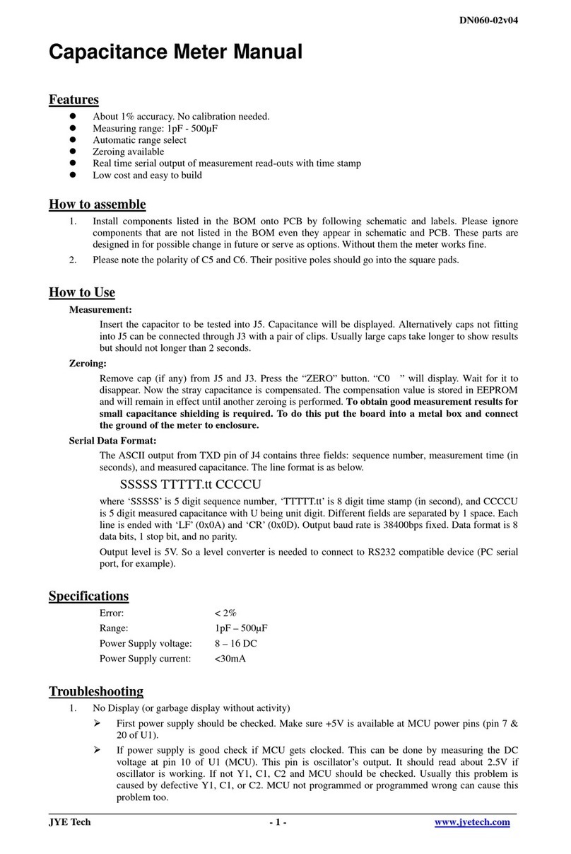
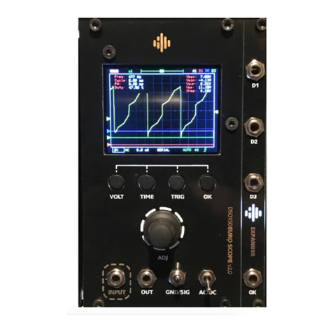
JYE Tech FG085 Function Generator User manual

DN085-01v06
JYE Tech-1-www.jyetech.com
FG085 miniDDS Function Generator
ManualofOperation
ApplicableModels:08501,08501K,08502K,08503,08503K, 08504K
ApplicableFirmwareVersion:1)113-08501-130orlater(forU5)
2)113-08502-050orlater(forU6)
1. Getting Started......................................................................................................................1
2. FrontPanelFeatures.............................................................................................................2
3. Connectors............................................................................................................................4
4. FG085 Operations.................................................................................................................6
ContinuousWaveform(CW)Mode...............................................................................................................6
Frequency..............................................................................................................................................7
Amplitude..............................................................................................................................................8
DC Offset...............................................................................................................................................8
IncrementalAdjustment.........................................................................................................................8
DutyCycle.............................................................................................................................................8
TriggerFunction....................................................................................................................................9
FrequencySweepingMode...........................................................................................................................9
Rangeand Rate....................................................................................................................................11
SweepDirection..................................................................................................................................12
TriggerFunction..................................................................................................................................12
SyncPulse Output...............................................................................................................................12
Amplitude............................................................................................................................................12
DC Offset.............................................................................................................................................12
ServoPositionMode...................................................................................................................................13
Pulse Widthand...................................................................................................................................14
Pulse Amplitude...................................................................................................................................14
Incrementand......................................................................................................................................14
ServoSignalSettings...........................................................................................................................15
ServoRun Mode..........................................................................................................................................15
States...................................................................................................................................................16
ChangeSettings...................................................................................................................................16
ArbitraryWaveformGeneration (AWG).....................................................................................................16
HowIt works.......................................................................................................................................16
DefineWaveformFile.........................................................................................................................17
DownloadWaveform...........................................................................................................................17
SelectUserWaveform.........................................................................................................................17
WaveformDownload...........................................................................................................................18
5. Firmware Upgrade..............................................................................................................18
6. TechnicalSupport...............................................................................................................19
7. Specifications......................................................................................................................19
Revision History..................................................................................................................................20
1. Getting Started
Introduction The FG085 isalowcostversatilefunction generatorcapableof
producing continuoussignal,frequencysweeping signal,servotest
signal,and userdefinedarbitrarysignals.Itwasdesigned asan
easy-to-usetoolforelectronichobbyists.The operation ofFG085
isextremelystraightforward. The following exampleswilllead
you step-by-step through some typicaluses.

DN085-01v06
JYE Tech-2-www.jyetech.com
Frontviewof08501/08502
DataEntry Setting ofFG085 signalparameters isdone byfirst pressing one
ofthe parameterkeys(F/T,AMP,orOFS).The display ofthat
parameterwillbe cleared and an underline isshown,indicating
place fornewvalue tobe typed in. Ifatthe momentyou hit a
parameterkeythe cursorisnotcurrentlyatthatparameterjust
press the keyone moretimetomake the underline shown. Then
enternewvalue using the DIGITkeys.Completeentrybyhitting
one ofthe UNITSkeys.Ifan errorismade attyping pressing
[ESC]keywill do backspacetocorrectit.Ifno moredigitsleft
when [ESC]ispressed it will exit DataEntryand displaythe
originalvalue.
Acursorfocusedparametercan alsobeadjusted incrementallyby
tuning [ADJ]dial.
Examples 1 )To setoutputfrequencyto 5KHzpressthe following keys:
[F/T][5][KHz]
2)Tochangeoutputwaveformtosquarewave press [WF]until
SQR”isshown.
3)Tosetoutputamplitude to3Vpeak-to-peakpressthe
followingkeys:
[AMP][3][V]
4 )To setDC offsetto -2.5Vpress the followingkeys
[OFS][+/-][2][.][5][V]
2. FrontPanelFeatures

DN085-01v06
JYE Tech-3-www.jyetech.com
Frontviewof08503
1 )PowerSwitch Thepowerswitch turnsthe FG085 on andoff.
2 )ParameterKeys The parameterkeysselectthe parametertobe entered. Ifcursor
is notcurrentlyataparameterpressingthe parameterkeywill
firstmove cursorto thatparameter.
3 )Digit Keys The numerickeypad allowsfordirectentryofthe FG085’s
parameters.Tochange aparametervalue simplypress the
parameterkey(if cursorisnotcurrentlyatthe parameterpress the
parameterkeytwice)and then type anewvalue. Entriesare
terminated bythe UNITSkeys.Ifan errorismade attyping press
[ESC]keytocorrectit(back space).Ifno moredigitsleft when
[ESC]ispressed it will exitDataEntryand displaytheprevious
value.
The [+/-]keymaybe pressed atanytime during numeric entry.
4 )Unit Keys TheUNITkeysareused toterminatenumericentries.Notethat
the unitkeysrepresentdifferentunitatdifferentparameter
entry.
UnderCWmode pressingunit keyswithoutfirstenteringdigits
willdisplayincrementalstepsizes.[Hz]keydisplaysfrequency
step size. [KHz]keydisplaystime step size.
5 )WaveformKey Thiskeyselectsoutputwaveform.Repeated pressing ofthis
keywill go through allavailable waveforms.
6 )ESCkey Thiskeybackspace typed digitsand/orexitcurrentstate.
7 )ADJDial By[ADJ]dialuserscanincrementallyadjustafocused
parameterup and down. Todo thisfirstpressingaparameter
keytomovecursortheparametertobe changed and then turn
the dial.
UnderCWorSweep modepressingthe dialwilltoggleTrigger
functionon oroff.
AtServomode pressingthe dialwillenter SettingChange

DN085-01v06
JYE Tech-4-www.jyetech.com
Frontviewof08501/08502
Boardviewof08503
state
8 )MODEKey ThiskeyselectsFG085’sworkingmodes.
9 )Frequency (Period)
Displayofcurrentoutputfrequencyorperiod.
10 )Waveform Displayofcurrentwaveformtype.
11 )DCOffset DisplayofcurrentoutputDCoffset.
12 )Amplitude Displayofcurrentoutputamplitude.
13 )Cursor Indication ofcurrentlyfocused parameter.Turning[ADJ]dial
will incrementallychange thisparameter.
When TriggerFunction ison the cursorchange to ‘*’.
14 FunctionOutput
(J4) Thisisthe frontoutputconnector. Itsoutputimpedance is50Ω.
3. Connectors

DN085-01v06
JYE Tech-5-www.jyetech.com
1 )PowerInput(J1) ThisistheDC powersupplyinputconnector.Itscentercore
shouldbe connected tothe positivepoleofpowersupply.
FG085 isspecified for14V –16VDC.Thecurrentcapacityof
powersupplyshould be greaterthan 200mAaverage.
2 )Function Output
(J5) Thisisthe backoutputconnector. Itsoutputimpedance is50Ω.
3 )USB(J10) ThisprovidesaconnectiontoPCforwaveformdatadownload
and instrumentcontrol.
4 )AlternativeUSB
(J7) Thisconnectorallowswiringthe USBconnection tosocketat
enclosure.
5 )Contrast
Adjustment Thisisa trimmerforLCDcontrastadjustment.
6 )U5Programming
Port(J8) Thisistheprogrammingheaderforthemaincontroller
ATmega168 (U5).
Pin-outDescription
Pin#
Signal
Name I/O Function
1 MOSI I U5programming
2 +5V PWR
3 NC - Noconnection
4 - - Reserved
5 nRST I U5programming
6 - - Reserved
7 SCK I U5programming
8 GND PWR
9 MISO O U5programming
10 GND PWR
7)U6Programming
Port(J6) Thisisthe programmingheaderforthe DDScorecontroller
ATmega48 (U6)
Pin-outDescription
Pin#
Signal
Name I/O Function
1 MOSI I U6programming
2 +5V PWR
3 Sync O Syncoutput(sweepingmode)
4 - - Reserved
5 nRST I U6programming
6 TrigIn I Trigger input
7 SCK I U6programming
8 GND PWR
9 MISO O U6programming
10 GND PWR

DN085-01v06
JYE Tech-6-www.jyetech.com
4. FG085 Operations
Power-on Pushdownthe powerswitch toturnon FG085. Itwillfirst
displaymodelname. Then manufacturer/vendornamefollows.
Afterdisplayingfirmwareversionstheunitenters normal
workingstate.
Output Theoutputamplitudedisplayisonlycorrectwhenload isin
highimpedance (much largerthan 50Ω).Ifload impedanceis
closeto50Ωtheoutputamplitudewillbelowerthen
displayed. Ifloadimpedanceis 50Ωtheoutputamplitude
will halfofthat displayed.
Mode Selection
FG085 can workinone offourdifferentmodes.Thesefour
modesare:
1) ContinuousWaveforms(CW)mode
2) FrequencySweepingmode
3) Servo Position mode
4) Servo Run mode
Pressing[Mode]button willdisplaythe mode selection menu.
Tuning[ADJ] will scroll throughthesemodes.The numberat
the lower-rightcornerindicatesmenu position. Pressing
[MODE]willselectthe mode displayed. Pressing[ESC]will
exitmode selection withoutchange.
ContinuousWaveform(CW)Mode
Inthismode the generatoroutputscontinuoussignalofselected waveforms.Signal
frequency, amplitude, and DCoffsetcan be independentlysetbyuser.
Screen Please referto Section 2 FrontPanelFeatures”.
WaveformSelection Waveformselection isdone bypressing[WF]key.

DN085-01v06
JYE Tech-7-www.jyetech.com
Frequency Frequencyissetbyfirstpressing[F/T].The currentdisplay
willbeerased and an underlineisshown, allowing userto
enternewvalue.Newvalue isentered withdigit keysand
followedbyone oftheUnitkeys.Alternatively,frequencycan
be changed incrementallybyusingthe[ADJ] dialwhen it is
focused. Theincrementalstep sizecan be settoany number
you want(see below).
Frequencycan alsobe setinperiod (indicated byletter ‘T’).
Press[F/T]keywilltogglebetweenfrequencyand period entry
mode.
FrequencyRange
Inspiteofthatnolimitedrangeissetforfrequencyentryit
shouldbeawareofthattherearepracticalrangesforoutput
frequencyduetothelowresolution8-bit DAC and slow
samplerate(2.5Msps).Outoftheserangessignalqualitywill
degradedaslargerdistortionsand jittersappear. The acceptable
rangesdepend on actualapplications.ForFG085output
frequencywithinthe followingrangeisconsideredreasonably
good formostapplications.
Function Range
Sine
Square
Triangle
Ramp
Staircase
0 –200KHz
0 –10KHz
0 –10KHz
0 –10KHz
0 –10KHz
MaximumFrequency Error
Maximumfrequencyerrordependson sampleclockand phase
accumulatorsize. ForFG085 the phaseaccumulatorsizeis24
bits.Twosamplingclocks,2.5Mspsand 10Ksps,areused.
Sampleclockisautomaticallyselectedbased on frequency
settingasshownin the table below.
Frequency Sampling Clock MaximumError
> 40Hz 2.5Msps 0.1490 Hz
40Hz 10Ksps 0.0005960 Hz

DN085-01v06
JYE Tech-8-www.jyetech.com
Amplitude Amplitude issetbyfirstpressing[AMP]key.Thecurrent
displaywill be erased andan underlineisshown, allowing
usertoenternewvalue.Newvalue isentered withDataEntry
keysand followedbyoneoftheUnitkeys.Alternatively,
amplitudecan bechangedincrementallybyusingtherotary
encoderwhen itisfocused.
Thedisplayed amplitude value ispeak-to-peakvalue.
The amplituderangeislimitedbythe DC offsetsettingsince
|Vac peak|+ |Vdc| ≤10 V(into High-Z).
D.C. Only
The outputofthe FG085can besettoaDClevelbyentering
amplitude of0V.When theamplitude issettozerothe A.C.
waveformwillbe completelyshutoff and the FG085 maybe used
asa DCvoltage source.
DCOffset DC offsetcan besetbyfirstpressing[OFS]key.Thecurrent
displaywill be erased andan underlineisshown, allowing
usertoenternewvalue.Newvalue isentered withDataEntry
keysand followedbyoneoftheUnitkeys.Alternatively,
offsetcan be changed incrementallybytuning[ADJ]when it
isfocused.
In general, the DCoffsetmayrange between ±5V, butit islimited
such that|Vacpeak|+|Vdc| ≤10 V(intoHigh-Z),or|Vac peak |+
|Vdc| ≤10 V(intoHIGH-Z).
Incremental
Adjustment
FG085’soutputfrequency,amplitude, and DC offsetcan be
changed incrementallyup and down byusing[ADJ]dial.Todo
thisfirstmovecursortotheparameteryou wanttochangeby
pressingaparameterkey andthen turnthe rotaryencoder
clock-wiseforincrementand counter-clock-wisefor
decrement.
Tip
Incrementalstep sizecanbe settoanyvalue. Todo this
directlyenterthe step size you wantand followby [Hz]or[ms]
button. [Hz]button setsstep sizeforfrequencyadjustment.
[ms]button setsstepsizefortimeadjustment.Press [Hz]or
[ms]withoutdigitswilldisplaycurrentfrequencyortimestep
size.
DutyCycle
(forsquarewaveform)
Dutycyclecanbe settovalue between 0%and 100%. Pressing
[.](the decimalpointkey)will displaycurrentdutycycle.
Press[.]keyagainthe displaywillbe erased andan underline
willshow,allowingusertoenternewvalue. Pressing anyof
the unit keysterminatesthe entry.Pressing[ESC]returnsto
normalCWmode display.
Notethatdutycycleonlytakeseffectforsquarewaveform.
Theacceptable value rangeis0 –100%with resolutionof1%.

DN085-01v06
JYE Tech-9-www.jyetech.com
Trigger Function Thetriggerfunction allowsusertocontrolthegeneratoroutput
byan externalsignal.WhentheexternalsignalisHIGHoutput
signalisstopped. Assoonasthetriggersignalchangesto
LOWoutputsignalresumes(see screen capture below).
TheexternalsignalmustbeTTLlevelcompatibleandapplied
to pin 6 ofJ6.
The triggerfunction can beturned on/offbypressing [ADJ]
dial.Whenitisonthecursor(normally ‘>’)willchangeto ‘*’
asindicator.
Theinitialphase ofoutputsignalateach triggerisconstant.
Notethatthetriggerinputispulled toHIGH internally.There
willbeno outputwhen theterminalisleftopen. Thisfeature
allowsusinga switch astriggersource.
Triggerwaveform
FrequencySweepingMode
Inthismode FG085 generatefrequencysweeping signals.The sweeping range andrateas
well assignalamplitude and DCoffsetare all independentlysetbyuser.
Screen
Turning[ADJ] orpressingdigit buttons[1],[2],[3],and [4]
will haveStartFreq, Stop Freq, Sweep Time, and TimeStep
Size displayed respectively.

DN085-01v06
JYE Tech-10-www.jyetech.com
WaveformSelection Waveformselection isdone bypressing[WF]key.
Normalsweeping
Bi-directionalsweeping

DN085-01v06
JYE Tech-11-www.jyetech.com
Range andRate
ofSweep Frequencysweepingisactuallyfrequencystepping.Four
parameters determine the frequencychange range and rate:
-Start Frequency
-Stop Frequency
-Sweep Time
-Time Step Size
The followingdrawingillustratestheirrelationships.
Frequencychange islinearonly. The smallesttime step is1ms.
Tochangetheseparametersfirstturn[ADJ]dialtoselectthe
parameteryou wanttochange. Thenpress[F/T]buttonto enter
values.
Tip
You can alsoquicklyaccess theseparametersby buttons[1],
[2], [3],and [4].Theirrelationshipsare:
[1]-Select/change StartFrequency
[2]-Select/change Stop Frequency
[3]-Select/change Sweep Time
[4]-Select/change Time Step Size
Notes:
1. Startand stopfrequenciescanonlybe entered inHzor
KHz.TheDDSsamplingclockselects2.5Mspsaslong as
sweepingmode isentered. Asaresult the frequency
resolutioninthismode is0.1490Hz(seeexplanationsin
CWmode).Theallowablefrequencyrangeis0 –999999
Hz.Keep inmind thatwhen frequencygoesbeyond
certain extend thesignalqualitydegradessignificantly.
2. Sweep timecan be enteredinSec ormSec. Itisalways
displayed in"mS".Theallowablesweep timerangeis1 –
999999 mS.
3. Timestep sizecan beentered inSecormSec. Itisalways
displayed in"mS".The allowed range is1 –65535 mS.
4. WhenSweep Timeislessthan TimeStep Sizetheactual
sweep timebecomes2*(TimeStep Size).Frequency
sweepinginthiscaseisdegraded tooutputtingstart and
stop frequencyalternatively.Thiscreatesan effectofFSK.

DN085-01v06
JYE Tech-12-www.jyetech.com
SweepDirection Normallyfrequencysweepingisfromstartfrequency(Fstart)
tostopfrequency(Fstop).Thisiscalled NormalSweeping.For
FG085 thesweepcan besettotwowaysweeping,i.e. it
sweepsfromFstarttoFstop, andthenfromFstop backto
Fstart.ThisiscallBi-directionalsweeping.
Toenablebi-directionalsweepingpress the[+/-]button. A
letter ‘B’will beshownon screen,indicatingbi-directional
sweep isenabled. Press[+/-]again willturnthe function off.
See photosabovefornormalsweepingand bi-directional
sweeping.
Forbi-directionalsweepingthe signalphaseiscontinuous
everywhere.
Trigger Function Triggerfunctionisalsoavailableforsweep mode. Whenthis
functionisenabled the generatoronlystartssweepingatfalling
edge oftriggersignal.
Press [ADJ]totoggletriggerfunction on/off.A ‘*’character
will be displayed on screen to indicate triggerfunction ison.
Unlikethe caseinCWmode whereoutputstopsassoon as
triggersignalchangestoHIGH,sweepingsignalwillfinisha
fullsweepeven triggersignalhasturnedHIGH beforetheend
ofa started sweep.
Sync Pulse Output Fornormalsweepingapositivesynchronouspulse isgenerated
atpin3ofJ6betweentheend ofasweep andthestartofnext
sweep. The pulse width isabout0.5ms.Itsamplitudeis5V. See
the photoofnormalsweepingabove.
Forbi-directionalsweeping the samepinoutputsLOW(0V)
levelwhen sweepingfromFstart toFstop andoutputsHIGH
(+5V)levelwhensweeping the otherwayaround(i.e. from
Fstop toFstart,seethe photoofbi-directionalsweeping
above).
Amplitude See the explanation of"Amplitude"in CW mode.
DCOffset See the explanation of"DC Offset"in CW mode.

DN085-01v06
JYE Tech-13-www.jyetech.com
ServoPosition Mode
Inthismode the generatoroutputsservocontrolsignalwithspecificpulsewidth,
amplitude,and cycle. Allthese parameters can be setindependentlybyuser.
Servo ControlSignal Thedrawingbelowshowsa servo controlsignal.
Typicallyservo signaltakesfollowingparameters:
1) Cycle:20ms
2) PulseWidth:1ms –2ms
3) Pulse Amplitude:5V
Thepulse widthdeterminesservo position.
Screens The photobelowshowsthescreensofServoPositionMode.
The firstscreen showspulsewidthinunitofmicrosecond. The
secondshowspulseamplitude inunitofvolt.Pressing[F/T]
will displaythe pulsewidthscreen andpressing[AMP]will
displaythe amplitude screen.

DN085-01v06
JYE Tech-14-www.jyetech.com
Pulse Width and
Cycle Atpulsewidthscreen pressing[F/T]willerasecurrentdisplay
and showan underline,allowingusertoenternewpulsewidth.
NewpulsewidthisenteredwithDataEntrykeysand followed
byone ofthe twoUnitkeys.The valueentered istreatedas
microsecond ifthe unitkey[Sec]isused, oras millisecond if
the unitkey[mSec]isused.
Pleasenotethattherangeofpulsewidththatusercanactually
enterislimited bytwovalues,SV.PWminand SV.PWmax. If
thepulsewidthyou inputisoutoftherangedefinedby
SV.PWminand SV.PWmax then theinputwillbe substituted
bythe limit numbers. Theselimitingvaluescanbemodifiedby
user(see below).The default valuesofSV.PWminand
SV.PWmax are 1000 uSec and 2000 uSec respectively.
Servo signalcycle canbe changed too. Thisisdone by
modifyingthe settingSV.CycleinSettingChangestate(see
below).
PulseAmplitude Atpulseamplitudescreenpressing[AMP]will erasecurrent
displayandshowan underline,allowingyou toenternew
pulseamplitude. Enternewpulseamplitude withDataEntry
keysand followbyone ofthe twoUnitkeys.The numberyou
enteredistreatedas volt if theunitkey[V]isused,oras mill
volt if theunitkey[mV]isused.
Like pulse width themaximumofamplitude thatusercanenter
is limited bythe value ofSV.AMPmax. Ifthe amplitude
entered isgreaterthan SV.AMPmax then theinputwillbe
substituted bySV.AMPmax. ThedefaultvalueofSV.AMPmax
is5.0V.Itcan alsobechanged in ChangeSetting”state(see
below).
Incrementand
Decrement
Ateitherpulsewidthscreenoramplitude screen usercan turn
[ADJ] toincrementallychangepulsewidthoramplitude. The
stepsizeofincrementalchangeforpulsewidthisdefinedby
SV.PWinc, anothersettingthatcanbe modified byuser(see
below).

DN085-01v06
JYE Tech-15-www.jyetech.com
Servo SignalSettings ServosignalsettingsareanumberofEEPROMstoredvalues
thataffectthe behaviourofservosignalgeneration. These
valuesareuserchangeable. Inordertochangethesevalues
pressing[ADJ] toenter SettingChange state. Thefollowing
screen will be displayed.
The top line showsasetting name. The bottomline showsits
value. Thenumberattop-rightcornerindicatescurrentmenu
position.
Tochangeasettingfirstscroll tothatsettingbyturning [ADJ].
Then press [F/T]to entera newvalue.
Pressing[ESC]willexit SettingChange state.
Restorefactorydefault
Factorydefault settingscanbe restored byscroll tothe last
itemand pressing[WF]key.
Thefollowingtableliststhe detailsaboutservo signalsettings.
Setting Descriptions Acceptable
Range Default
SV.PWmin Theminimumpulse
widthallowed 0 –26000uSec
1000
SV.PWmax Themaximumpulse
widthallowed 0 –26000uSec
2000
SV.PWmid Pulsewidth
corresponding to
servonurtureposition
0 –26000uSec
1500
SV.PWinc [ADJ] stepsize in
ServoPosmode0 –26000uSec
100
SV.RunStep Stepsize ofpulse
widthchangeinServo
Runmode 0 –26000uSec
100
SV.RunRate Durationofonestep
inServoRunmode 0 –6.5Second
0.1
SV.Cycle Servosignal cycle 0 –26000uSec
20000
SV.AMPmax
Themaximumpulse
amplitudeallowed 0 –10.0V 5.0V
When asettingissettoavalue outofacceptablerangethe
instrumentbehaviourisnotdefined.
ServoRun Mode
Inthismode the generatoroutputsservocontrolsignalwithchangingpulsewidth. The
pulsewidth change step, rate, and range are usersettable.

DN085-01v06
JYE Tech-16-www.jyetech.com
States When Servo Run mode isfirst entered itstaysat Ready state.
Inthisstateaconstantsignalwithpulsewidthequalto
SV.PWmin isgenerated.
When [WF]buttonispressed ittransfers to Running state.
InthisstatepulsewidthwillchangefromSV.PWminto
SV.PWmax incrementallyinstep definedbySV.RunStep.
Once itreachesSV.PWmax itwill immediatelychangeinthe
reversedirection,i.e. fromSV.PWmax toSV.PWmin
incrementallywiththesamestep size. Pulsewidthwillvaryin
thiswayuntil[WF]keyispressed.
When [WF]keyispressedinRunningstatethe generatorwill
enter Hold state, wherepulsewidthchangingstopsand
maintainsthe value atthe moment[WF]keyispressed.
Change Settings SettingsthataffectServoRun mode behaviourinclude
SV.PWmin, SV.PWmax, SV.RunStep, and SV.RunRate. These
settingscan bechanged byuser.Pleaserefertoparagraph titled
Servo SignalSettings”above fordetails.
ArbitraryWaveform Generation (AWG)
Withfirmwareversion 113-08501-130 (forU5)and 113-08502-050 (forU6)FG085 is
capable ofgeneratingarbitrarywaveformsdefined byuser.
HowIt works FG085 hasan EEPROMuserwaveformbufferinU5. When
waveformtype USER”isselected thedatainthisbufferwill
be loaded toDDScore(U6).Theuserwaveformbufferis
writable byPCsoftwarethrough USB.
Inordertogenerateuserdefinedwaveformthree stepsare
required:
1) Define a waveformfile
2) Download the waveformfile to userwaveformbuffer
3) Selectthe waveformand adjustparameters

DN085-01v06
JYE Tech-17-www.jyetech.com
Define WaveformFile
Theuserwaveformbufferconsistsof256 sampleswitheach
samplebeing8bits.Awaveformfiledefinesthevalueofeach
sampleinthe buffer.ThewaveformfileisingeneralCSV
(commaseparated value)format,which can be opened and
edited bymanyspreadsheetapplicationsand texteditors.A
waveformtemplatefilehasbeenprovided atJYETech web
site. Basedonthetemplateuserscan useanytexteditorto
createtheirownwaveformfileseasilyandquickly.For
detailed descriptionsofthe internalformatofFG085
waveformfilepleaserefertothe article FG085 Waveform
File Format”.
Download Waveform
ToFG085 WaveformisdownloadedtoFG085 bythejyeLab application
(see http://www.jyetech.com/Products/105/e105.php).Todo
this:
1) Launch jyeLab. ConnectFG085 toPCviaUSBand
clickthe Connect”buttontoestablishconnection.
MakesurecorrectCOMport andbaudrateare
selected.
2) Open the waveformfile you have prepared.
3) Selectmenu Generator-> Download”.
Pleaserefertothearticle HowToGenerateUserDefined
Waveform”(availableat http://www.jyetech.com).
SelectUser Waveform
Press[WF]button until USER”isdisplayed.

DN085-01v06
JYE Tech-18-www.jyetech.com
WaveformDownload
Protocol The waveformdownload followsasimpleprotocolwhich is
explained below.
1) Serialformat Baudrateisfixed at115200 bps.Data
formatis8-N-1. No flowcontrol.
2) Framestructure (multi-byte fieldsarealllittle endian)
3) Specialvalue[0xFE] Hexicalvalue 0xFEservesas
synchronouscharacterinthewaveformdownload. Itmust
be uniquetoensurecorrecttransmission/receiving.So if
another0xFEpresentsinthe fieldsofframesize, data
size, orwaveformdataa0x00 bytemustbe inserted right
afterit attransmission.
Offset
Field Name(size) Value
-1 Sync character(1 byte)
0xFE
0 Command (1 byte)
(write waveform) 0x14
1
Frame Size (2 bytes) Countfromthe
command byte to
the end of
waveformdata.
3 Reserved (1 byte) 0x00
4 Data Size (2 bytes) Numberofbytesto
be downloadedto
FG085 (usually
should be 256. Ifit
isgreaterthan 256
the extra data will
be ignored.)
6 Reserved (8 byte) 0x00
14 [waveformdata](as
specified in Data Size
field)
Data start
5. FirmwareUpgrade
Fromtimetotimetheremaybe aneed toupgradefirmwaresinordertoadd featuresor
improve performance. FG085 containstwoAVRmicro-controllers fromAtmel:
1) ATmega168PA(U5), which isthe main controllerofthe instrument.
2) ATmega48PA(U6), which isthe DDScore.
Toupgrade firmwarean AVRprogrammerwithcompatibleprogramming headerisrequired.
Forprogramming headerpin-outpleaserefertotablesundersection Connectors”.Ifthe
programming headeryou havehasadifferentpin-out.You needtore-routethe signalsto
make themmatch. (JYETech sUSBAVRProgrammer[PN:07302]isidealforFG085
programming. Please visit www.jyetech.com fordetails.)
Download updated firmwarefilesfromJYETech website(www.jyetech.com)and follow

DN085-01v06
JYE Tech-19-www.jyetech.com
instructionsofthe programmeryou have to carryoutfirmware upgrading.
AboutFuse Bits
AVRmicro-controllers containsomefusebitsthatconfigurethe chipforspecific applications.
Inmostcasesthesefusebitsshouldnotbe touched atfirmwareupgrading. Butif somehow
these bitsare changed theyshould be restoredasfollows.
1) ATmega168PA(U5)
Extended Fuse Byte: 0b00000111(0x07 )
High Fuse Byte: 0b11010110(0xD6 )
LowFuse Byte: 0b11100110(0xE6 )
2) ATmega48PA(U6), which isthe DDScore.
Extended Fuse Byte: 0b00000001 (0x01 )
High Fuse Byte: 0b11010110(0xD6 )
LowFuse Byte: 0b11100000(0xE0 )
6. TechnicalSupport
Foranytechnicalissuesorquestionsinusing the instrumentpleasecontactJYETech at
support@jyetech.com.OrpostyourquestionsatJYETech forumat
http://forum.jyetech.com.
7. Specifications
FrequencyRange 0 –200KHz (Sine)
0 –10K(all otherwaveforms)
FrequencyResolution 1Hz
PeriodResolution 1ms
MaximumFrequencyError CWMode:
0.1490 Hzwhen frequency>40 Hz (2.5Mspsclock)
0.0005960 Hz when frequency 40Hz (10Kspsclock)
Sweeping Mode:
0.1490 Hzwhen frequency>40 Hz (2.5Mspsclock)
AmplitudeRange 0 –10Vpeak-to-peak (when powersupplyvoltage >13V)
AmplitudeResolution 0.1V
DC OffsetRange -5V –+5V
OffsetResolution 40mV
SampleRate CWMode:
2.5Mspswhen frequency>40Hz
10Kspsclock when frequency 40Hz
Sweeping Mode:
2.5Msps
WaveformBufferSize 256 bytes
SampleResolution 8-bits
TriggerInputLevel High:3.5Vminimum
Low:1.5Vmaximum
OutputDelayatTrigger 5usmaximum(when no paneloperation)
SyncOutputLevel High:4.5Vminimumat10Kresistance load
Low:0.7Vmaximumat10mAintake current

DN085-01v06
JYE Tech-20-www.jyetech.com
OutputImpedance 50 ohm
PowerSupply14VDC(maximum16VDC)
CurrentConsumption <150mA(withoutloading)
Circuit BoardSize 155mm X55mm
Revision History
Version Date Summary
v05 2013.03.19 Updates toreflectnewfeatures infirmware113-08501-130
V06 2013.06.23 Correctedmistakeinthedescriptionforwaveformdownloadframe
structure.
Other manuals for FG085 Function Generator
4
Table of contents
Other JYE Tech Measuring Instrument manuals
Popular Measuring Instrument manuals by other brands

Axis Industries
Axis Industries QALCOSONIC HEAT 1 Technical description, installation and user instructions

SRS Labs
SRS Labs BGA244 quick start guide

Sequoia
Sequoia LISST-200X user manual

JONARD TOOLS
JONARD TOOLS FLS-55 instruction manual

HEDÜ
HEDÜ A412 manual

Rohde & Schwarz
Rohde & Schwarz ZNA Series user manual