Kübler LWLA.S Series Service manual

Deutsch (Originalfassung) - R60363.0009
Montage- und Bedienungsanleitung
LWL-Sendermodule: LWLA.SXX
LWL-Empfängermodule: LWLA.EXX
HINWEIS 1.1 Sicherheits- und Warnhinweise
Benutzen Sie diese LWL-Module nur
• bestimmungsgemäß
• in technisch einwandfreiem Zustand
• unter Beachtung der Bedienungsanlei-
tung und den allgemeinen Sicherheits-
bestimmungen.
1.2 Allgemeine Sicherheits- und Warnhinweise
1. Vor Durchführung von Installations- oder Wartungsarbeiten stellen Sie bitte sicher, dass die
LWL-Module von der Versorgungsspannung getrennt sind.
2. Setzen Sie die LWL-Module nur bestimmungsgemäß ein: In technisch einwandfreiem Zustand.
Unter Beachtung der Bedienungsanleitung und den allgemeinen Sicherheitsbestimmungen.
3. Beachten Sie länder- und anwendungsspezifische Bestimmungen.
4. Die Module sind nicht geeignet für den explosionsgeschützten Bereich und den Einsatzbereichen,
die in EN 61010 Teil 1 ausgeschlossen sind.
5. Die LWL-Module dürfen nur im ordnungsgemäß eingebautem Zustand entsprechend dem Kapitel
“Technische Daten” betrieben werden.
1.3 EG-Konformitätserklärung
Die LWL-Module der Typenreihe LWLA (Sender und Empfänger) stimmen mit folgenden Normen oder
normativen Dokumenten überein:
• EN 55011 Klasse B1
• EN 61000-6-2: 2006
2.1 Beschreibung:
Das System besteht aus einem LWL-Sender und einem LWL-Empfänger. Der LWL-Sender wandelt die
elektrischen Daten eines üblichen absoluten Drehgebers mit Synchronem Seriellem Interface (SSI)
in optische Lichtwellenleiter-Signale um. Das Empfängermodul wandelt die optischen Signale wieder
in elektrische SSI-Signale zurück. Über nur eine Glasfaser können die Absolutwerte bis zu 2000 m
zuverlässig übertragen werden. Mittels Drehschalter an der Modul-Frontseite kann die Auflösung
von 1 - 99 bit eingestellt werden. Beide Module besitzen LEDs, die eine umfangreiche Diagnostik von
Betriebsstörungen gestatten. Das Empfängermodul besitzt außerdem noch einen Alarm-Ausgang.
DEU - S. 1

DEU - S. 2
2.2 Die Module können in folgenden Varianten geliefert werden:
Bestellbezeichnung Funktion Versorgungsspannung Anschluss
LWLA.S10 LWL-Sender 10 … 30 V DC Klemmenanschluss
LWLA.S40 LWL-Sender 5 V DC ± 5% Klemmenanschluss
LWLA.S11 LWL-Sender 10 … 30 V DC Sub-D, 9-polig
LWLA.S41 LWL-Sender 5 V DC ± 5% Sub-D, 9-polig
LWLA.E10 LWL-Empfänger 10 … 30 V DC Klemmenanschluss
LWLA.E40 LWL-Empfänger 5 V DC ± 5% Klemmenanschluss
LWLA.E11 LWL-Empfänger 10 … 30 V DC Sub-D, 9-polig
LWLA.E41 LWL-Empfänger 5 V DC ± 5% Sub-D, 9-polig
3. Technische Daten
Bezeichnung Kennwert
Konstruktionsart Gehäuse für DIN-Schienenmontage nach
EN 50022
Abmessungen (B x L H) 19 x 110,8 x 92,3 mm
Gehäusefarbe RAL 7035 Lichtgrau
Schutzart nach EN 60529 IP40, Klemmen IP20
LWL-Anschluss ST-Stecker an der Gehäuseunterseite
Klemmen Berührungssicher, max. Aderquerschnitt:
0,14 -1,5 mm2, mit Aderendhülse 0,25 – 1 mm²
(nicht für HDSubD 15)
Glasfaser Multimode – Faser, 50/125 µm, 62,5/125 µm
Max. LWL-Übertragungslänge bei 850 nm 2000 m
Anzeige LWL-Synchronisation Empfänger Grüne LED leuchtet bei vorhandener Synchro-
nisation und blinkt bei Synchronisationsausfall
oder Unterbrechung des LWL-Empfängers
Abtastrate der Eingangssignale 10 MSamples/s
Versorgungsspannung 10 … 30 V bzw. 5 V ± 5%
Leistungsaufnahme (Einzelmodul) < 1 W
Verpolungsschutz der Betriebsspannung vorhanden
Elektrische Eingänge LWL-Sender bzw.
Ausgänge LWL-Empfänger
Takt C+ und C-, RS422
Daten D+ und D-, RS422
/Error NPN-Eingang am Sender,
Open-Drain-Ausgang am Empfänger
Max. Taktfrequenz LWL-Sender und
LWL-Empfänger
1 MHz
Signalverzögerung des Übertragungssystems
(ohne LWL)
< 500 ns
Optische Wellenlänge Infrarot 850 nm

Betriebstemperaturbereich -10°C bis +70°C
Störfestigkeit EN 61000-6-2
Störaussendung EN 55011 Klasse B1
4. Einsatzgebiete für die LWL-Module sind vor allem dann gegeben, wenn Signale in stark gestörter
Umgebung übertragen werden sollen, oder wenn aufgrund starker Erdpotentialdifferenzen zwischen
Signalquelle und Auswerteeinrichtung eine Potentialtrennung erforderlich ist.
Große Erdpotentialdifferenzen treten im Allgemeinen auch bei größerer räumlicher Entfernung
zwischen Drehgeber und SPS oder anderer Auswerteelektronik auf.
Das LWL-Kabel ist fehlersicher, d.h. es stellt bei Beschädigung keine Gefährdung dar. Da als lich-
temittierendes Bauelement kein Laser, sonder eine Lichtemitterdiode verwendet wird, geht auch
bei direkter Sicht auf den offenen Stecker oder die gebrochene Glasfaser keine Gefährdung von der
Übertragungsstrecke aus.
Der LWL kann durch explosionsgefährdete Bereiche verlegt werden.
Wenn mit der Potentialtrennung gleichzeitig eine Pegelumsetzung verbunden werden soll, so ist das
ohne weiteres möglich. Da alle Geräte dasselbe Signalübertragungsprotokoll auf dem LWL verwen-
den, kann jeder Sender mit jedem Empfänger kombiniert werden.
Eine Besonderheit des verwendeten Übertragungsverfahrens besteht daran, dass das SSI-Signal
ohne die störenden Umlaufverzögerungen (Round-Trip-Delay) zwischen Takt und Daten übertra-
gen wird. Hierdurch ist auch ein schnelles Auslesen des Gebers bei Leitungslängen über 2000 m
möglich.
5.1 Anschluss der Module
Die Takt- und Datenleitungen sind paarig zu führen, d.h. die beiden Adern eines Signals sind in
paarverseilten Kabeln zu führen. Eine Verwendung von bündelverseilten Kabeln (sog. Steuerkabel)
ist nicht zulässig, da hierbei weder die korrekte Signalübertragung noch die EMV-Kennwerte sicher-
gestellt werden können.
Die Kabelabschirmung ist beidseitig anzuschließen d.h. am Drehgeber und am LWL-Sender bzw. am
LWL-Empfänger und am Auswertegerät. Hierfür sind die Anschlüsse GND/Schirmung vorgesehen.
Die RS422-Ausgänge erfordern am Signalempfänger einen Differenzeingang mit einem Eingangswi-
derstand von 100 – 120 Ω. Die Ausgänge der Module sind nur bedingt kurzschlussfest, so dass ein
Kurzschluss untereinander oder gegen Masse unbedingt zu vermeiden ist.
Ein Überschreiten der Speisespannung für die Module mit 5 V Speisespannung über einen Wert von
ca. 6 V hinaus führt zum Abschmelzen der geräteinternen Sicherung und muss deshalb vermieden
werden.
Für die Module mit einer Speisespannung von 10 – 30 V liegt dieser Wert bei 33 V.
Die Sicherung ist beim Hersteller zu ersetzen. Der Versuch der Selbstreparatur führt zum Verlust der
Gewährleistung.
DEU - S. 3

DEU - S. 4
Zur Verbindung der Module untereinander können Multimode-LWL-Kabel 50/125 µm oder 62,5/125 µm
benutzt werden. Singlemode-LWL-Fasern sind nicht verwendbar.
Bewahren Sie die Staubschutzkappen der optischen Sender und Empfänger auf, und verschließen
Sie diese wieder damit, wenn kein LWL an den Modulen angeschlossen ist, um eine Verschmutzung
durch Staub oder andere Stoffe zu verhindern.
5.2 Anschlussbelegung
LWL-Sender
Anschlussart Klemmenanschluss
0Signal: 0 V +V C+ C- D+ D- Eingang/
Error –––H
Pin Buchse 1 2 3 4 5 6 7 8 9 10 11
Anschlussart Steckbarer Anschluss, Sub-D9
1Signal: 0 V +V Eingang/
Error D- D+ C- C+ – H
Pin Buchse 1 2 3 4 5 6 7 8 9
LWL-Empfänger
Anschlussart Klemmenanschluss
0Signal: 0 V +V C+ C- D+ D- Ausgang/
Error – – – H
Pin Buchse 1 2 3 4 5 6 7 8 9 10 11
Anschlussart Steckbarer Anschluss, Sub-D9
1Signal: 0 V +V Ausgang/
Error D- D+ C- C+ – H
Pin Buchse 1 2 3 4 5 6 7 8 9
Stromversorgung
Schraubklemme, 2-polig
Signal: 0 V +V Die Kontakte 1/2 des 2-poligen Steckverbinders sind
mit den Kontakten 1/2 des 11-poligen bzw. 1/2 des
Sub-D-Steckverbinders verbunden.
Pin Buchse 1 2
+V: Versorgungsspannung +V DC
0 V: Masse GND (0 V)
C+, C- : Taktsignal
D+, D- : Datensignal
H: Schirm

DEU - S. 5
6.1 Betrieb der Module - Sender
Nach dem Anschluss aller Leitungen sind die DIP-Schalter an der Gerätevorderseite des Senders
nach Abnehmen der Frontplatte (Rastung an der Oberseite mit einem Schraubendreher vorsichtig
nach unten drücken) entsprechend einzustellen.
Schalter SW 1 (DIP) Taktfrequenz für den Sensor/Drehgeber
Ein (on) 1 MHz
Aus (off) 500 kHz
Im Interesse einer schnellen Datenaktualisierung ist die höhere Frequenz zu wählen, wenn der
Sensor/Drehgeber das zulässt.
Schalter SW 2 (DIP) Pause zwischen den Taktimpulspaketen
Ein (on) 20 µs
Aus (off) 40 µs
Im Interesse einer schnellen Datenaktualisierung ist die kleinere Zeit zu wählen, sofern die Mo-
noflopzeit des Sensors/Drehgebers das zulässt. Der gewählte Wert muss größer als die Monoflopzeit
des Sensors bzw. Drehgebers sein.
Die rote LED dient zur Einstellkontrolle; wenn sie in der Stellung „Ein“ leuchtet, ist die Monoflopzeit
des angeschlossenen Gerätes größer als 20 µs.
Der Schalter ist dann auf „Aus“ zu stellen, wonach die rote LED verlöschen muss.
Mit den Drehschaltern „X 10“ und „X 1“ wird die erforderliche Taktimpulsanzahl eingestellt. Der
Einstellbereich der Schalter reicht von 1 bis 99 bit. In der Schalterstellung „00“ wird kein Impuls
ausgegeben; der Taktausgang verbleibt auf logisch High.
Beispiel: Angeschlossen ist ein Multiturn-Drehgeber mit 25 bit. Der Schalter „X 10“ ist in die Stellung
2 zu schalten, der Schalter „X 1“ in die Stellung 5.
LED-Signalisierung
LED Betriebszustand
Power (grün) Speisespannung liegt an und ist richtig gepolt
Error (rot) Die Monoflopzeit des angeschlossenen Gerätes ist größer als die
mit SW 2 eingestellte Zeit
6.2 Betrieb der Module – Empfänger
Der LWL-Empfänger erfordert keine Einstellungen. Er erhält die erforderlichen Steuerungsinformatio-
nen gemeinsam mit den Daten vom Sender.
An der angeschlossenen Steuerung ist dafür Sorge zu tragen, dass die korrekte Impulsanzahl zum
Auslesen des LWL-Empfängers abgegeben wird.
Ein Rundlaufbetrieb mit durchgehendem Takt der Steuerung ist nicht vorgesehen.

Wenn die Steuerung eine größere Impulsanzahl abgibt, als am Sender eingestellt, werden die Daten
richtig bis zur eingestellten Impulszahl ausgegeben. Alle weiteren Taktimpulse von der Steuerung
führen zur Ausgabe von Nullen am Datenausgang.
Die Monoflopzeit des LWL-Empfängers ist kleiner 12 µs.
LED-Signalisierung
LED Betriebszustand
Power (grün) leuchtet dauerhaft Speisespannung liegt an und ist richtig gepolt
Error (grün) blinkt Speisespannung des LWL-Senders fehlt oder der LWL ist
unterbrochen.
Error-Ausgang LWL-Empfänger
Wenn der /Error bzw. Statusausgang des Drehgebers/Sensors ausgewertet werden soll, ist dieser
an Pin 7 (11-Polig) bzw. Pin 3 (SubD) verfügbar. Er ist wie am Sensor /Drehgeber als Open-Drain-Aus-
gang ausgeführt und Low-aktiv.
Der Ausgang kann mit 50 mA belastet werden und besitzt einen Serienwiderstand von 51 Ω.
Für die ordnungsgemäße Funktion dieses Ausgangs ist die richtige Polung des angeschlossenen
Stromkreises zu beachten.
7. Maßbild
Maße in mm [inch]
19,0 [0.75]
19,0 [0.75]
73,5 [2.89]
75 [2.95]
92,3 [3.63]
21,7 [0.85]
DEU - S. 6

English (German is the original version) - R60363.0009
Mounting and Operating Instructions
Optical fibre transmitter modules: LWLA.SXX
Optical fibre receiver modules: LWLA.EXX
NOTICE 1.1 Notes on safety and warnings
Use these optical fibre modules only
• according to specification
• in technically trouble-free status
• subject to observation of the operating
instructions and the general safety
regulations.
1.2 General notes on safety and warnings
1. Before the implementation of installation or maintenance work, please ensure that the optical fibre
modules are disconnected from the power supply.
2. Use the optical fibre modules only in accordance with specifications:
In technically trouble-free status. Subject to observation of the operating instructions and the
general safety regulations.
3. Consider country-specific and application-specific stipulations.
4. The modules are not suitable for the explosion-protected area and those areas of application
which are excluded in EN 61010 Part 1.
5. The optical fibre modules may be operated only in the properly installed status, according to
chapter „Technical data“.
1.3 EC Declaration of Conformity
The optical fibre modules of the type series LWLA (transmitter and receiver) comply with the follo-
wing standards or normative documents:
• EN 55011 Class B1
• EN 61000-6-2: 2006
2.1 Description:
The system consists of a optical fibre transmitter and a optical fibre receiver.
The optical fibre transmitter converts the electrical data of a usual absolute rotation encoder equip-
ped with a synchronous series interface (SSI) into optical waveguide signals.
The receiver module converts the optical signals back into electrical SSI signals.
One single glass fibre is sufficient to transmit the absolute values reliably at a distance up to 2000 m.
By means of rotating switch on the module front side, the resolution can be adjusted by 1 - 99 bit.
Both modules are equipped with LED‘s which allow extensive diagnostics of operational failures.
In addition, the receiver module also has an alarm output.
ENG- P. 1

ENG- P. 2
2.2 The modules are available in the following variants:
Order code Function Power supply Connection
LWLA.S10 Optical fibre transmitter 10 … 30 V DC Terminal connection
LWLA.S40 Optical fibre transmitter 5 V DC ± 5% Terminal connection
LWLA.S11 Optical fibre transmitter 10 … 30 V DC Sub-D, 9-pole
LWLA.S41 Optical fibre transmitter 5 V DC ± 5% Sub-D, 9-pole
LWLA.E10 Optical fibre receiver 10 … 30 V DC Terminal connection
LWLA.E40 Optical fibre receiver 5 V DC ± 5% Terminal connection
LWLA.E11 Optical fibre receiver 10 … 30 V DC Sub-D, 9-pole
LWLA.E41 Optical fibre receiver 5 V DC ± 5% Sub-D, 9-pole
3. Technical data
Designation Characteristic value
Type Housing for DIN rail mounting according to
EN 50022
Dimensions (W x L H) 19 x 110.8 x 92.3 mm [0.75 x 4.36 x 3.63“]
Casing colour RAL 7035 light-gray
Protection type according to EN 60529 IP40, terminals IP20
Optical fibre connection ST plug connector on the casing bottom
Terminals Protected against contact, max. core
cross-section: 0.14 -1.5 mm2, with wire end
ferrule 0.25 - 1 mm² (not for HDSubD 15)
Glass fibre Multimode fibre, 50/125 µm, 62.5/125 µm
Max. optical fibre transfer length at 850 nm 2000 m
Indication optical fibre synchronization
receiver
Green LED lights up with the presence of
synchronization and flashes at synchronization
failure or interruption of the receiver optical fibre
Sampling rate of the input signals 10 MSamples/s
Supply voltage 10 … 30 V and 5 V ± 5%
Power consumption (individual module) < 1 W
Protection against incorrect polarity of the
operating voltage
Provided
Electrical inputs optical fibre transmitter and
outputs optical fibre receiver
Clock pulse C+ and C-, RS422
Data D+ and D-, RS422
/Error NPN input on the transmitter,
open-drain outlet on the receiver
Max. clock frequency of optical fibre transmit-
ter and optical fibre receiver
1 MHz
Signal delay of the transmission system
(without optical fibre)
< 500 ns

Optical wavelength 850 nm infrared
Operating temperature range -10°C ... +70°C [+14°F ... +158°F]
Interference immunity EN 61000-6-2
Radiated interference EN 55011 Class B1
4. Areas of application for the optical fibre modules are mainly when signals should be transferred in
an environment with strong interferences present, or when, due to high ground potential differences
between signal source and evaluating equipment, a separation of the potentials is necessary.
High ground potential differences generally also appear in case of large distances between the
rotation encoder and the PLC, or other processing electronics.
The optical fibre cable is fail-safe, i.e. there is no danger in case of damage. Since the light-emitting
component used is not a laser, but a light-emitting diode, the transmission line is totally safe, even
when looking directly into the opened connector or into the broken glass fibre.
The optical fibre cable can be routed through explosion-hazard areas.
If a level conversion should be simultaneously linked with the potential separation, this is possible
without any problem. Since all devices use the same signal transmission protocol on the optical fibre
cable, any transmitter can be combined with any receiver.
A specific feature of the transfer mode used is the fact that the SSI signal is transmitted without the
disturbing round-trip delays between the clock and the data. This also allows a quick reading of the
encoder even when using cable lengths exceeding 2000 m.
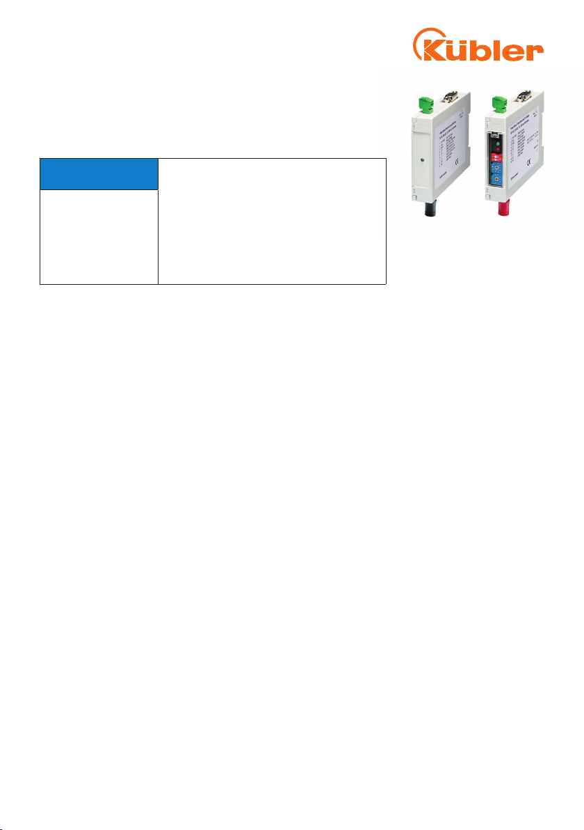
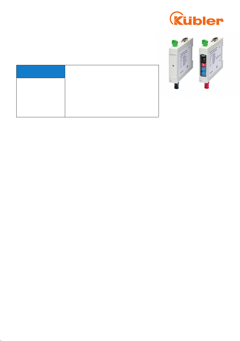
5.1 Connection of the modules
The clock pulse and data lines are to be routed in pairs, i.e. the two cores of a signal are to be routed
in paired cables. A utilization of bundle cables (so-called control cables) is not permissible, since in
this case neither the correct signal transmission nor the EMC characteristic values can be ensured.
The cable screening is to be connected on both sides, i.e. to the rotation encoder and to the optical
fibre transmitter or optical fibre receiver, and to the evaluator unit. For this, the connections are
provided with GND/screening.
The RS422-outputs on the control signal receiver require a differential input with an input impedance
of 100 - 120 Ω.
The outputs of the modules are short-circuit-proof to a limited extent only, so that it is
absolutely necessary to avoid a short circuit with each other or to ground.
Any exceeding of the power supply for the modules with 5 V power supply beyond a value of
approx. 6 V leads to the melting of the fuse located inside the unit and therefore must be avoided.
For the modules with a power supply of 10 - 30 V, this value is 33 V.
The fuse is to be replaced by the manufacturer. Any attempt to repair the device voids the guarantee.
For the connection of the modules to each other, 50/125 µm or µ 62.5/125 m multimode optical fibre
cables can be used. Single mode optic fibres are not usable.
Keep the dust protection caps of the optical transmitters and receivers and use them for closure
again if no optical fibre guide is connected to the modules, in order to prevent any dirt accumulation
through dust or other materials.
ENG - P. 3

ENG - P. 4
5.2 Terminal assignment
Optical fibre transmitter
Type of
connection
Terminal clamp
0
Signal: 0 V +V C+ C- D+ D- input/
Error –––H
Pin female
contact: 1 2 3 4 5 6 7 8 9 10 11
Type of
connection
Plug-in connector, Sub-D9
1
Signal: 0 V +V input/
Error D- D+ C- C+ – H
Pin female
contact: 1 2 3 4 5 6 7 8 9
Optical fibre receiver
Type of
connection
Terminal clamp
0
Signal: 0 V +V C+ C- D+ D- output/
Error – – – H
Pin female
contact: 1 2 3 4 5 6 7 8 9 10 11
Type of
connection
Plug-in connector, Sub-D9
1
Signal: 0 V +V output/
Error D- D+ C- C+ – H
Pin female
contact: 1 2 3 4 5 6 7 8 9
Power supply
Screw terminal, 2-pole
Signal: 0 V +V Contacts 1/2 of the 2-pin plug-in screw terminal
are connected to contacts 1/2 of the 11-pin plug-in
screw terminal or with contacts 1/2 of the Sub-D
connector.
Pin female
contact:
1 2
+V: Power supply +V DC
0 V: Power supply ground GND (0 V)
C+, C- : Clock signal
D+, D- : Data signal
H: Shield

ENG - P. 5
6.1 Operation of the modules - transmitter
After the connection of all lines, the DIP switches are to be correspondingly adjusted on the device
front side of the transmitter after removing the front panel (carefully press latch on the upper side
down with a screwdriver).
Switch SW 1 (DIP) Clock frequency for the sensor/rotation encoder
On 1 MHz
Off 500 kHz
In the interests of a fast data update, the higher frequency is to be selected if the sensor/rotation
encoder allows this.
Switch SW 2 (DIP) Pause between the clock pulse packages
On 20 µs
Off 40 µs
In the interests of a fast data update, the shorter time is to be selected, provided that the monoflop
time of the sensor/rotation encoder allows this. The selected value must be larger than the monoflop
time of the sensor or rotation encoder.
The red LED is used for the adjusting control; when it lights up in the setting „On“, the monoflop time
of the connected device is larger than 20 µs.
The switch is then to be set to „Off“, after which the red LED must go out.
With the rotating switches „X 10“ and „X 1“, the necessary clock pulse number is adjusted. The
adjustment range of the switches extends from 1 to 99 bit. In the switch position „00“, no pulse is
output; the clock output remains on logical High.
Example: A multi-turn rotation encoder with 25 bit is connected. The switch „X 10“ is to be switched
to the setting 2, the switch „X 1“ to the setting 5.
LED signalling
LED Operating state
Power (green) Power supply applied and is poled correctly
Error (red) The monoflop time of the connected device is larger than the
time adjusted with SW 2
6.2 Operation of the module - receiver
The optical fibre receiver does not require any adjustments. It is provided with the necessary control
information together with the data of the transmitter.
At the connected control, it is therefore to be ensured that the correct pulse number for the read-out
of the optical fibre receiver is submitted.
A concentric running operation with continuous clock pulse of the control is not provided.
If the control submits a greater pulse number than set-adjusted on the transmitter, the data is output

Kübler Group
Fritz Kübler GmbH
Schuberstr. 47
D-78054 Villingen-Schwenningen
Germany
Phone: +49 7720 3903-0
Fax: +49 7720 21564
info@kuebler.com
www.kuebler.com
R60363.0009
19,0 [0.75]
19,0 [0.75]
73,5 [2.89]
75 [2.95]
92,3 [3.63]
21,7 [0.85]
correctly up to the adjusted pulse number. All further clock pulses from the control lead to the output
of zeroes at the data output.
The monoflop time of the optical fibre receiver is shorter than 12 µs.
LED signalling
LED Operating state
Power (green) lights up
permanently
Power supply applied and is poled correctly
Power (green) flashes Power supply of the optical fibre transmitter is missing or the
optical fibre guide is interrupted.
Optical fibre receiver error output
If the /Error and Status output of the rotation encoder/sensor should be evaluated, this is available on
Pin 7 (11-pole) and Pin 3 (SubD). As on the sensor / rotation encoder, it is implemented as an open-
drain outlet and Low active.
The output can be loaded with 50 mA and has a series resistance of 51 Ω.
For the proper functioning of this output, the correct polarity of the connected electric circuit is to be
ensured.
7. Dimension
Dimensions in mm [inch]
Other manuals for LWLA.S Series
1
This manual suits for next models
9
Table of contents
Languages:
Other Kübler Receiver manuals
Popular Receiver manuals by other brands

Denon
Denon AVR-X2000 owner's manual

Circle Prime Manufacturing
Circle Prime Manufacturing CP-03276 installation instructions

Magellan
Magellan Trailblazer XL reference guide

Williams Sound
Williams Sound Digi-Wave DLR 400 ALK Quick setup guide

Harman Kardon
Harman Kardon AVR 140 owner's manual

Harman Kardon
Harman Kardon AVR 630 quick start guide