Kübler LWLS.A1 Service manual

Montage- und Bedienungsanleitung
LWL- Sendermodule: LWLS.A1, LWLS.A4
LWL- Empfängermodule: LWLE.A1, LWLE.A4
Beschreibung:
Das System besteht aus einem LWL-Sender und einem LWL-Empfänger.
Der LWL-Sender wandelt die elektrischen Daten eines üblichen absoluten
Drehgebers mit Synchronem Seriellem Interface (SSI) in optische
Lichtwellenleiter-Signale um.
Das Empfängermodul wandelt die optischen Signale wieder in elektrische
SSI-Signale zurück.
Über nur eine Glasfaser können die Absolutwerte bis zu 1500 m zuverlässig
übertragen werden.
Mittels Schiebeschalter an der Modul-Frontseite kann die Auflösung 13 Bit für
Singleturngeber oder 25 Bit für Multiturngeber eingestellt werden.
Beide Module besitzen LEDs, die eine umfangreiche Diagnostik von
Betriebsstörungen gestatten.
Der Empfängermodul besitzt außerdem noch einen Sammelalarm-Ausgang mit
galvanischer Trennung (Optokoppler).
Die Module können in folgenden Varianten geliefert werden:
Bestellbezeichnung Pegel an Takt- und
Datenleitungen Funktion Versorgungsspannung
LWLS.A1 RS 422 LWL-Sender 10 – 30 VDC
LWLS.A4 RS 422 LWL-Sender 5 VDC ± 5%
LWLE.A1 RS 422 LWL-Empfänger 10 – 30 VDC
LWLE.A4 RS 422 LWL-Empfänger 5 VDC ± 5%
Einsatzgebiete für die LWL-Module sind vor allem dann gegeben, wenn Signale in stark gestörter Umgebung
übertragen werden sollen, oder wenn aufgrund starker Erdpotentialdifferenzen zwischen Signalquelle und
Auswerteeinrichtung eine Potentialtrennung erforderlich ist.
Große Erdpotentialdifferenzen treten im Allgemeinen auch bei größerer räumlicher Entfernung zwischen
Drehgeber und SPS oder anderer Auswerteelektronik auf.
Das LWL-Kabel ist fehlersicher, d.h. es stellt bei Beschädigung keine Gefährdung dar. Da als lichtemittierendes
Bauelement kein Laser, sonder eine Lichtemitterdiode verwendet wird, geht auch bei direkter Sicht auf den
offenen Stecker oder die gebrochene Glasfaser keine Gefährdung von der Übertragungsstrecke aus.
Der LWL kann durch explosionsgefährdete Bereiche verlegt werden.
Wenn mit der Potentialtrennung gleichzeitig eine Pegelumsetzung verbunden werden soll, so ist das ohne
weiteres möglich. Da alle Geräte dasselbe Signalübertragungsprotokoll auf dem LWL verwenden, kann jeder
Sender mit jedem Empfänger kombiniert werden.
Eine Besonderheit des verwendeten Übertragungsverfahrens besteht daran, dass das SSI-Signal ohne die
störenden Umlaufverzögerungen (Round-Trip-Delay) zwischen Takt und Daten übertragen wird. Hierdurch ist
auch ein schnelles Auslesen des Gebers bei Leitungslängen über 1500 m möglich.
Anschluss der Module
LWLS
Pin Signal Beschreibung
1 0 V (Masse)
2 +Ub
3 +T
4 -T
Zum
Drehgeber
5 +D
6 -D
Vom
Drehgeber
7 0 V (Masse)
8 +Ub
Von der
Stromversorgung
An die Anschlüsse 1 – 6 kann der Drehgeber über ein
konfektioniertes Kabel angeschlossen werden. Die
Nummerierung der Anschlüsse entspricht der des
Drehgebers.
Die Stromversorgung ist an die Klemmen 7 und 8
anzuschließen.
Deutsch
R60356.0009 06 20 09 ES

LWLE
Klemme Signal Beschreibung
1 0 V (Masse)
2 +Ub
Von der
Stromversorgung
3 +D
4 -D
Zur Steuerung
5 +T
6 -T
Von der Steuerung
7 Emitter(-)
8 Kollektor(+)
Optokoppler-
Alarmausgang
Wenn andere Kabel zwischen Drehgeber und LWLS als die konfektionierten verwendet werden, so ist
folgendes zu beachten:
Die Ein- und Ausgangsleitungen sind grundsätzlich in paarverseilten Kabeln zu führen.
Eine Verwendung von bündelverseilten Kabeln (sog. Steuerkabel) ist nicht zulässig, da hierbei weder die
korrekte Signalübertragung noch die EMV-Kennwerte sichergestellt werden können.
Die Kabelabschirmung ist beidseitig anzuschließen d.h. am Drehgeber und am LWLS.
Bei allen Modulen ist sicherzustellen, dass der Signalempfänger einen Differenzeingang mit einem Eingangswiderstand
von 100 – 120 ȍbesitzt.
Zur Verbindung der Module untereinander können Multimode-LWL-Kabel 50/125 µm oder 62,5/125 µm benutzt werden.
Als Steckverbinder wird der Typ ST benutzt
Singlemode- LWL- Fasern sind nicht geeignet.
Betrieb Modul LWLS
Nach dem Anschließen aller Leitungen ist der DIP-Schalter an der Gerätevorderseite entsprechend einzustellen:
Schalterstellung Drehgebertype Anzahl der Taktimpulse
ein (on) Single Turn 13
aus Multiturn 25
Signalisierung LWLS
LED Betriebszustand
Power (grün) Speisespannung liegt an und ist richtig gepolt
Error (rot) xEine der oder beide Taktleitungen zum Drehgeber haben einen
Kurzschluss nach Masse oder untereinander;
xUnterbrechung in den Daten- oder Taktleitungen;
xWenn die LED beim Drehen des Drehgebers aufleuchtet und wieder
verlischt, ist der Schiebeschalter in der falschen Stellung oder der
Drehgeber benötigt eine andere Taktimpulszahl
Wenn ein Kurzschluss erkannt wird, ist die Betriebsspannung vom Eingang des LWLS abzutrennen und der Fehler
zu beseitigen. Der Treiberschaltkreis für die Taktleitungen ist nicht dauerhaft kurzschlussfest.
Schlüsse zur Betriebsspannung sind unbedingt zu vermeiden, da der Treiber hierbei sofort beschädigt werden kann.
Betrieb Modul LWLE
Der LWLE erfordert keine Einstellungen. Die Anzahl der Drehgeber-Taktimpulse (13 oder 25) wird am
LWLS eingestellt und zum LWLE neben dem Datenpaket mit übertragen. Lediglich an der angeschlossenen Steuerung ist
dafür Sorge zu tragen, dass die richtige Impulszahl (13 oder 25) zum Auslesen des LWLE abgegeben wird.
Ein Rundlaufbetrieb mit durchlaufendem Takt von der Steuerung ist möglich. Jedoch wird hierbei der Absolutwert
nicht aktualisiert, da die Monoflopzeit unterschritten wird. Die Monoflopzeit des LWLE beträgt 16 µs.
Signalisierung LWLE
LED Betriebszustand
Power (grün)
leuchtet dauerhaft
xSpeisespannung des LWLE-SSI liegt an und ist richtig gepolt
Power (grün)
blinkt
xSpeisespannung des LWLS-SSI fehlt oder
xLWL unterbrochen oder nicht richtig gesteckt
Remote Error (rot)
Duplizierung der Error-LED
des LWLS-SSI
xEine der oder beide Taktleitungen zum Drehgeber haben einen Kurzschluss
nach Masse oder untereinander;
xUnterbrechung in den Daten- oder Taktleitungen des Drehgebers;
xWenn die LED beim Drehen des Drehgebers aufleuchtet und wieder
verlischt, ist der Schiebeschalter in der falschen Stellung oder der
Drehgeber benötigt eine andere Taktimpulszahl
Local Error (rot)
xEine der oder beide Datenleitungen zur Steuerung haben einen Kurzschluss
nach Masse oder untereinander;
xUnterbrechung oder Kurzschluss in den Taktleitungen von der Steuerung

Wenn ein Kurzschluss erkannt wird, ist die Betriebsspannung vom Eingang des LWLE abzutrennen und der Fehler
zu beseitigen. Der Treiberschaltkreis für die Taktleitungen ist nicht dauerhaft kurzschlussfest.
Schlüsse zur Betriebsspannung sind unbedingt zu vermeiden, da der Treiber hierbei sofort beschädigt werden kann.
Der LWLE besitzt einen Sammelalarm- Ausgang . Dieser ist mit einem Optokoppler galvanisch von allen anderen
Schaltungsteilen getrennt.
Alle Fehlermeldungen des LWLS und LWLE gemäß Tabelle werden hierbei Oder-verknüpft und führen zur Durchsteuerung des
Optokoppler- Transistorausgangs.
Der Ausgang kann mit 50 mA belastet werden und besitzt einen internen Serienwiderstand von 33 . Die Spannungsfestigkeit
beträgt 40 V. Die Emitter-Kollektor-Strecke ist mit einer antiparallelen Schutzdiode beschaltet, so dass für die ordnungsgemäße
Funktion des Alarmausganges auf die richtige Polung des angeschlossenen Stromkreises zu achten ist.
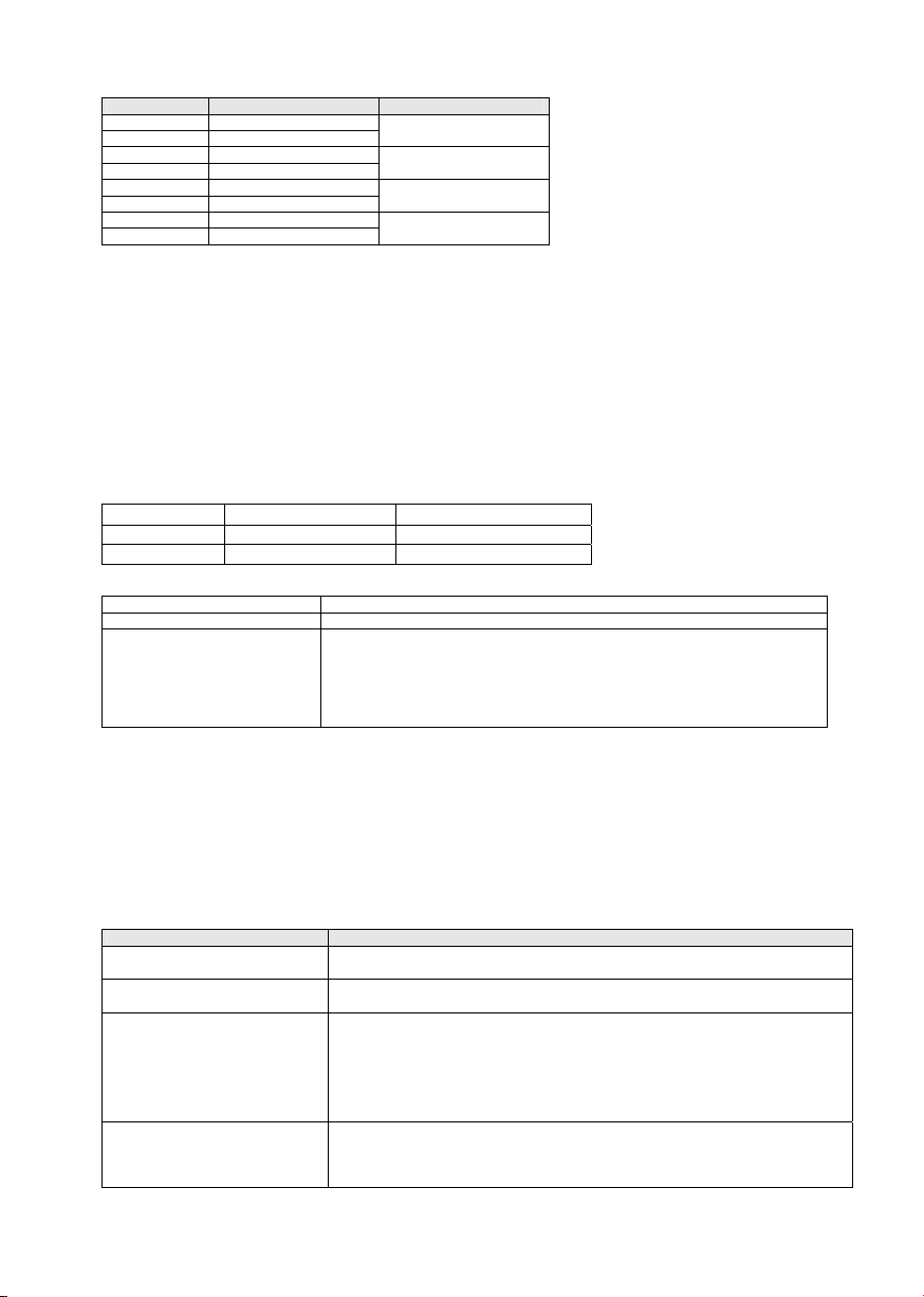
Alarmausgang LWLE
Klemme Stromkreis
7Emitter des Optokopplers, Minusseite des Signalstromkreises
8 Kollektor des Optokopplers, Plusseite des Signalstromkreises
LWLS und LWLE
Alle Module besitzen einen Verpolungsschutz, der eine Beschädigung bei Verpolung ausschließt.
Bei beiden Modulen ist darauf zu achten, dass der LWL-Stecker richtig gesteckt und der Bajonettverschluss verriegelt ist.
Weiterhin ist zu beachten, dass der verwendete ST-Stecker polarisiert ist und eine Orientierungsnase besitzt, die
in den Schlitz der optischen Sender und Empfänger einzuführen ist. Keinesfalls Gewalt anwenden!
Bewahren Sie die Staubschutzkappen der optischen Sender und Empfänger auf, und verschließen Sie diese wieder damit,
wenn kein LWL an den Modulen angeschlossen ist, um eine Verschmutzung durch Staub oder andere Stoffe zu verhindern.
Die Ausgänge der Module sind nur bedingt kurzschlussfest, so dass ein Kurzschluss untereinander oder gegen Masse
unbedingt zu vermeiden ist.
Ein Überschreiten der Speisespannung für die Module LWLS.A4 und LWLE.A4 über einen Wert von 6 V hinaus führt zum
Abschmelzen der geräteinternen Sicherung und muss deshalb vermieden werden.
Für die Module LWLS.A1 und LWLE.A1 liegt dieser Wert bei 33 V.
Die Sicherung ist beim Hersteller zu ersetzen. Der Versuch der Selbstreparatur führt zum Verlust der Gewährleistung.
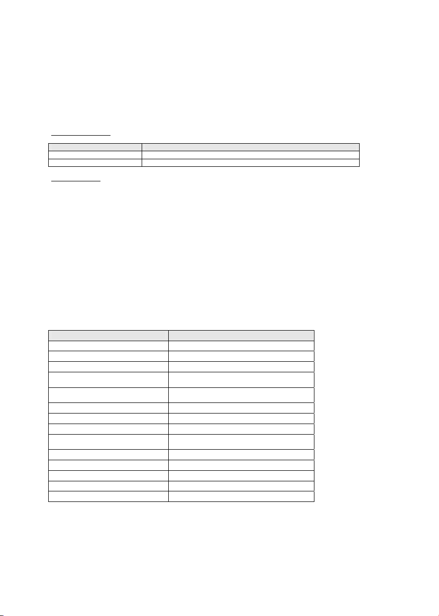
Technische Daten
Bezeichnung Kennwert
Gehäuse Hutschienenmontage nach EN 50 022
Abmessungen (B x L H) 22,5 x 110,8 x 88,4 mm
Schutzart: IP 40, Klemmen IP 20
LWL-Anschluss ST- Stecker, 13 mm, 9 mm, an
der Gehäuseunterseite
Klemmen: Berührungssicher, max.
Adernquerschnitt: 2,5 mm2
Glasfaser Multimode – Faser, 50/125 µm; 62,5/125 µm
Max. LWL-Übertragungslänge 1500 m
Versorgungsspannung 10 – 30 VDC bzw. 5 VDC ± 5%
Verpolungsschutz Betriebsspannung vorhanden
Elektrische Ein- und Ausgänge -T, +T sowie –D, +D
max. Taktfrequenz LWLS und LWLE 500 kHz
Optische Wellenlänge 840 nm (Infrarot)
Optische Übertragungsrate 120 Mbit/s
Betriebstemperaturbereich -10 °C bis +60 °C

Abme ssungen
4 5 6
1 2 3
78
75,0
22,5
12,3
110,8
63,0
88,4
Gehäusematerial: Polyamid PA6.6, UL 94 VO
Gehäusefarbe: hellgrau, RAL 7035
Druckfarbe: schwarz
Schutzart Gehäuse: IP 40/EN 60529
Schutzart Klemmen: IP 20/EN 60529
Wichtige Hinweise:
Sicherheitshinweise
Bevor das Gerät in Betrieb genommen wird, Nennspannung beachten, siehe Typenschild. Überzeugen Sie sich,
dass die Anschlussleitungen nicht beschädigt und während der Verdrahtung des Gerätes spannungsfrei sind.
Reinigung
Der Zähler kann, im spannungslosen Zustand, mit einem trockenen oder mit Seifenlösung angefeuchteten Tuch
gesäubert werden. Auf keinen Fall dürfen ätzende oder lösungsmittelhaltige Substanzen zur Reinigung verwendet
werden.
Wartung
Die Module LWLS und LWLE sind wartungsfrei. Bei Schaden durch Transport oder Lagerung dürfen vom Anwender
keine Reparaturen vorgenommen werden.
Gewährleistung
Beim Öffnen der Geräte erlischt der Gewährleistungsanspruch.
Bestimmungsgemäßer Gebrauch
Die ortsüblichen Normen, Richtlinien, Bestimmungen und Vorschriften sind einzuhalten. Die Installation der
Zähler darf nur von fachkundigem und entsprechend geschultem Personal erfolgen. Die Module sind bei
Lagerung, Transport vor Feuchtigkeit zu schützen sowie nicht außerhalb der spezifizierten technischen Daten
zu betreiben.
EG-Konformitätserklärung
Die LWL- Module der Typenreihe LWLE und LWLS stimmen mit folgenden Normen oder normativen Dokumenten
überein:
ŶEN 55011 Klasse B
ŶEN 61000-6-2: 2006
R60356.0009 06 20 09 ES

En
g
lish
Mounting and Operating Instructions
Optical fibre transmitter modules: LWLS.A1, LWLS.A4
Optical fibre receiver modules: LWLE.A1, LWLE.A4
Description:
The system is made of an optical fibre transmitter and of an optical fibre receiver.
The optical fibre transmitter module converts the electrical data of a usual
absolute encoder equipped with a synchronous serial interface (SSI) into
optical fibre signals.
The optical fibre receiver module converts the optical signals back into
electrical SSI signals.
One single glass fibre is sufficient to transmit the absolute values reliably at a
distance up to 1500 m.
Aslide switch on the front side of the module allows setting the resolution:
13 bits for singleturn encoders or 25 bits for multiturn encoders.
Both modules are equipped with LED’s, allowing a wide diagnosis of operating
troubles.
In addition, the receiver module also has a general alarm output with galvanic
isolation (optocoupler).
The modules a
r
e available in the followin
g
variants:
Order code Level for clock
and data lines Function Supply voltage
LWLS.A1 RS 422 Optical fibre transmitter 10 – 30 VDC
LWLS.A4 RS 422 Optical fibre transmitter 5 VDC ± 5%
LWLE.A1 RS 422 Optical fibre receiver 10 – 30 VDC
LWLE.A4 RS 422 Optical fibre receiver 5 VDC ± 5%
The optical fibre modules are mainly used when signals are to be transmitted in environments with strong
interferences or when, due to high ground potential differences between the signal source and the signal
processing equipment, potential separation is necessary.
High ground potential differences generally appear also in case of large distances between the encoder and the
PLC or any other processing electronics.
The optical fibre cable is failure-safe: it does not constitute any danger in case of damage. Since the light-emitting
component used is not a laser, but a light-emitting diode, the transmission line is totally safe, even when looking
directly into the opened connector or into the broken glass fibre.
The optical fibre cable can be routed through explosive areas.
If necessary, a level conversion can be linked with the potential separation without problem. Since all devices use
the same signal transmission protocol on the optical fibre cable, any transmitter can be combined with any
receiver.
A specific feature of the transfer mode used is the fact that the SSI signal is transmitted without the troubles due to
the round-trip delays between the clock and the data. This allows also a quick reading of the encoder even when
using cable lengths exceeding 1500 m.
Connection of the modules
LWLS
Terminal Signal Description
1 0 V (earth)
2 +Ub
3 +T
4 -T
To the
encoder
5 +D
6 -D
From the
encoder
7 0 V (earth)
8 +Ub
From the
power supply
The encoder can be connected to the terminals 1 – 6 by
means of a confectioned cable. The numbering of the
terminals corresponds to that of the encoder.
The power supply must be connected to terminals 7 and
8
Englisch
R60356.0009 06 20 09 ES

LWLE
Terminal Signal Description
1 0 V (earth)
2 +Ub
From the
power supply
3 +D
4 -D
To the control
5 +T
6 -T
From the control
7 Emitter(-)
8 Collector(+)
Optocoupler
alarm output
If other cables than the confectioned ones are to be used between the encoder and the LWLS, the following is to
be taken into consideration:
As a principle, the input and output cables must be routed using paired cables.
The use of bundle wires (so-called control cables) is not allowed, since this could not guarantee the correct transmission of the
signal, nor the EMC features.
The cable shield must be connected at both ends, at the encoder and at the optical fibre transmitter.
For all modules, make sure that the signal receiver has a differential input with an input resistance of 100 – 120 ȍ.
The modules may be connected together using 50/125 µm or 62.5/125 µm multimode optical fibre cables.
Use ST-type connectors.
Single-mode optical fibre cables cannot be used.
Operation – LWLS module
After connecting all lines, set the DIP switch located on the front side of the device as required:
Switch position Encoder type Number of clock pulses
on Singleturn 13
off Multiturn 25
Signalling - LWLS
LED Operatingcondition
Power (green) Power supply is applied and polarity is correct
Error (red) xOne or both clock lines to the encoder is or are short-circuited with the
earth or together;
xInterruption of the data or clock lines;
xWhen the LED lights up and then goes off when the encoder rotates, the
slide switch is in the wrong position or the encoder requires another
number of clock pulses.
When a short-circuit is detected, the operating voltage must be disconnected from the input of the LWLS, and the failure must
be removed. The driver circuit of the clock lines is not permanently short-circuit resistant.
Short-circuits with the operating voltage must absolutely be avoided, since they might damage the driver immediately.
Operation – LWLE module
The LWLE module requires no setting. The number of encoder clock pulses (13 or 25) is set at the LWLS and transmitted to the
LWLE in addition to the data package. Care must simply be taken in order to set the right number of pulses (13 or 25) on the
connected control to enable it to read the LWLE data.
Uninterrupted sending of clock signals by the control for constant encoder reading is possible. However, the absolute value will not
be updated in this case, since the delay will be shorter than the monoflop time. The monoflop time of the LWLE is 16 µs.
Signalling LWLE
LED Operating condition
Power (green)
Steadily on
xSupply voltage is applied to the LWLE SSI and polarity is correct
Power (green)
blinking
xSupply voltage of the LWLS SSI missing or
xOptical fibre interrupted or wrongly connected
Remote Error (red
Duplication of the error LED
of the LWLS SSI
xOne or both clock lines to the encoder is or are short-circuited with the earth
or together;
xInterruption of the data or clock lines of the encoder;
xWhen the LED lights up and then goes off when the encoder rotates, the
slide switch is in the wrong position or the encoder requires another number
of clock pulses.
Local Error (red)
xOne or both data lines to the control is or are short-circuited wit the earth or
together;
xInterruption or short-circuit of the clock lines of the control

When a short-circuit is detected, the operating voltage must be disconnected from the input of the LWLE, and the failure must
be removed. The driver circuit of the clock lines is not permanently short-circuit resistant.
Short-circuits with the operating voltage must absolutely be avoided, since they might damage the driver immediately.
The LWLE has a general alarm output. This output is isolated galvanically from all other circuit elements by means of an
optocoupler.
All error messages of the LWLS and of the LWLE according to the table are combined in a logical OR function and set the
transistor output of the optocoupler in passing mode.
The output withstands 50 mA and has an own internal series resistor of 33 . The withstand voltage is 40 V. The emitter-collector
line includes an antiparallel protector diode, so that care must be taken of the correct polarity of the connected circuit in order to
ensure the correct operation of the alarm output.
Alarm output - LWLE
Terminal Circuit
7Optocoupler emitter, minus side of the signal circuit
8Optocoupler collector, plus side of the signal circuit
LWLS and LWLE
All modules are protected against reversed polarity, which avoids any damage in case of wrong polarity.
Make sure on both modules that the optical fibre connector is correctly in place and that the bayonet catch is locked.
It must also be noted that the ST connector used is indexed and has an orientation spigot which must engage the slots of the
optical emitter and of the optical receiver. Never force!
Keep the dust protection covers of the optical transmitters and receivers, and put them back in place when no optical fibre cable is
connected to the modules, in order to avoid any soiling by dust or any other substance.
The outputs of the modules only are short-circuit proof in certain conditions; avoid imperatively short-circuits between modules or
with the earth.
Exceeding the supply voltage of the modules LWLS.A4 and LWLE.A4 above a value of 6 V leads to the destruction of the fuse
located inside of the device and must thus be avoided.
For the modules LWLS.A1 and LWLE.A1, this value is 33 V.
The fuse must be replaced in the manufacturer’s factory. Any attempt to repair the device will void the guarantee.
Technical characteristics
Designation Characteristic
Construction Housing for DIN rail mounting acc. to EN 50 022
Dimensions (W x L x H) 22.5 x 110.8 x 88.4 mm
Protection: IP 40, terminals IP 20
Optical fibre connection ST connector, 13 mm, 9 mm,
on the bottom side of the housing
Terminals: Protected against contact,
max. conductor diameter: 2.5 mm2
Glass fibre Multimode fibre, 50/125 µm; 62,5/125 µm
Max. optical transmission distance 1500 m
Supply voltage 10 – 30 VDC or 5 VDC ± 5%
Operating voltage
reverse connection protection Available
Electrical inputs and outputs -T, +T and –D, +D
Max. clock frequency LWLS and LWLE 500 kHz
Optical wavelength 840 nm (infrared)
Optical transmission rate 120 Mbit/s
Operating temperature range -10 °C to +60 °C

Dimensions
4 5 6
1 2 3
78
75,0
22,5
12,3
110,8
63,0
88,4
Gehäusematerial: Polyamid PA6.6, UL 94 VO
Gehäusefarbe: hellgrau, RAL 7035
Druckfarbe: schwarz
Schutzart Gehäuse: IP 40/EN 60529
Schutzart Klemmen: IP 20/EN 60529
Housing material: Polyamide PA 6.6, UL 94 VO
Housing colour: light gray, RAL 7035
Printed text colour: black
Housing protection: IP 40/EN 60529
Terminals protection: IP 20/EN60529
Important remarks:
Safety instructions
Before commissioning the device, make sure that the supply voltage fits the indications of the name plate. Make sure
that the connecting lines are not damaged and are not live when wiring the device.
Cleaning
When switched off, the device can be cleaned using a dry cloth or a cloth moistened with a soapy solution. In no
case use aggressive or solvent-containing substances to clean the device.
Maintenance
The LWLS and LWLE modules are maintenance-free. It is forbidden for the user to carry out any repair work in case
of damages due to transportation or storage.
Guarantee
The guarantee voids if the device is opened.
Approved purpose
The local standards, directives, provisions and regulations must be adhered to. The installation of the devices
can only be performed by a competent staff trained to that end. The modules must be protected against
humidity during storage and transportation. They shall not be used outside of the ranges specified in the
technical data.
CE declaration of conformity
The optical fibre modules of the series LWLE and LWLS comply with the following standards or normative documents:
ŶEN 55011 Class B
ŶEN 61000-6-2: 2006
R60356.0009 06 20 09 ES
This manual suits for next models
3
Table of contents
Languages:
Other Kübler Receiver manuals