K-Line Irrigation G-Set User manual

K-Line™ G-Set™ Irrigation
Solid Set Irrigation for pasture
Installation and user manual
K-Line Irrigation NA
4270 Hollywood Road
St. Joseph, MI 49085
Toll Free 866-665-5463
Local 269-429-3000
Email [email protected]
www.k-linena.com
May 2017

K-Line™ G-Set™ irrigation
2
K-Line™ G-Set™ Irrigation
G-Set is a solid set fixed system that minimizes “labor” for the
day to day operation of irrigation.
It is suitable for all land areas, and is not restricted by the
shape, terrain, size or topography.
The controller is an individual, battery operated unit. The
G-Set units are to be synchronized and programed prior to
installation and any future adjustments are done individually
or on a group basis.
This installation manual is a guide to the best practice of
installing G-Set. Failure to follow these instructions can
lead to instability and poor performance.
G-Set Sub-Main and “T” Installation 3
G-Set Pod Assembly 4
Connecting G-Set Pod to Main Line 5
Programming the Controller 6-7
Installing Battery Controller
and Solar Panel 8-10
Completing the G-Set Pod
& Installing Guard 11
G-Set is an irrigation ‘system’, and to
achieve the desired outcome, must be
approached and treated as such, and
not an accumulation of components.
Contents

3
K-Line™ G-Set Unit Installation
The system is comprised of a main-line telescoping through the property,
feeding 2” sub-mains.Your dealer design map will show sub-mains with
“T”s attached approximatley 3 feet adjacent to the predetermined G-Set
locations. The G-Set locations are designed around layout coverage and
terrain. A 40mm feed line will extend from the “T” to the G-Set side entry.
The main and sub-main pipes are to be installed (trenched in) below
maximum frost level. A combination of a GPS survey and visual
assessment will be required to ensure correct placement of the G-Set to
achieve the desired coverage (DU).
1
During the install of the sub-main,
2” x 2” snap “T”s with 2” x 1 1/2” slip x thread
bushings would have been glued 3’ adjacent to
and angled towards the GPS location chosen
for the G-Set.
1
Sub-Main and “T” Installation
G-Set install tools
A1 1/4” hole saw – for the tapping saddle installation
B
5/16” socket adaptor bit – for screws
C
3/8" drive battery operated drill
C
A
B
A 40mm Male adapter (KLAMC40) with a
length of 40mm tubing long enough to reach
1 foot above the ground surface are to be
tightened into this threaded bushing. Enough
room must be left at this hole to flex the
40mm tubing to the G-Set. This hole will be
completely filled in when finished.
2
It is desirable to dig the hole required for the G-Set no bigger than
necessary to allow the installation and compaction of soil around the
pod.The larger the hole, the harder and more time consuming it is to
get good compaction and secure placement.

4
K-Line™ G-Set™ Unit Installation
1
Before starting the sub
assembly, find the 1 1/2” x 11”
long nipple and 1 1/2” base
plug in the parts pack and apply
teflon tape to the threaded ends.
2Next the sprinkler, valve and
base are to be pre-assembled
with the shell before the G-Set is
positioned in the hole. Screw the
11” nipple into the perpendicular
hole of the threaded “T” at the
base of the assembly as pictured
in the diagram at right using two
pipe wrenches. Tighten firmly
with one pipe wrench holding the
internal pipe assembly.
3Lay the G-Set shell on it’s side and
insert the assembly into the shell.
Line up the 11” nipple portion of
the valve assembly into the 2” hole
in the side and very bottom of the
shell. While holding this assembly
in place, line up the bottom hole
of the threaded “T” in the valve
assembly with the center hole in
the bottom of the shell. Insert the
base plug through the bottom of the
shell from the outside and screw it
into the threaded “T” at the bottom
of the valve/nipple assembly.
Tighten the base plug firmly to
secure the pipe assembly to the
G-set housing.
4
Next tighten the sprinkler to the valve
assembly. Then finally attach the
1 1/2” x 40mm female adapter elbow
onto the end of the 1 1/2” nipple after
applying teflon tap on the threads.
Insert plug up through
hole and screw into
base of main structure Bottom view

5
K-Line™ G-Set Unit Side Entry Installation
Side Entry Installation 1
2
1
2
A 14” deep hole should be dug at the GPS location per
the dealer plan. This hole should be approximately 36”
from the 2” PVC sub-main “T”. Compact the hole opposite
the connection side so the G-Set fits tightly into the hole.
(You will need room on the connection side to attach your
40mm feed pipe.)
Lower the G-Set pod into the hole while
lining up the 40mm entension with the elbow
adapter on the G-set. Mark the pipe length
required while the G-set is positioned correctly
in the hole. (Normally, you will have to cut
some of the 40mm tubing to fit). Lift the G-Set
out of the hole. Cut the 40mm pipe to the
determined length. Ensure all below ground
connections are tight. Insert the G-Set back
into the hole while lining up the 40mm pipe to
the compression fit 90° angle adapter. Check
to see that your 40mm tubing is seated deeply
into its connector before tightening. Ensure the
rim of the pod is parallel with the lay of the land
for optimum sprinkler coverage. Back fill and
compact hole. The side G-Set holes should be
at ground level.
Ground
level
3Locate the first half of the
cover/support (The one with the rectangular
indent in the bottom) and place it into the
pod with the dish/indent facing either south
or the best orientation to capture maximum
sunshine hours. Then loosely screw it into
place using the screws provided. (This cover
will be tightened after the controller cables
are fed through in a later step.) The assembly
should now be ready to install the control
system.
3
14” DEEP

6
K-Line™ G-Set™ Irrigation
G-Set Controller Features
• Up to two operations per day
• Easy installation and programming
• Waterproof and weather resistant
• Battery powered; no need for
electrical hookup.
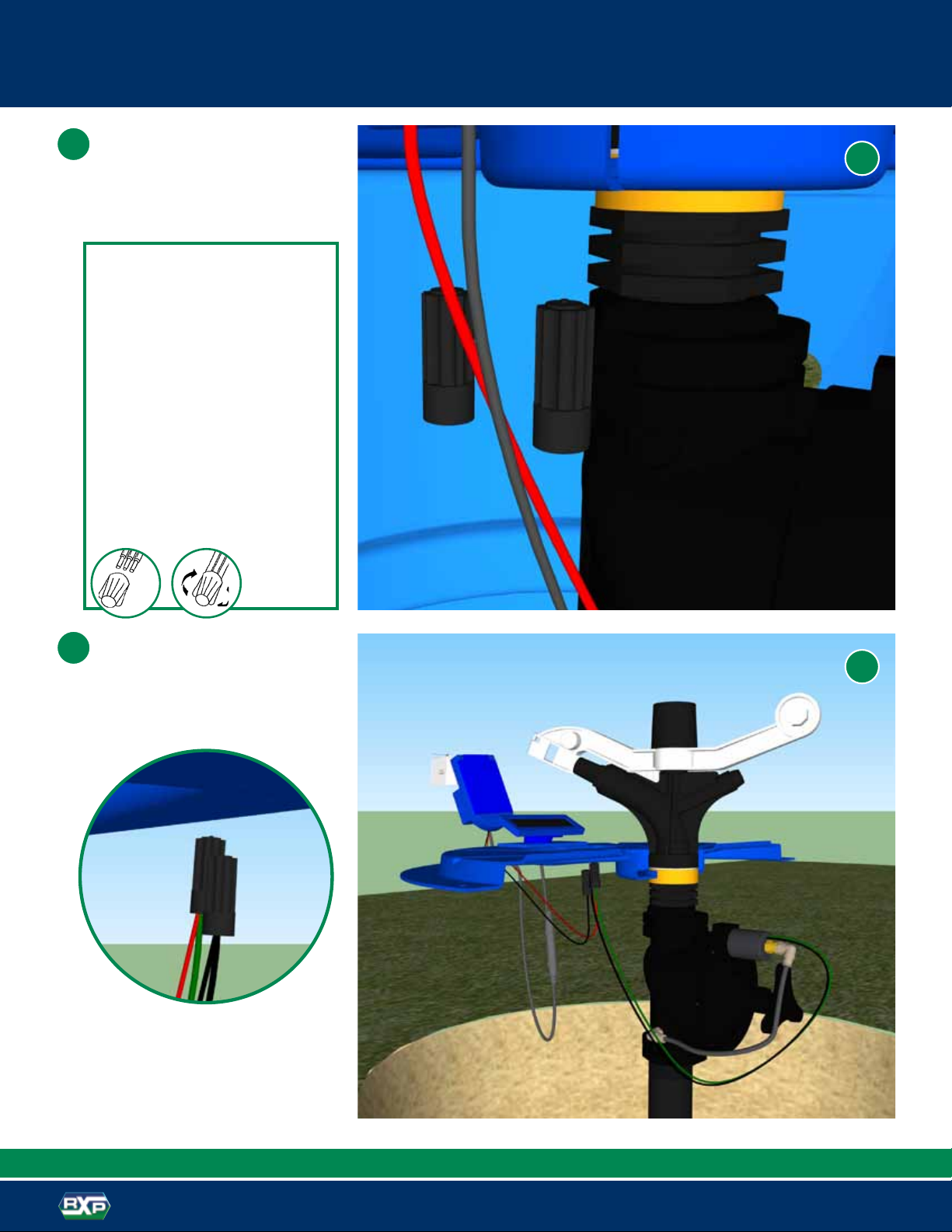
Parts Identification
1. Top cover
2. Controller display
3. Solenoid
4. Controller
If the screen is blank, press
MODE to activate.
1. Press MODE for several
seconds until the following
screen appears,
the minutes will be flashing.
On this screen the minutes refer
to the amount of time you wish
to irrigate.
2. Use the and buttons to adjust minutes
3. Press SET to continue (you have just completed adjusting the
duration).
The following screen appears,
START 1 flashes:
4. To select START 1, press
and then SET, the minutes will
be flashing. To deselect START
1press and then SET,
START 1 will disappear and
START 2 flashes.
Repeat steps 4-7for START 2.
Following is a brief description of the Controller buttons.
See the following sections for further details.
MODE button - Quick presses of the MODE button turn the
controller off. Longer presses of the MODE button put the
controller in programming mode.
SET button - Press the SET button to set a function and
proceed.
Use these buttons to increase and decrease
schedule functions or select / deselect functions.
1. Occasionally a valve opens in transit. To ensure that the valve
is closed before programming, make sure the controller is
not set to OFF (If it is set to OFF, press briefly on the MODE
button to turn it on).
2. Press and SET simultaneously to open the valve.
3. Press SET and to close the valve.
You are now ready to program the controller.
To manually open the valve, make sure the controller is in
operating mode and press and SET simultaneously.
The irrigation will continue until the interval defined as passed.
If the irrigation duration has been set to zero, the valve will close
after one minute.
To stop irrigating, press and SET simultaneously.
Getting Started Programming the Controller
Setting the Irrigation duration
and START Times
Basic Controller Functions
Valve Operation
Manual Operation
15
6
2
3
4
Meaning of Controller icons
NOTE: Quick presses of the
MODE button turns
the controller on or off.
Longer presses of the
MODE button put the
controller in programming mode.

7
K-Line™ G-Set™ Irrigation
Trouble Shooting
Service Information
Setting the Clock
Maintenance
9
10
7
8
Battery Installation
Replace the battery at the start of
each irrigation season or when the
low battery symbol appears.
Use a 9V alkaline top quality battery
only.
1. Use a Phillips screwdriver to remove
the 4 battery cover screws.
2. Remove the battery cover
and seal.
3. Replace the battery.
4. After reattaching the seal put the
cover back and secure with the
4 screws.
Continue Setting the Irrigation
duration and START Times
5. Use the and to set
the START 1 minutes.
6. Press SET to continue
7 Use the and
to set
the START 1 hour
8. Press SET to continue
9. Repeat steps 4-8for START 2
You have just adjusted the irrigation program.
Baccara products are guaranteed to be free from defects in material and
workmanship for a period of one year from the date of delivery.
This guarantee does not apply where equipment is not used and
installed strictly in accordance with Baccara specifications and Users
Guide. Neither does it apply to failures caused by lightning strikes or
damage due to freezing temperatures or mechanical causes (e.g. lawn
mowers). Baccara is not liable for indirect, incidental or consequential
damage in connection with the use of equipment.
To receive guarantee benefits, customers should return defective units
along with a copy of the receipt of purchase to the nearest Baccara
distributor.
Baccara reserves the right to alter, modify or redesign its products,
pricing and warranty at all times without creating any liability for the
obsolescence of customer inventory of such parts or products.This
manufacturer guarantee policy may apply differently in different countries.
Press two long presses
on the MODE button until
the time adjustment icon
appears (the minutes will be
flashing):
2. Use the and buttons to
adjust minutes.
3. Press SET to continue
4. Use the and
to adjust the hours.
5. Press SET to return to operating mode.
Factory Default Setting
The controller comes with the following factory default settings:
Duration: 10 minutes
Start: 1, 12:00
When replacing seal,
push seal tabs into slots.

8
K-Line™ G-Set™ Battery Controller Installation
1
2
ABC
Connect the controller to the bracket. Connect
the bracket to the shell as indicated in the
picture with two screws from the inside of the
shell. Feed the controller cables under the
loosely attached cover support and tighten
the screws.
The cover should be placed before the
mounting of the screws holding the
lid to the G-Set.
Programming of the controller should be
completed before mounting
1
Battery controller (C1013)
install tools
APhillips head screwdriver
B
1 1/4” hole saw – for the attachment of
the socket to the lid of the G-Set
CDrill
2
Cover

9
K-Line™ G-Set™ Solar Panel Installation
4Feed the solar panel cable through the newly drilled hole.
Insert the solar panel base into the hole. Screw two screws
into either side of the inserted base of the solar panel.
Screw a retaining tek screw into the back from the top.
Insert to left to fix rotation.
Double check at this point that the solar panel will be facing
the direction that captures maximum sunshine hours.
Plug the cable from the solar panel to the cable from the
controller as shown.
Solar panel connector
5
4
5
33
3
Drill a 1 1/4” hole at the back of the rectangular updent
to mount the solar panel. Ensure that the solar panel
faces the best solar collection direction. Generally this
will be southerly. The best outcome generally is a bit to
the West of South, or East of South.
Retaining
screw
placement

10
3
K-Line™ G-Set™ Solenoid Wiring Assembly
Using the included wire nuts, you are
able to connect the solenoid (latch)
coil to the controller.
Connect black latch wire to black
controller wire and the green latch
wire to the red controller wire. This
is achieved by the use of the wire
nuts included.
Red to green wire
Black to black wire
This is how the C1013 controller should be mounted.
Installing the Connectors
1. Strip wires ½"
2. Align frayed strands or conductors
3. Do not pre-twist. Place stripped
wires together with ends even.
4. Twist connector onto wires pushing
firmly until hand-tight.
DO NOT over torque
5. Swipe excess sealant in and
around conductors.
Do not reuse
6
6
7
7

11
K-Line™ G-Set™ Top Cover and Guard Installation
2
Locate the second half of the cover/sprinkler
support and screw into place ensuring the
base of the sprinkler is firmly held around the
orange slip ring on the sprinkler. Three screws
are supplied to attach the second cover half.
Install the stockguard on the shell with the four
remaining screws and the unit is ready to use.
2
11
NOTE: If using a battery drill to install the screws, avoid
stripping the plastic shell of the G-set by not over-tightening.
Install the bearing in the center hole of the
stock guard. This black plastic bearing is
designed to keep cattle from pushing down
on the guard and collapsing the guard onto
the sprinkler.
3
3
2
Bottom Guard Plug
Top Guard Cap

12
May 2017
K-Line Irrigation NA
4270 Hollywood Road
St. Joseph, MI 49085
Toll Free 866-665-5463
Email [email protected]
www.k-linena.com
Popular Irrigation System manuals by other brands

Perrot
Perrot ZN23-3D Maintenance and operating instructions

Autopot
Autopot easy2grow 80 Set-up guidelines

Johnson Controls
Johnson Controls Tyco TY720 quick start guide

Fiskars
Fiskars 1023659 instructions

Toro
Toro DT35 Series Installation & service instructions

Reliable
Reliable DDX PrePaK Instructions for installation, operation care and maintenance