Nelson F75 Big Gun Instruction Manual

4 8311 Screw,
#8-32 x .375,
Self Tapping Pan Head
Dri e Vane
Dri e Arm
Nozzle
Arm Weight
Lower Bearing Assembly
Nelson Irrigation Corporation 848 Airport Rd. Walla Walla, WA 99362-2271 U A Tel: 509.525.7660 Fax: 509.525.7907 [email protected] Web site: www.nelsonirrigation.com
F75 BIG GUN®
OM-F75-2
F75 BIG GUN® OPERATION & MAINTENANCE INSTRUCTIONS
SET UP FOR OPERATION:
1. Install desired Taper Ring size in ring nozzle cap. The ring
nozzle cap can be sufficiently tightened by hand.
2. Install sprinkler on riser of proper size and stability.
NOTE ON LUBRICATION: The F75 sprinkler is lifetime
lubricated and does not re uire periodic lubrication. The ball
bearings in the H.D. lower bearing operate in a water resistant
lubricant that is packed in the housing cavities and retained
by seals. If repair of the lower bearing is done, it is recom-
mended to use Nelson #6143 lubricant or a good grade of
water resistant lubricant such as Lubriplate 130-AA.
BE CAREFUL: Read operating instructions before operating
sprinkler or making any adjustments. Never make adjustments
or perform service while sprinkler is in operation. Stand clear
of operating sprinkler. Stand clear of high velocity water
stream. Never direct water stream onto roadway or electrical
transmission lines.
WARRANTY AND DISCLAIMER: Nelson Big Gun® Sprinklers are warrante for one year from ate of original sale to be free of efective materials an
workmanship when use within the working specifications for which the pro uct was esigne an un er normal use an service. The manufacturer
assumes no responsibility for installation, is limite solely to replacement or repair of efective parts, an the manufacturer will not be liable for any crop
or other consequential amages resulting from any efects or breach of warranty. THIS WARRANTY IS EXPRESSLY IN LIEU OF ALL OTHER WARRANTIES,
EXPRESS OR IMPLIED, INCLUDING THE WARRANTIES OF MERCHANTABILITY AND FITNESS FOR PARTICULAR PURPOSES AND OF ALL OTHER OBLIGATIONS
OR LIABILITIES OF MANUFACTURER. No agent, employee or representative of the manufacturer has authority to waive, alter or a to the provision of
the warranty, nor to make any representations or warranty not containe herein.
The F75 is available in fixed trajectory angles of 21°,
24°, 27°
6598 Ball Bearing
10730 Spacer, Teflon Coated
10377 O-Ring, Non-Standard
.459 I.D. x .040 C.S.
F75 DRIVE ARM ASSEMBLY COMPONENTS
10192 Spacer
6603 Nut
10231 Cap Assembly, Arm Bearing
Consists of: 1 10190 Cap, Arm Bearing
1 6563 O-Ring
10191 Cam
10194 Spacer
10214 Spacer 6600 Seal
10189 Spring 6598 Ball Bearing

Nelson Irrigation Corporation 848 Airport Rd. Walla Walla, WA 99362-2271 U A Tel: 509.525.7660 Fax: 509.525.7907 in[email protected] Web site: www.nelsonirrigation.com
6/04
F75 MAINTENANCE
SEE FRONT FOR DRIVE ARM ASSEMBLY COMPONENTS / SEE PARTS LIST FOR COMPLETE PARTS LIST AND DESCRIPTIONS
DISASSEMBLY/REASSEMBLY
STEP 1 (Drive Arm)
Remo e four #8311 screws
holding #10231 cap. Using an
11/16 socket, remo e the
#6603 nut from left side of arm.
STEP 2
Holding the barrell, pull arm
from the right side until it is free
from hub.
STEP (Drive Arm)
Inspect both left and right #6598
ball bearings. Replace if worn
or corroded. Inspect #6600 seal
as well. Lubricate seal with
silicon grease prior to
reassembly.
STEP 4
Assure the #10377 O-ring and
#10730 Spacer is on the dri e
arm shaft. Push the shaft all the
way into the right arm hub. From
the left side slide onto the arm
shaft, in sequence, the #10214
spacer, #6598 bearing, #10194
spacer, #10191 cam.
STEP 5
Make sure the #10191 cam is
correctly keyed into the slot on
the dri e arm shaft. Notice the
correct orientation of the finger
on the cam for proper arm
operation.
STEP 6
Continue the sequence of sliding
onto the dri e arm shaft the
#10192 spacer and the #10189
spring. Notice the hook end of
the spring goes in first so the
spring wire loops around the
finger of the #10191 cam.
STEP 7
Thread on #6603 nut. Torque to
25 ft. lbs. using the 11/16 socket
(metric torque = 34 NM or 3.5
MKG).
STEP 8
Replace the lubricant. Replace
cap making sure that the notch
engages the spring tab. Replace
screws. Assure the dri e arm
mo es freely.
#10730
Spacer
#6598
Ball Bearing
Dri e
Arm
Finger on
#10191
Cam
#10189
Spring Hook
Spring Tab fits
into cap notch

Nelson Irrigation Corporation 848 Airport Rd. Walla Walla, WA 99362-2271 U A Tel: 509.525.7660 Fax: 509.525.7907 in[email protected] Web site: www.nelsonirrigation.com
LOWER BEARING MAINTENANCE
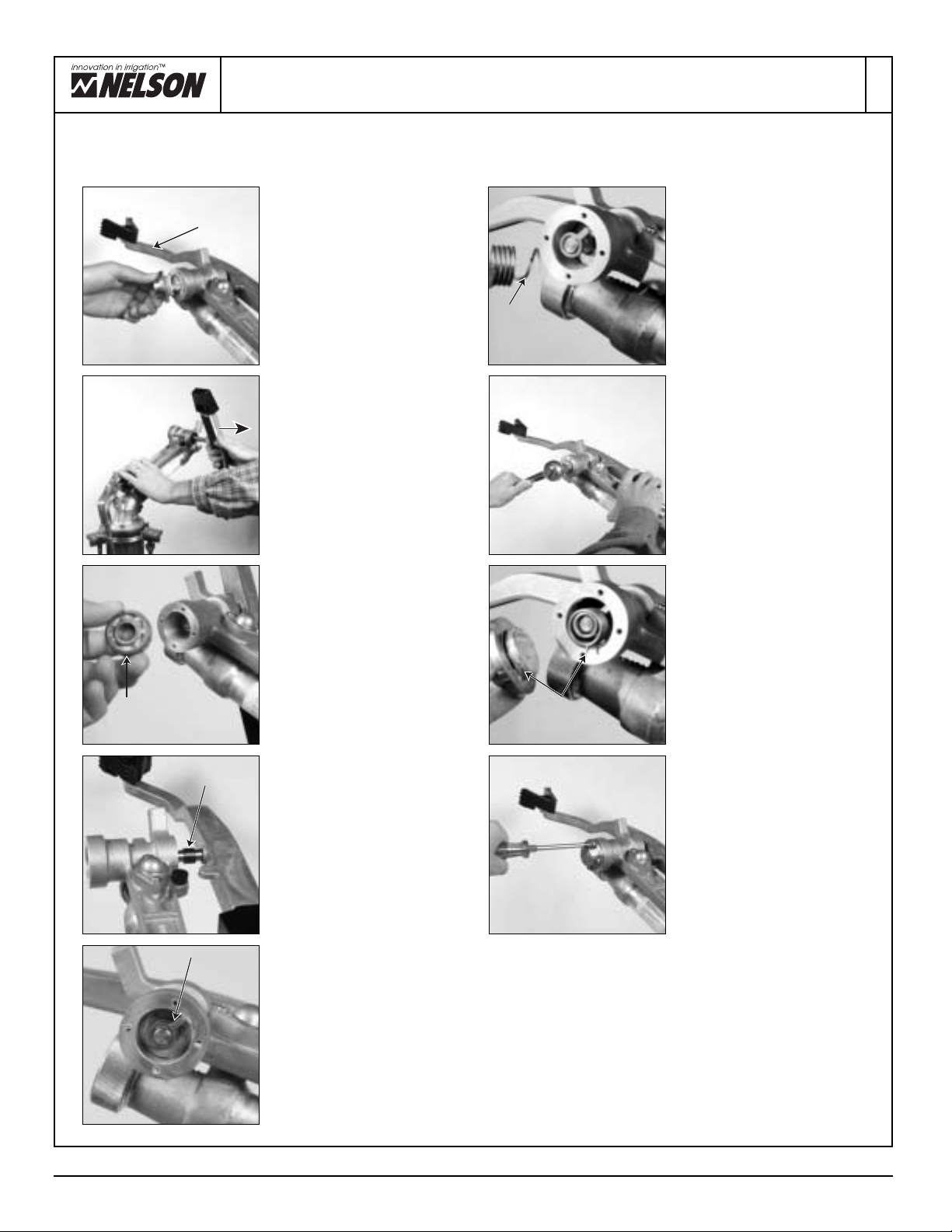
DISASSEMBLY (LOWER UNIT)
STEP 4
Remo e #7763 Co er from shaft.
Remo e #6997 Seal from co er.
Remo e #6996 Brake Ring and
#7009 Dust Seal from shaft.
Inspect all parts for wear and
replace as required.
REASSEMBLY (LOWER UNIT)
STEP 5
Assemble #7009 Dust Seal onto
#7031 Shaft Assembly. Slide
#6996 Brake Ring onto shaft.
Locate the four studs of the brake
ring in the center holes between
the smaller threaded holes.
STEP 9
Install 7007-001 O-Ring into
Spacer and mount onto assembly.
SEE BACK PAGE FOR PARTS LIST
STEP
Remo e the #6998 Seal. To
remo e the two #6559 Bearings
use a hammer and three blocks
of wood. Lightly tap uniformly
around inner race of bearing until
remo ed. Bearings are remo ed
from opposite sides of the #8472
Housing.
STEP 8
Install #6999 O-Ring in #7003
Retainer an assemble retainer on
shaft. Using metho escribe in
isassembly (Lower Unit) instructions
Step 12, secure bearing shaft from
rotating. Torque Retainer to 95-110
ft. lbs. Apply a light coating of #9673
Silicone Grease to O.D. of Retainer.
Assemble #6998 Lip Seal. Orient
with lip si e out. Metric Torque =
129-149 NM or 13-15 MKG.
STEP 2
The #10083 Retainer Assembly is
remo ed by using spanner wrench.
To hold the #7031 Shaft Assembly
from rotating insert two 5/16-18
bolts (#6635) into shaft top.
Clamp bolt heads into a ise
securely. Remo e retainer and
#8472 Housing from bearing
shaft.
STEP 7
Assemble #6566 Gasket. Press
on #8472 Housing. Fully pack
housing with #6143 Lubricant.
Assemble #6559 Bearing into
housing.
STEP 1
Remo e three #7990 or #7991
bolts from flange. Separate
#8472 housing from #10087
Spacer Assembly. Remo e
#7007 O-Ring from #10087
Spacer Assembly.
STEP 6
Place #6997 Lip Seal into #7763 cover
as shown with Nelson name toward
ball bearing. Pack #6559 earing
with #6143 lubricant or equivalent.
(See Notes on Lubrication on the
front cover.) Press bearing into
#6858 Cover. Slide cover assembly
onto bearing shaft. CAUTION: Do
not get grease on brake surfaces.
To clean plastic brake, use soap and
water (solvents may damage plastic).
Clean #6858 cover with acetone.
6/04
#8472
#10083
#7763
#6997
#6996
#7031
#6996
or
#9492
#7009
#6997
#6559
#6998 #10083
#7007-001
#10087 Spacer Assembly
#7991
or 7990
#10087
#7007
(Bronze Model #9492)
STEP 10
Assemble #8967 O-Ring into the
Flange Adapter. Mount Flange
Adapter using required Bolts.
Torque Bolts to 130-150 inch
pounds.
O-Ring
#8967

LOWER BEARING ASSEMBLY PARTS LIST
Nelson Irrigation Corporation 848 Airport Rd. Walla Walla, WA 99362-2271 U A Tel: 509.525.7660 Fax: 509.525.7907 in[email protected] Web site: www.nelsonirrigation.com
6/04
BEARING ASSEMBLY HD 100
part number description qty.
6559 Bearing, Ball, 50 x 80 x 16mm 2
6566 Gasket, Housing - HD100 2
6635 Screw, .3125 -18 x .688 Hex Hd Cap 4
6996 Ring, Brake - HD100 1
6997 Seal, Upper - HD100 1
6998 Seal, Center - HD100 1
6999 O-Ring, -224 1
7004 Spring, Brake - HD100 8
7006 Screw, .312-18 x 3.50 Hex Skt Hd Cap 3
7007-001 O-Ring, -331 Special, w/ grease & graphite 1
7009 Seal, Dust - HD100 1
7031 Shaft Assembly - HD100 1
7763 Co er, Full Circle - HD100 1
7990 Screw, .312-18 x 4.25 Hex Hd Cap 3
7991 Screw, .312-18 x 4 Hex Skt Hd Cap 3
8472 Housing - HD100 1
8967 O-Ring -231, Special 1
10083 Retainer Assembly - HD100 1
10086 Flange Assembly, Nelson 1
10087 Spacer Assembly - HD100 1
10088-001 Flange Assembly, 2 FNPT 1
10088-002 Flange Assembly, 2.5 FNPT 1
10088-003 Flange Assembly, 2 FBSP 1
10088-006 Flange Assembly, 1.5 FNPT 1
10088-007 Flange Assembly, 1.5 FBSP 1
10094 Flange Assembly, Metric 1
10137-001 Flange Assembly, ANSI/DIN 1
10342 O-Ring, -225 1
MOUNTING HARDWARE
part number description qty.
7000 Gasket, Flange 1
7039 Screw, .312-18 x .75 Hex Skt Hd Cap 6
10149 Gasket, Metric Flange 1
Other Nelson Irrigation System manuals

Nelson
Nelson BIG GUN 75 Series User manual

Nelson
Nelson ROTATOR R2000WF User manual

Nelson
Nelson R75 Installation guide

Nelson
Nelson PRO 6000 Guide

Nelson
Nelson R55 User manual

Nelson
Nelson 3000 Series User manual

Nelson
Nelson Traveling Sprinkler User manual

Nelson
Nelson SRNV100 User manual

Nelson
Nelson F44AAB User manual

Nelson
Nelson R55VT User manual