TFP342_EN Page 3 of 6
the need for in-rack sprinkler protec-
tion) of cartoned or uncartoned unex-
panded Group A or B plastics, or, car-
toned expanded Group A or B plastics,
with:
•
a storage height of up to 20 feet (6,1
m);
•
a maximum ceiling height of 27 feet
(8,2 m);
•
a minimum deflector to top of stor-
age clearance of 18 inches (457
mm);
•
a minimum design density of 0.60
gpm/ft2(24,4 mm/min);
•
a minimum residual (flowing) pres-
sure of 10 psi (0,7 bar);
•
a minimum design area of 2000 ft2
(186 m2) for wet systems or 2600 ft2
(242 m2) for dry pipe systems
FM Approval
Requirements
The 11.2 K-factor, Model ELO-231B
(TY5151, TY5251 & TY5851) Sprin-
klers are to be installed in accordance
with the applicable “control mode den-
sity/area” guidelines provided by Fac-
tory Mutual. (FM guidelines may differ
from UL and C-UL Listing criteria.)
Operation
The glass bulb contains a fluid that
expands when exposed to heat. When
the rated temperature is reached, the
fluid expands sufficiently to shatter the
glass bulb, allowing the sprinkler to
activate and water to flow.
Installation
The Series ELO-231B Sprinklers must
be installed in accordance with the fol-
lowing instructions:
NOTES
Do not install any bulb type sprinkler if
the bulb is cracked or there is a loss of
liquid from the bulb. With the sprinkler
held horizontally, a small air bubble
should be present. The diameter of the
air bubble is approximately 1/16 inch
(1,6 mm) for the 155°F/68°C to 3/32
inch (2,4 mm) for the 286°F/141°C
temperature ratings.
A leak tight 3/4 inch NPT sprinkler joint
should be obtained with a torque of 10
to 20 ft.lbs. (13,4 to 26,8 Nm). A maxi-
mum of 30 ft.lbs. (40,7 Nm) of torque
is to be used to install sprinklers with
3/4 NPT connections. A leak tight 1/2
inch NPT sprinkler joint should be ob-
tained with a torque of 7 to 14 ft.lbs.
(9,5 to 19,0 Nm). A maximum of 21 ft.
lbs. (28,5 Nm) of torque may be used
to install sprinklers with 1/2 NPT con-
nections. Higher levels of torque may
distort the sprinkler inlet and cause
leakage or impairment of the sprinkler.
Do not attempt to make-up for insuffi-
cient adjustment in the escutcheon
plate by under- or over-tightening the
sprinkler. Readjust the position of the
sprinkler fitting to suit.
The Series ELO-231B Upright and
Pendent Sprinklers must be installed
in accordance with the following in-
structions.
Step 1. Pendent sprinklers are to be
installed in the pendent position, and
upright sprinklers are to be installed in
the upright position.
Step 2. With pipe thread sealant ap-
plied to the pipe threads, hand tighten
the sprinkler into the sprinkler fitting.
Step 3. Tighten the sprinkler into the
sprinkler fitting using only the W-Type
3 Sprinkler Wrench (Ref. Figure 2),
except that an 8 or 10 inch adjustable
Crescent wrench is to be used for wax
coated sprinklers. With reference to
TFP342 Page 3 of 6
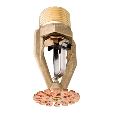
FIGURE 1
11.2 K-FACTOR SERIES ELO-231B
UPRIGHT - 3/4" NPT (TY5151), UPRIGHT - 1/2" NPT (TY5851), AND PENDENT - 3/4" NPT (TY5251) SPRINKLERS
"FITTIN
IDE"
FITTING
TOWARDS SPRINKLER
RECESS
WRENCH
(END "A")
FIGURE 2
W-TYPE 3 SPRINKLER
WRENCH
PENDENT
TY5251
1/2" (12,7 mm)
NOMINAL MAKE-IN
7/16" (11,1 mm)
NOMINAL MAKE-IN
Temperature rating is indicated on deflector.
Pipe thread connections per ISO 7/1 can be provided on
TYP.
2-13/16"
(71,4 mm)
UPRIGHT
TY5851
special request.
**
*
UPRIGHT
TY5151
NOMINAL MAKE-IN
1/2" (12,7 mm)
**
NPT
1/2"
WRENCH
FLATS
**
RELIEF
THREAD
3/4"
NPT
Deflector
Screw
Compression
Bulb
Components:
Seal
Cap
Frame
-
4
2
6
5
4
3
CROSS
SECTION
6
5
-
-
NPT
**
3/4" 1
2
3
1
-
-
-
*
Assembly
FIGURE 1
K160 SERIES ELO-231B UPRIGHT - 3/4” NPT (TY5151), UPRIGHT - 1/2” NPT (TY5851), AND PENDENT - 3/4” NPT
(TY5251) SPRINKLERS
UPRIGHT
TY5851
WRENCH
FLATS
71 mm
(2-13/16”)
TYP.
NOMINAL MAKE-IN
12,5 mm (1/2”)
Components
1 - Frame
2 - Sealing
Assembly
3 - Cap
4 - Bulb
5 - Compression
Screw
6 - Deector *
* Temperature rating is indicated on deector.
**Pipe thread connections per ISO 7/1 can be
provided on special request.
Operation
The glass bulb contains a uid that expands
when exposed to heat.When the rated tem-
perature is reached, the uid expands su-
ciently to shatter the glass bulb, activating
the sprinkler and allowing water to ow.
Installation
The Series ELO-231B Sprinklers must be
installed in accordance with the following
instructions:
NOTES
Do not install any bulb type sprinkler if the
bulb is cracked or there is a loss of liquid from
the bulb. With the sprinkler held horizontally,
a small air bubble should be present. The di-
ameter of the air bubble is approximately 1,5
mm (1/16”) for the 57°C (135°F) to 2,5 mm
(3/32”) for the 141°C (286°F) temperature rat-
ings.
A leak tight 3/4” NPT sprinkler joint should be
obtained with a torque of 13 to 27 Nm (10 to
20 ft.lbs.). A maximum of 41 Nm (30 ft.lbs.) of
torque is to be used to install sprinklers with
3/4 NPT connections. A leak tight 1/2” NPT
sprinkler joint should be obtained with a
torque of 9,5 to 19 Nm (7 to 14 ft.lbs.). A maxi-
mum of 29 Nm (21 ft. lbs.) of torque may be
used to install sprinklers with 1/2 NPT connec-
tions. Higher levels of torque may distort the
sprinkler inlet and cause leakage or impair-
ment of the sprinkler.
sprinkler, loosen the wrench jaws before
removing the wrench.
After installation, the sprinkler wrench ats
and frame arms must be inspected and the
wax coating retouched (repaired) whenev-
er the coating has been damaged and bare
metal is exposed. The wax coating on the
wrench ats can be retouched by gently
applying a heated 1/8 inch diameter (M3)
steel rod to the areas of wax that have been
damaged, to smooth it back over areas
where bare metal is exposed.
NOTES
Only retouching of the wax coating applied to
the wrench ats and frame arms is permitted,
and the retouching is to be performed only at
the time of the initial sprinkler installation.
The steel rod should be heated only to the
point at which it can begin to melt the wax,
and appropriate precautions need to be tak-
UPRIGHT
TY5151
PENDENT
TY5251
CROSS
SECTION
NOMINAL MAKE-IN
12,5 mm (1/2”)
NOMINAL MAKE-IN
11,1 mm (7/16”)
THREAD
RELIEF
the need for in-rack sprinkler protec-
tion) of cartoned or uncartoned unex-
panded Group A or B plastics, or, car-
toned expanded Group A or B plastics,
with:
•
a storage height of up to 20 feet (6,1
m);
•
a maximum ceiling height of 27 feet
(8,2 m);
•
a minimum deflector to top of stor-
age clearance of 18 inches (457
mm);
•
a minimum design density of 0.60
gpm/ft2(24,4 mm/min);
•
a minimum residual (flowing) pres-
sure of 10 psi (0,7 bar);
•
a minimum design area of 2000 ft2
(186 m2) for wet systems or 2600 ft2
(242 m2) for dry pipe systems
FM Approval
Requirements
The 11.2 K-factor, Model ELO-231B
(TY5151, TY5251 & TY5851) Sprin-
klers are to be installed in accordance
with the applicable “control mode den-
sity/area” guidelines provided by Fac-
tory Mutual. (FM guidelines may differ
from UL and C-UL Listing criteria.)
Operation
The glass bulb contains a fluid that
expands when exposed to heat. When
the rated temperature is reached, the
fluid expands sufficiently to shatter the
glass bulb, allowing the sprinkler to
activate and water to flow.
Installation
The Series ELO-231B Sprinklers must
be installed in accordance with the fol-
lowing instructions:
NOTES
Do not install any bulb type sprinkler if
the bulb is cracked or there is a loss of
liquid from the bulb. With the sprinkler
held horizontally, a small air bubble
should be present. The diameter of the
air bubble is approximately 1/16 inch
(1,6 mm) for the 155°F/68°C to 3/32
inch (2,4 mm) for the 286°F/141°C
temperature ratings.
A leak tight 3/4 inch NPT sprinkler joint
should be obtained with a torque of 10
to 20 ft.lbs. (13,4 to 26,8 Nm). A maxi-
mum of 30 ft.lbs. (40,7 Nm) of torque
is to be used to install sprinklers with
3/4 NPT connections. A leak tight 1/2
inch NPT sprinkler joint should be ob-
tained with a torque of 7 to 14 ft.lbs.
(9,5 to 19,0 Nm). A maximum of 21 ft.
lbs. (28,5 Nm) of torque may be used
to install sprinklers with 1/2 NPT con-
nections. Higher levels of torque may
distort the sprinkler inlet and cause
leakage or impairment of the sprinkler.
Do not attempt to make-up for insuffi-
cient adjustment in the escutcheon
plate by under- or over-tightening the
sprinkler. Readjust the position of the
sprinkler fitting to suit.
The Series ELO-231B Upright and
Pendent Sprinklers must be installed
in accordance with the following in-
structions.
Step 1. Pendent sprinklers are to be
installed in the pendent position, and
upright sprinklers are to be installed in
the upright position.
Step 2. With pipe thread sealant ap-
plied to the pipe threads, hand tighten
the sprinkler into the sprinkler fitting.
Step 3. Tighten the sprinkler into the
sprinkler fitting using only the W-Type
3 Sprinkler Wrench (Ref. Figure 2),
except that an 8 or 10 inch adjustable
Crescent wrench is to be used for wax
coated sprinklers. With reference to
TFP342 Page 3 of 6
FIGURE 1
11.2 K-FACTOR SERIES ELO-231B
UPRIGHT - 3/4" NPT (TY5151), UPRIGHT - 1/2" NPT (TY5851), AND PENDENT - 3/4" NPT (TY5251) SPRINKLERS
"FITTIN
IDE"
FITTING
TOWARDS SPRINKLER
RECESS
WRENCH
(END "A")
FIGURE 2
W-TYPE 3 SPRINKLER
WRENCH
PENDENT
TY5251
1/2" (12,7 mm)
NOMINAL MAKE-IN
7/16" (11,1 mm)
NOMINAL MAKE-IN
Temperature rating is indicated on deflector.
Pipe thread connections per ISO 7/1 can be provided on
TYP.
2-13/16"
(71,4 mm)
UPRIGHT
TY5851
special request.
**
*
UPRIGHT
TY5151
NOMINAL MAKE-IN
1/2" (12,7 mm)
**
NPT
1/2"
WRENCH
FLATS
**
RELIEF
THREAD
3/4"
NPT
Deflector
Screw
Compression
Bulb
Components:
Seal
Cap
Frame
-
4
2
6
5
4
3
CROSS
SECTION
6
5
-
-
NPT
**
3/4" 1
2
3
1
-
-
-
*
Assembly
“FITTING SIDE”
TOWARDS SPRINKLER
FITTING
WRENCH
RECESS
(END “A”)
FIGURE 2
W-TYPE 3 SPRINKLER
WRENCH
Do not attempt to make-up for insucient
adjustment in the escutcheon plate by under-
or over-tightening the sprinkler. Readjust the
position of the sprinkler tting to suit.
The Series ELO-231B Upright and Pen-
dent Sprinklers must be installed in ac-
cordance with the following instructions.
Step 1. Pendent sprinklers are to be in-
stalled in the pendent position, and upright
sprinklers are to be installed in the upright
position.
Step 2. With pipe thread sealant applied to
the pipe threads, hand tighten the sprinkler
into the sprinkler tting.
Step 3. Tighten the sprinkler into the sprin-
kler tting using only the W-Type 3 Sprin-
kler Wrench (Ref. Figure 2), except that a
200 or 250 mm (8 or 10”) adjustable Cres-
cent wrench is to be used for wax coated
sprinklers. With reference to Figure 1, the
W-Type 3 Sprinkler Wrench or the adjust-
able Crescent wrench, as applicable is to be
applied to the wrench ats.
When installing wax coated sprinklers with
the adjustable Crescent wrench, additional
care needs to be exercised to prevent dam-
age to the wax coating on the sprinkler
wrench ats or frame arms and, conse-
quently, exposure of bare metal to the cor-
rosive environment. The jaws of the wrench
should be opened suciently wide to pass
over the wrench ats without damaging
the wax coating. Before wrench tightening
the sprinkler, the jaws of the wrench are to
be adjusted to just contact the sprinkler
wrench ats. After wrench tightening the
