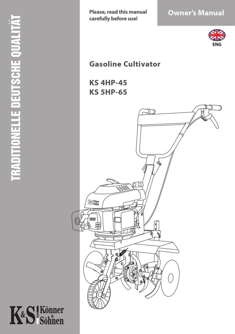
Könner & Söhnen KS 7HP-850A User manual

GASOLINE TILLERS
KS 7HP-850A
KS 7HP-950A
KS 7HP-950S
KS 7HP-1050G
KS 9HP-1350G-3
Please, read this manual
before use!
Instruction
ENG

1
TABLE OF CONTENTS
1. Introduction 2
2. Tiller overview 2
3. Safety symbols description 3
4. Overview and components of the tiller 4-7
5. Specications 8
6. Safety technique 9
7. Composition 11
8. Collecting the cultivator 12-17
9. Operation instruction 18-20
10. Maintenance 21-24
11. Troubleshooting 25
12. Transportation 26
13. Storage 26
14. Waste 26
SYMBOL EXPLANATIONS:
KS Könner & Söhnen production
850, 950, 1050, 1350 Model name
7HP, 9HP power of the cultivator, HP
Read this manual carefully. Pay special attention to information starting with
characters / words
Failure to observe the recommendation marked with this sign may result in
serious injury or death to the operator or third parties.
Useful information on using the machine
! !
ATTENTION - DANGER
! !
IMPORTANTLY!

2
Tiller is equipped with mechanic gearbox, which is simple in maintenance and
passes the biggest torque of the engine;
- Chain transmission which is located in solid sturdy cast iron chassis;
- Reverse function to increase maneuverability and usability;
- Easiness in work with the toughest soil pieces and breasts due to forged blades;
- Easy to adjust operator panel height;
- Transportation wheel makes it easy to move the tiller;
- Two forward gears;
- Models KS 7HP-950S and KS 7HP-1050G come with tubeless wheels, with
KS 7HP-1350G-3 coming with pneumatic wheels that facilitate transportation
of the device;
- Models KS 7HP-850A and KS 7HP-950A come with casters;
- Package list includes a wheel, which simplies device and its cargo
transportation .You can buy a wide range of hinged equipment to your tiller that
will make it the most reliable assistant in your garden.
1. PREFACE
We are grateful to you for your purchase of ТМ Könner & Söhnen series
gasoline tiller.This manual contains safe working recommendations, operation
and adjustment description of these tillers and maintenance instructions.
All data, specied in this operation manual is the most up to date for the
moment of its publishing. At the end of this manual, you may nd contact
information which you are free to use in case of any issues occurrence.
We care about the environment, therefore,
we consider it expedient to save paper and
leave in print a short description of the most
important sections.
IMPORTANT!
! !
Manufacturer reserves the right to make alterations into the tillers, which may
not be reected in this manual. Pictures and photos of the product may vary from
its actual appearance.
More information and contacts can be found on the website: www.ks-power.de/en
2. TILLER OVERVIEW
All Könner & Söhnen tillers are equipped with the most powerful OHV
engines of the last generation with such features:
- Increased lifespan;
- Low fuel consumption;
- High power with the low weight;
- Low noise level in comparison to similar engines.

3
3. SAFETY SYMBOLS DESCRIPTION
Engine power
Rated power of tiller
Engine model
Forward speed
Tilling width
Max. tilling depth
Weight
Year of issue
Fuel warnings
Do not touch! The generator
damper becomes
hot during operation.
Speed regulation mark
Noise level is indicated.The noise
level varies with the model.
For more information. Indicates the required oil
level in the crankcase
Oil
recommendations
Crankcase volume
(varies from model
to model)
a.Warning! Important information!
b. Caution! Hot surface!
c. It is prohibited to stay in a woking area of tiller.
d. It is dangerous to touch tiller rotating blades.
e. Observe re safety regulations, do not
operate the generator near open ame!
f. Read this owner’s manual carefully before
operating the device.
g. Keep your legs away from the rotating cutters.
h. Other people should keep a distance
from the operating device.
b c d
f g h
a
e
Position of the air valve (to start position
«Closed» in the direction of the arrow)
Fuel valve (change position to «Open» in
the direction of the arrow)
Transmission
(conguration depends
from the generator model)
Reverse gear
Clutch
Clutch handle position
Operating position
OFF position
(The appearance may vary depending on the
rotary cultivator model )
MAX- MIN

4
4.OVERVIEW AND COMPONENTS
OF THE TILLER
KS 7HP-850A
1.Wing
2.Powerful engine
3.Panel Operator
4.Engine speed control
5.Clutch handle
6. Operator Panel Lock
7. Gear housing
8. Transport wheels
9. Blade (24 pcs)
8
Fig. 1
3
1.Silencer with a protective grille
2.Air lter
3.Fuel tank
4.Fuel tank cap
5.Manual starter
4
12
5
3
4
5
6
7
1
2

5
OVERVIEW AND COMPONENTS OF TILLERS
KS 7HP-950A, KS 7HP-950S
1.Transport wheel for the model
KS 7HP-950A
(support leg for the model
KS 7HP-950S)
2. Engine
3.Steering column
4.Operator panel position adjustment
lever about 360 ° (for the model
KS 7HP-950S)
5.Operator panel
6.Engine speed control
7.On / o switch
8. Clutch handle
9.Tool case (for the model
KS 7HP-950S)
10. Gear lever
11. Reinforced share
12.Gear housing
13. Wing
14. Blade for the KS 7HP-950A -24 pcs ;
and KS 7HP-950S – 32 pcs.
15. Pneumatic wheels
(only for model KS 7HP-950S)
Fig. 2
15
1
2
6
10
3
13
14
7
5
11
1. Air lter
2. Silencer with a protective grille
3. Fuel tank
4. Fuel tank cap
5. Oil ller cap
6. Oil drain screw
7. Switch
8. Manual starter
9. Fuel valve
10. Air damper
123
4
5
6
10
9
8
7
9
48
12

6
1. Air lter
2. Silencer with a protective grille
3. Fuel tank
4. Fuel tank cap
5. Oil ller cap
6. Oil drain screw
7. Switch
8. Manual starter
9. Fuel valve
10. Air damper
123
4
5
6
10 5
9
8
7
1. Transport handle
2. Engine
3. Gear lever
4. Steering column
5. On / o switch
6. Adjusting the engine speed
7. Clutch handle
8. Reverse gear handle
9. Tool case
10. Operator panel
11. Operator panel adjustment lever
12. Reinforced share
13. Wings
14. Pneumatic wheels
15. Blade (32 pcs)
16. Support leg
OVERVIEW AND COMPONENTS
OF THE TILLER
KS 7HP-1050G
15
Fig. 3
3
11
13
4
10
14
5
2
1
7
16
6
8
9
12

7
GENERAL APPEARANCE OF THETILLER
KS 9HP-1350G-3
1. Transport handle
2. Engine
3. Gear lever
4. Steering column
5. On / o switch
6. Adjusting the engine speed
7. Clutch handle
8. Tool case
9. Control panel
10. Operator panel adjustment lever
11. Reinforced share
12. Wings
13. Blads
14. Support leg
Fig.4
3
8
13
1. Air lter
2. Silencer with a protective grille
3. Fuel tank
4. Fuel tank cap
5. Oil ller cap
6. Oil drain screw
7. Switch
8. Manual starter
9. Fuel valve
10. Air damper
123
4
5
6
10 5
9
8
7
1
2
4
9
14
56
7
10
12
11

8
Tiller KS 7HP-850A KS 7HP-950A KS 7HP-950S
Engine model KS 240 KS 240 KS 240
Nominal power, kW 7,0 7,0 7,0
Engine capacity, сm3 212 212 212
Engine type Gasoline
Tilling width, cm ≤ 77 ≤ 105 ≤ 105
Tilling depth, cm ≤ 31 ≤ 31 ≤ 31
Fuel tank volume, l 3,6 3,6 3,6
Transmission system belt-driven
Forward speed 1 +2 +1 0 -1
Reverse - + +
Adjustable handles - vertical vertical/horizontal
Noise level Lpa /Lwa, dB 77/99 74/99 74/99
Gross dimensions (L*W*H), mm 590*380*750 845*460*660 845*460*660
Net weight, kg 54 75 87
Gross weight, kg 59 81 93
5.SPECIFICATIONS
Tiller KS 7HP-1050G KS 9HP-1350G-3
Engine model KS 240 KS 290
Max power, hp 7,0 9,0
Engine capacity, сm3 212 269
Engine type Gasoline
Working width, сm ≤ 103 ≤ 125
Working depth, cm ≤ 35 ≤ 35
Fuel tank capacity, l 3,6 6,0
System transmisji Сonical
Drive type direct drive with gearbox
Forward speed +2 +1 0 -1 +3 +2 +1 0 -1
Reverse + +
Adjustable handles horizontally
Noise level Lpa /Lwa, dB 74/99 74/99
Gross dimensions (L*W*H), mm 580*400*740 1380*650*970
Net weight, kg 75 102
Gross weight, kg 82 110

9
6.SAFETY TECHNIQUE
Before operating the cultivator, please read carefully the operating instructions. Do
not allow other people and children to use the device. Do not use the appliance in
close proximity to the work area of adults, children and animals - the responsibility
for accidents and property is borne by the cultivator user. The Könner & Söhnen
motor cultivator meets the safety requirements of the current European standards.
In no case do any changes to the design of the appliance.
WARNING THESE REQUIREMENTS FOR WORKING WITH THE CULTIVATOR:
1. Read this manual before starting to work with equipment. Keep it for the
future, follow the recommendations contained in it, as this will help prevent
injury and damage to the device.
2. Familiarize yourself with the cultivator management and its functions. In the
event of unforeseen circumstances, the operator must know how to stop the
cultivator’s working parts and its engine.
3.The operator of the device must be in good physical and mental state, must be
able to quickly make decisions if necessary. It is forbidden to work with a
cultivator after drinking alcohol, drugs or taking medications that can slow down
the reaction.
4.The cultivator is intended for use with soil during sowing, as well as for the care
and treatment of plants.The use of a cultivator for other purposes is forbidden.
WORKING WITH THE CULTIVATOR
The device must be turned on according to the instructions in this manual. Ensure
that the cultivator is safely spaced from the legs. Do not place your feet or hands
on rotating items or underneath them. In order to lift the device, two people
have to take up the handle and the cultivator shafts. Wear special gloves for
protection of hands and protective shoes, do not work with a cultivator in an
open shoe.
BE CAREFUL!
- Keep clean engine and exhaust pipe in order to avoid burning. Carefully check
them for the absence of leaves, grass and leaks of oil or fuel.
- Be careful with the rotating parts. Do not touch the mill when rotated.
Drain the waste oil into a tight container. Allow waste oil to the point
of recovery of waste oil.
! !
ATTENTION - DANGEROUS

10
OPERATION OF THE DEVICE AT THE GOOD LOCATION
1. Keep track of the correct location of the appliance on the slopes. The angle
of inclination of 10% corresponds to 10 cm, a rise of 100 cm to the horizontal
plane. Do not apply soil plowing on steeper slopes, in order not to lose control
of the device.
2. When working on slopes or hilly terrain, reinstall all mills.
3. The person working with the cultivator is prohibited from standing below
the device in order to avoid getting into the working cultivator in case of loss
of control over it.
4. It is prohibited to operate the device across the slope. Only move forward, do
not pull the cultivator back and forth.
5. Be careful when changing the direction of the cultivator.
6. Reduce speed on rocky soil.
7. Work with the cultivator should occur only in the pace of the step, as there is a
risk of stumbling, slipping, etc. when moving fast.
8. To adjust the depth of the device, change the force of pressing on the handle,
pressing the coulter in the ground more or less.
9. Do not turn engine, do not change its main position!
STORAGE AND USE OF GASOLINE
Petrol is extremely toxic and combustible, so observe the following rules for its
storage and use:
1. Only store fuel in hermetically sealed containers specially designed for this
purpose. Hold the canister with gasoline in the cool. Dark place as far away from
sparks and open ames.
2. During operation of the engine, the cultivator allocates exhaust gases that can
cause poisoning. Do not use the device in closed, badly ventilated areas.
3. Fill the cultivator in the open air before starting the engine. Do not squeeze
the gas tank cover and do not ll the fuel if the cultivator is still hot after work.
4. Leave the place to expand the fuel after refueling. Pour fuel to the edge of the
lling pipe (about 4 cm from the top of the tank). Do not ll the tank completely.
5. If there is too much gasoline, thoroughly wipe excess from the surface if it is
lled with fuel. In no case do not start the engine until the surface is cleaned up
and until steam of gasoline evaporates.
6. Always close the gas tank cover tight.
7. To empty the fuel tank, start the cultivator engine out of the room until
complete fuel production.
8. The cultivator should only be transported empty. A fuel tank and a closed fuel
tap.
9. Wait until the device cools down before putting it on storage.
10. For safety reasons, do not leave the fuel tank in the gas tank in the enclosed
area. Gasoline vapors can come in contact with sparks or open ame, which may
lead to vaporization.
11. Regularly check the device for damage and imperfection of the fuel line, tank
and fuel tank plugs, as well as damage to the muer and protective plates. In
time, replace the parts if necessary.
MAINTENANCE AND REPAIR
When using a cultivator on slopes, lifting must not exceed 10% (5.7 °). Operation
of the device is possible only in daylight or good articial lighting.To avoid injury
and damage.

11
Use only original spare parts, replace worn or damaged parts on time, tighten all
bolts, screws and nuts all the way.
Follow the maintenance instructions listed in the instruction manual yourself.
Before starting work on the device, disconnect the plug of the spark plug
wire. Works that are not foreseen for self-fulllment must be performed at an
authorized Könner & Söhnen Service Center. The addresses of the service centers
can be found on our ocial website www.//ks-power.de/en/
7. COMPOSITION
1. Cultivator 1 pc.
2. Number of blades for mills:
KS 7HP-850A 24 pc.
KS 7HP-950А 24 pc.
KS 7HP-950S 32 pc.
KS 7HP-1050G 32 pc.
KS 9HP-1350G-3 40 pc.
3. Reinforced share 1 pc.
4. Support leg
(except model KS 7HP-950S, KS 7HP-1050G, KS 9HP-1350G-3) 1 pc.
Transport wheel
(except model KS 7HP-850A, KS 7HP-950A ) 1 pc.
5.Parking support bracket
(except model KS 7HP-850A, KS 7HP-950A, KS 7HP-950S) 1 pc.
6. Console 1 pc.
7. Side protectors 2 pc.
8. Control panel 1 pc.
9.Pneumatic wheels
(except model KS 7HP-950S, KS 7HP-1050G, KS 9HP-1350G-3) 2 pc.
10. A set of fasteners and tools 1 pc.
11. Operating Instructions 1 pc.
12. Packing 1 pc.
The fuel contaminates the earth and groundwater. Do not allow gas to
run out of the tank!
! !
ATTENTION - DANGER

12
COULTER
To adjust the depth of the
plow in the cultivator there
is a coulter. It is regulated
by moving it up and down
with an elongated clamp.
The more depth the coulter
gets, the greater the depth of
processing the earth.
Secure the coil holder (2) with
the vertical pin (1), insert the coil (4) into the bracket, adjust the height using a bolt (3).
34
1
1. Soshnik
2. Bolt
3. Mounting bracket
4.Vertical nger
2
Fig. 5
8. COLLECTING THE CULTIVATOR
Fig. 8 Fig. 9
ASSEMBLY OF THE TRANSPORT WHEEL
To move the cultivator, it is equipped with a forward transport wheel. Attach the
transport wheel to the cultivator frame using bolts (Fig. 8)
To move, lower the wheel down and x it with the mounting pin. Raise the steering
wheel so that the cultivator is easy to roll on the ground. Before starting ground
treatment.Turn the wheel in the raised position and lock it with a pin.
Fig. 7
Fig. 6
Transportation
Cultivation
Spinnette and nger
MOUNTING THE RUBBER WHEELS
Attach the wheels to the cultivator by inserting the fasteners into the corresponding
axle holes.

13
CUTTING CUTTERS ASSEMBLING.
The product comes with the blades.
The number of blades (24 pcs, 32 pcs, 40 pcs) varies with the cultivator model.
There are two mounting options:
1.Three sections with four knives (82 cm width); 2. Four sections with four knives
(115 cm width).
To increase the trim width, kit also includes an elongated midsole.
Fig. 10
Fig. 11
Fig. 12
When attaching the blades, always pay attention to the position of the cutting
edge of the blades. It should face the direction of travel of the cultivator. Cutters are
secured with bolts.The disk is connected to the main structure using a bolt.

14
For the KS 7HP-950S, attach the operator’s panel to the steering column using
the xing bolt as shown in Fig. 15.
Fig. 15
Fig. 15b
Panel lock
operator (lever)
For KS 7HP-950G, KS 7HP-1050G, and KS 13HP-1350G-3, rst assemble the
steering column and then connect the operator’s panel as shown in Fig. 15b.
PANEL OPERATOWA
For model KS 7HP-850A, rst attach the operator’s panel to the steering column
using the xing bolts, then attach the engine speed control, as shown in gures
15, 15d.
Fig. 15а
Fig. 15
Fig. 15с

15
Panel lock
operator (lever)
TRANSMISSION COVER
Attach the transmission cover to the cultivator by inserting the fasteners into the
corresponding holes.
Fig. 17
Fig. 16
FENDERS
Attach the fenders to the cultivator frame by inserting the fasteners into the
corresponding holes.
Fig. 19
Fig. 18
SUPPORT FOOT
Attach the cultivator’s support foot to the bracket by inserting the fasteners into
the corresponding holes.
Fig. 21
Fig. 20

16
The cultivator is supplied without oil and fuel.
Before rst start-up, be sure to ll in the oil and refuel the device!
Use a funnel (not supplied) to refuel.
! !
ATTENTION - DANGEROUS!
Drain the waste oil into a tight container. Allow waste oil to the point
of recovery of waste oil.
! !
ATTENTION - DANGEROUS!
ENGINE SPEED CONTROL AND CLUTCH CABLES
Engine speed adjustment is carried out with the help of a gas handle (1).
The start of the cultivator is carried out with the clutch handle (2).
1. Gas handle
2. Clutch handle
Fig 23
Fuel tank
Oil ller cap/ oil
dipstick
Fig. 22

17
OPERATOR PANEL POSITION:
1. Loosen the bolt that xes the position of the operator panel.
2. Install the operator panel to the required height.
3. Fasten the panel with a bolt.
SHIFT LEVER.
To work with the lever:
1. Set the lever to the neutral position «0».
2. Move the shift lever to the required speed to the right - «2» or «1».
3. To turn the reverse «-1», move the lever to the left.
(The appearance may vary depending on the rotary cultivator model)
Operator
panel locks
Shift lever
Fig. 24
Fig. 25

18
9. OPERATION INSTRUCTION
During the commissioning:
1. Fill the crankcase with engine oil.
2. Fill the transmission case with
SAE 75W-90, SAE 80W-90 or SAE 85W-90 grade oil
to the level specied for a given model. Be sure to
check the oil level with an oil dipstick, as the device
may contain residual oil after a production check. Do
not exceed the recommended amount of oil!
3. Fill the fuel tank with gasoline.
4. Unscrew the air lter cover (Fig. 11) and ll 50-100 ml of engine oil into the air lter
separator. Package contents may vary. For an engine with a paper lter, there is no
need to ll the separator with engine oil.
USEFUL TIPS
1.To determine the tilling depth, use the coulter at dierent heights.With the coulter
driven deeper into the soil, the cutters also go deep into the soil and the advancement
of the device forward slows down considerably.
2. The cultivator speed is determined by adjusting the engine speed. The cutters go
deep into the soil with the device in the xed position.
3.To speed up the cultivator advancement, adjust the coulter higher to lift the cutters.
4. Immediately release the clutch lever when the cultivator is blocked by foreign
objects. Kill the engine, remove obstacles and check the cultivator for deformation
and damage. Replace damaged parts as necessary.
FUEL AND ENGINE OIL
The tiller needs normal unleaded fuel with 92 octane for proper work. Gasoline
should be fresh, vintage variety. Use a funnel (not supplied) for best device lling.
The tiller also can not run without oil, so ll it before the rst launch. Set the device
on a at horizontal surface, open the tank with oil and pour oil to the minimum mark.
Use the probe to check the oil level. Oil level must be constantly monitored. Do not let
excess of oil and its lack. Information on used motor oil can be found in the technical
characteristics of the tiller.
filter cap
lter element
fill 50-100 ml
of oil
Fig. 26

19
STARTING AND STOPPINGTHE ENGINE
Before starting the engine, make sure the switch is in position I (on). Turn the rotary
engine speed dial to MAX (see picture 27). Damper motor switch to position CHOKE.
Grasp the starter handle and slowly pull it to the emergence of resistance, then sharp
fast motion pull starter all the way. Repeat the operation until the engine starts. After
startingthe engine let the rope to entangle on trigger without throwing the starter
handle. Put the aps in position RUN.
THE THROTTLE ADJUSTMENT
Clutch transmits engine from the engine to the transmission torque. When
youpress the handle grip, rotation turns on and belt movement is transmitted
to the chain transmission. Transport the tiller to plowing land. Start the
engine and turn the required forward speed of the assisted lever gearbox.
After pressing and holding the lever, tiller starts to bury into the ground while
moving forward.
Adjust the height of the depression in the ground with opener.
Fig. 27
Fig. 28
To eliminate the engine turn the switch to O (O.) position.
Starting
grip
Extinguish switch OFF
ON
Throttle
governor
Other manuals for KS 7HP-850A
3
This manual suits for next models
4
Table of contents
Other Könner & Söhnen Tiller manuals

Könner & Söhnen
Könner & Söhnen KS 7HP-950A User manual

Könner & Söhnen
Könner & Söhnen KS 4HP-45 User manual

Könner & Söhnen
Könner & Söhnen KS 7HP-850A User manual

Könner & Söhnen
Könner & Söhnen KS 7HP-850A User manual

Könner & Söhnen
Könner & Söhnen KS 7HP-850A User manual

Könner & Söhnen
Könner & Söhnen KS 7HP-950A User manual

Könner & Söhnen
Könner & Söhnen KS 1000T E User manual