konner-sohnen.com |
COMPOSITION 4
Tiller KS 7HP-1000G KS 7HP-1050G KS 9HP-1350G-3 KS 600RTG
Engine model KS 240 KS 240 KS 290 KS 240
Engine power, HP 7,0 7,0 9,0 7,0
Nominal power, kW 4,0 4,0 6,0 4,0
Engine capacity, сm3212 212 270 212
Engine type gasoline
Tilling width, cm ≤ 109 ≤ 108 ≤ 134 ≤ 58
Tilling depth, cm ≤ 31 ≤ 35 ≤ 35 ≤ 15
Fuel tank volume, l 3,6 3,6 6,0 3,6
Crank case volume, l 0,6 0,6 1,1 0,6
Transmission case volume, l 1,2 1,2 1,5 2
Engine start manual manual manual manual
Drive type direct drive with gearbox
Forward speed +2 +1 0 -1 +2 +1 0 -1 +3 +2 +1 0 -1 +1 0 -1
Blades (sets/psc) 2x4x4 / 32 2x4x4 / 32 2x5x4 / 40 2x2x3 / 12
Reverse ++++
Adjustable handles vertical vertical/horizontal vertical/horizontal vertical
Noise level Lpa (7m)/Lwa, dB 73/98 73/98 73/98 73/98
Dimensions (LxWxH), mm 845x460x660 910х460х690 910х570х750 1170x570x440
Net weight, kg 70 83 94 65
The optimum operating conditions are ambient temperature of 17-25°C, barometric pressure of 0.1 MPa (760 mm Hg),
and relative humidity of 50-60%, Altitude (MAX), ≤ 300 m. Under such ambient conditions, the generator can guarantee
maximum performance in terms of the stated specifications. In case of deviations from the above ambient values (altitude
above sea level, temperature, pressure) the performance of the generator can be different.
1. Tiller – 1 pc.
2. Number of blades for mills:
KS 7HP-850A – 24 pcs.
KS 7HP-950А – 32 pcs.
KS 7HP-950S – 32 pcs.
KS 7HP-1000G – 32 pcs.
KS 7HP-1050G – 32 pcs.
KS 9HP-1350G-3 – 40 pcs.
KS 600RTG - 12 pcs.
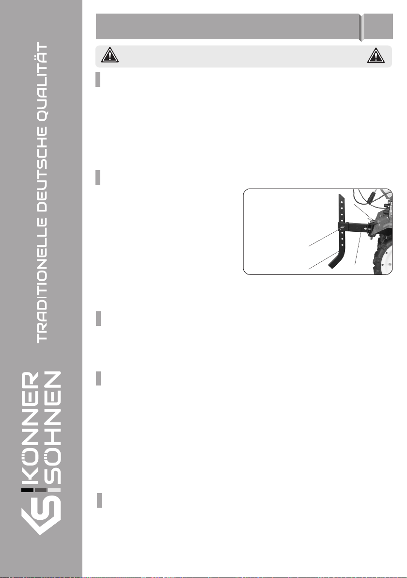
3. Coulter – 1 pc.
4. Support leg
(for models KS 7HP-950S,
KS 7HP-1050G, KS 9HP-1350G-3) – 1 pc.
Transport wheel (for models
KS 7HP-850A, KS 7HP-950A, KS 7HP-1000G) – 1 pc.
5. Gear housing (for models KS 7HP-950A, KS 7HP-950S,
KS 7HP-1050G, KS 7HP-1000G, KS 600RTG) – 1 pc.
6. Console – 1 pc.
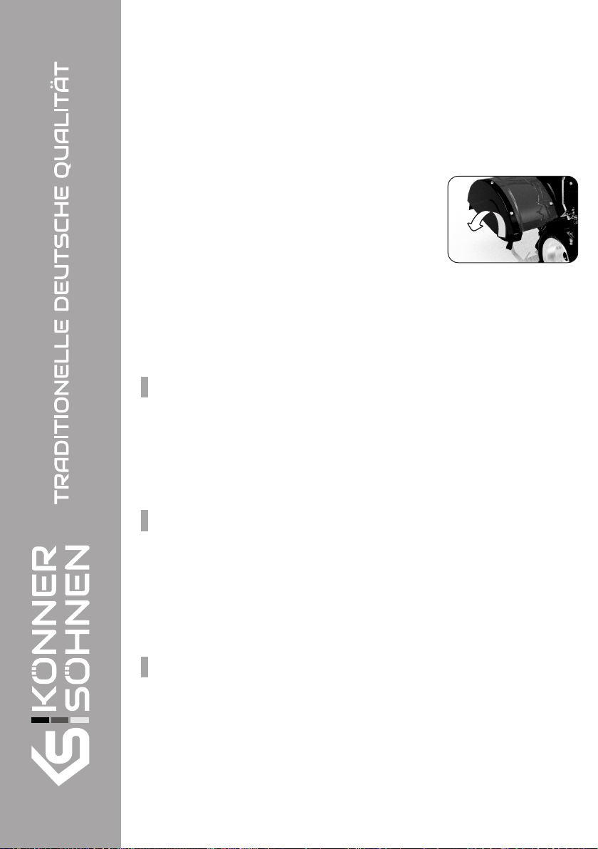
7. Side protectors – 2 pcs.
8. Control panel – 1 pc.
9. Pneumatic wheels (for model КS 7HP-950S,
KS 7HP-1050G, KS 7HP-1000G,
KS 600RTG,
KS 9HP-1350G-3) – 2 pcs.
10. A set of fasteners and tools – 1 pc.
11. Manual – 1 pc.
12. Packing – 1 pc.
13. Reflective stickers for front grille
(for model KS 9HP-1350G-3) – 6 pcs.
konner-sohnen.com |4