7 / 84
1. GENERAL INFORMATION AND
SAFETY INSTRUCTIONS
1.1. About the User Manual
The usage and operation information
given in this manual is prepared to make
sure the vehicle is used in compliance
with its purpose and as desired.
The instructions here contain important
recommendations to perform your oper-
ations safely, completely, and in the most
efficient manner. Complying with these
instructions, warnings and recommenda-
tions will prevent accidents, decrease
down-time & repair costs, and make sure
you use your vehicle safely, reliably and
problem-free.
Please read the operating instructions in
this manual carefully and completely.
The manufacturer is not liable for the
damages and deficiencies caused by the
failure to comply with these instructions.
The instructions herein must be sup-
ported by local laws, rules and regula-
tions. Please comply with these
instructions to prevent accidents and
protect your surroundings and the
environment.
Any usage of transportation that goes
beyond the use in accordance with the
rules will be considered improper use.
Transportation of the following is not
allowed:
•Carrying people and live animals
•Transportations that need to be car-
ried according to special instruc-
tions, e.g., dangerous good
transportations
•Transportation of unsecured goods
•Transportation of materials that are
dangerous due to their properties or
that need to be carried with special
equipment
•Exceeding technically and legally
permissible weights of the axles or
king pin load
•Exceeding of the maximum vehicle
speed
•Exceeding the permissible length,
width and height
•Unapproved parts like tires, acces-
sories, spare parts and etc. by the
manufacturer
•The manufacturer shall not accept
any responsibility for the problems
and faults that occurs that are not in
compliance with the purpose of the
vehicle’s usage. All the risks of this
issue belong to the customer.
It is necessary to keep the
user manual available on the
vehicle at all times.
The vehicle can be equipped
with a lot of different options.
The standard or optional fea-
tures will be explained in the
manual. Some options may
not be available for your
vehicle
Adhere strictly to the opera-
ting instructions when using
your vehicle. When problems
occur which can lead to dan-
gerous consequences, con-
tact the service centre
immediately.
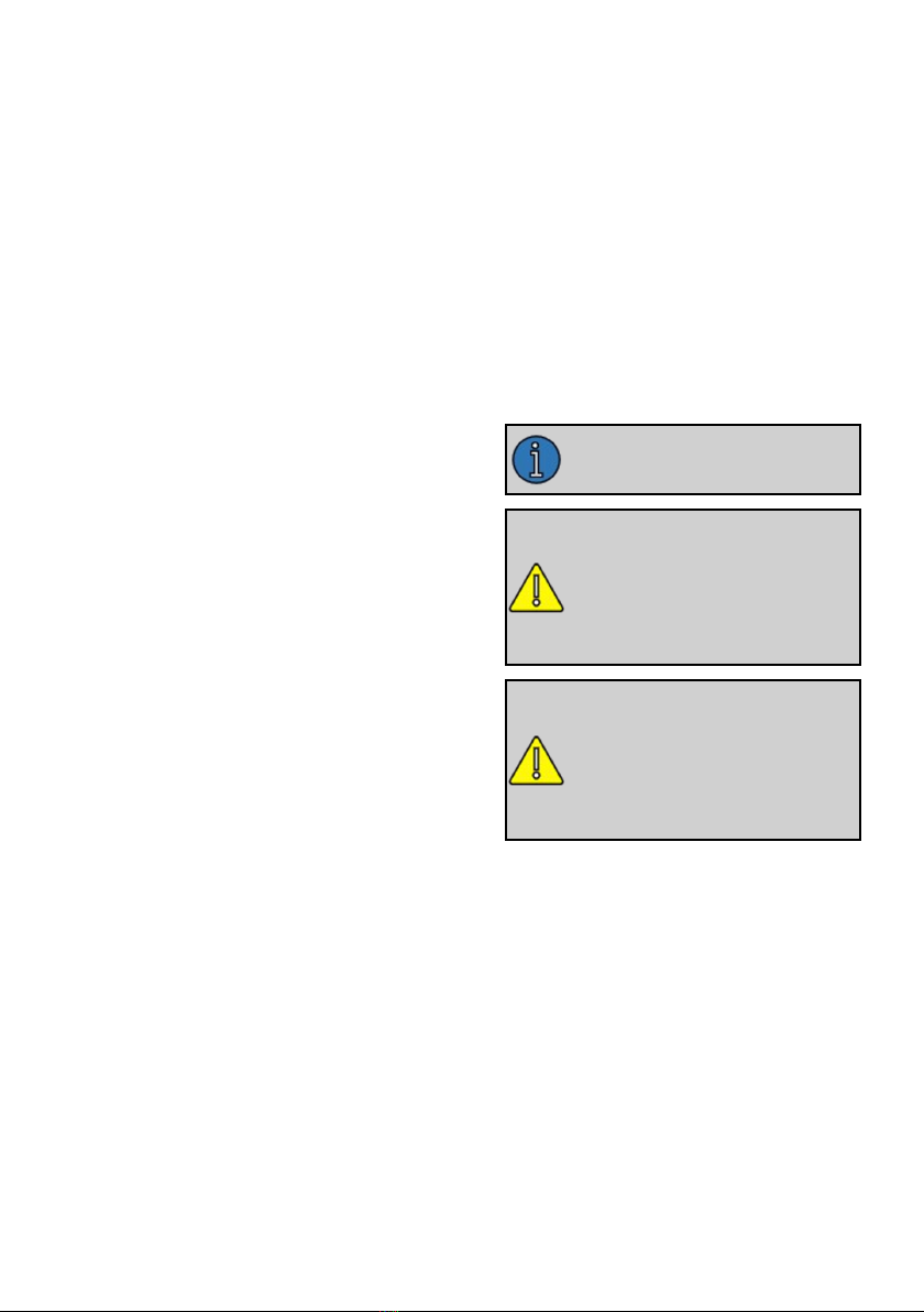
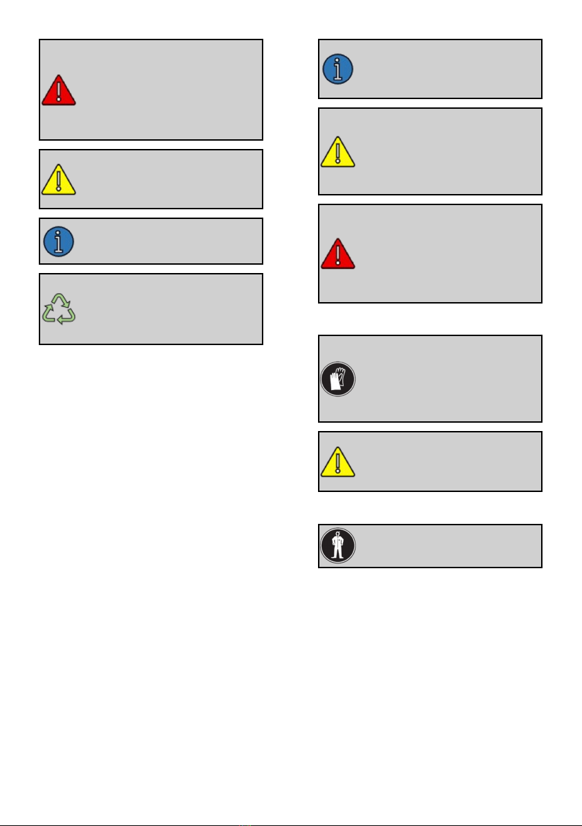
1.2. Meanings of Symbols Used in
User Manual
Several warnings are available in this
manual to ensure maximum safety when
using your vehicle. Each warning is indi-
cated by a special symbol. These sym-
bols and their meanings are as follows.