K1EL Morse Tutor Board MTB
Morse Tutor Manual – v1.1 9/19/2018 Page 2
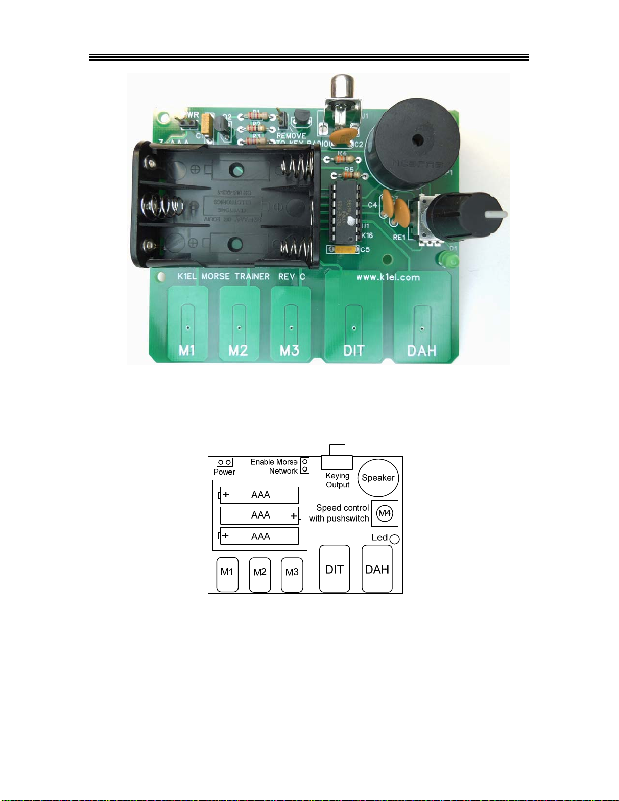
Morse Tutor Board (MTB) Features
•Keyer speed range: 5 - 99 WPM •Integrated Touch Paddle and Pushbuttons
•Touch sensitivity calibration function •34 easy to use commands
•Dynamically allocated message memory •Supply Voltage Monitor
•Keying Modes: Bug, Ultimatic, Iambic A or B •Serial Number Generation
•Rotary Encoder Speed control •Adjustable Letter Spacing: 25 to 75%
•Adjustable Weighting: 25 to 75 % •Automatic letter space mode (Autospace)
•Paddle swap command •Sidetone Output: On board speaker
•Continuously adjustable Sidetone frequency •Optional Key Output: Open collector (60V @120mA)
•Four Push-button user interface •Battery holder for three AAA cells
•Two User Configurations each with callsign •Backspace supported on message entry
•Low Power Consumption: 2 mA idle, 70 uA off •Power on/off by pressing rotary encoder.
•Non-Volatile Message Memory: 232 letters in 10 •Easy access Rx and Tx practice modes
Slots, dual banked, with embedded commands. •Multiple MTBs can be networked together
•Non-Slip Rubber Feet •Message stacking
•Beacon: Programmable interval: 1 to 99 seconds •Board Dimensions: 4.0” by 3.25”
Morse Tutor Description (MTB)
The MTB is designed to be a low cost educational platform for learning and practicing Morse code.
Everything the student needs is on the board including touch pad inputs. Optimal touch paddle sensitivity is
maintained by an auto-calibration algorithm. The MTB is implemented in a Microchip PIC16F1825
microcontroller and utilizes a special version of the K1EL K16 keyer core which provides a wide range of
features. Setup commands are directly entered on the paddles in Morse code. All settings and messages
are stored in nonvolatile memory so that they are preserved when the keyer is turned off. The K16 keyer
core has many original features not found in other keyers:
•Supply Voltage Monitoring
The MTB has a unique feature that is useful in battery powered applications. It can accurately monitor its
supply voltage and provide an indication when battery voltage is low. Normally the MTB will respond with an
Rwhen entering command mode. If the battery voltage is approaching the minimum operating limit, it will
respond with an Linstead. This tells the operator that the batteries need to be replaced. The actual supply
voltage can be read out in Morse by using the Vcommand in the extended command set. (Page 16). The
keyer will continue to operate until the battery voltage falls to approx. 2.7V.
•Dual User Configuration
The MTB provides storage for two complete configuration setups. For example, one setup could be used for
contesting while the other for casual operating. Or, when two operators share the same keyer, each user
can have their own setup profile. The extended command Uis provided to select one configuration or the
other. All MTB settings are included in each profile including a stored callsign. (Page 16)
•Dual Message Banks
The MTB has two message banks of five slots plus two callsign slots. Total message storage is 232 bytes.
While this does not seem like a lot of message space, since the MTB dynamically allocates message
storage in memory, it turns out to be more than adequate for most users. It is very easy to swap message
banks with the Ecommand. This is the shortest command sequence and allows you to swap banks quickly.
There is also a buffered message command /E that swaps message banks within a message. (Page 19)
•Stored Callsigns
Two special memory slots are provided to store a callsign for two users. These callsigns are programmed by
using the callsign load command in the extended command set. A callsign is embedded in a message by
using the /M buffered command. The callsign slot works like any other message slot; you can call other
messages and embed commands, (Page 19)
•Wide range of embedded message commands
Please refer to the list on page 19.