K1EL VLF-B User manual

K1EL VLF-B User Manual VLF - B
Introduction
The VLF B VLF converter allows you to listen to the band of frequencies below the standard M
broadcast band between 10 and 500 Khz. mong the many interesting signals in this VLF range
are long range navigation signals, radioteletype, European broadcasts, and radio beacons. The
VLF-B will convert the range of 10 – 500 KHz to 4010 – 4500 MHz which is just above the
amateur 80 meter band.
Most VLF signals are ground waves and frequently travel over great distances. But you do not
have to cut a long wire antenna to a specific length to receive them, ny length wire vertical or
horizontal will usually provide reasonably good reception but make it as long as you can. tuned
electromagnetic loop is another option for VLF use. These are usually quite expensive to
purchase but it is not too difficult to build your own. loop has two big advantages over a long
wire; noise canceling and ability to rotate it for directional reception.
Wikipedia has a very good article on VLF communications along with typical signals that can be
found on this challenging band.
VLF-B User Manual 11/30/2023 ev 1.0 Page 2

K1EL VLF-B User Manual VLF - B
Block Diagram
The internal components of the VLF-B are illustrated below. radio antenna is connected to the
antenna input SO-239 connector. bypass relay RY1 selects whether the signal passes directly
to the output SO-239 connector or into the converter circuitry. This allows the converter to remain
in line when not enabled. When enabled the signal first passes through a sharp cutoff 8 pole low
pass filter. The filter has a 3 dB corner frequency at approximately 450 KHz. fter the LPF, the
signal is steered either through or around an 8 dB preamplifier by RY2. fter that the signal
passes though the MC1496 converter mixer circuit where it is mixed with a 4 MHz BFO effectively
converting a VLF range of 10 KHz to 500 KHz to an HF range of 4.010 MHz to 4.5 MHz. From
there it passes through RY2 to the output SO239 connector. Microchip PIC processor monitors
two front panel pushbuttons and converts button presses to relay selection for converter and
preamp enable. The current selection is shown via two front panel LEDs which are also controlled
by the PIC. The converter runs on a 12 volt DC supply; two on board regulators produce 9V and
5V to power the mixer and PIC processor.
VLF-B User Manual 11/30/2023 ev 1.0 Page 3

K1EL VLF-B User Manual VLF - B
Operation
The VLF-B requires a DC power supply in the range of 9 to 13.5 volts DC. The current draw is
only 20 m . power supply connector is included. Center pin is positive.
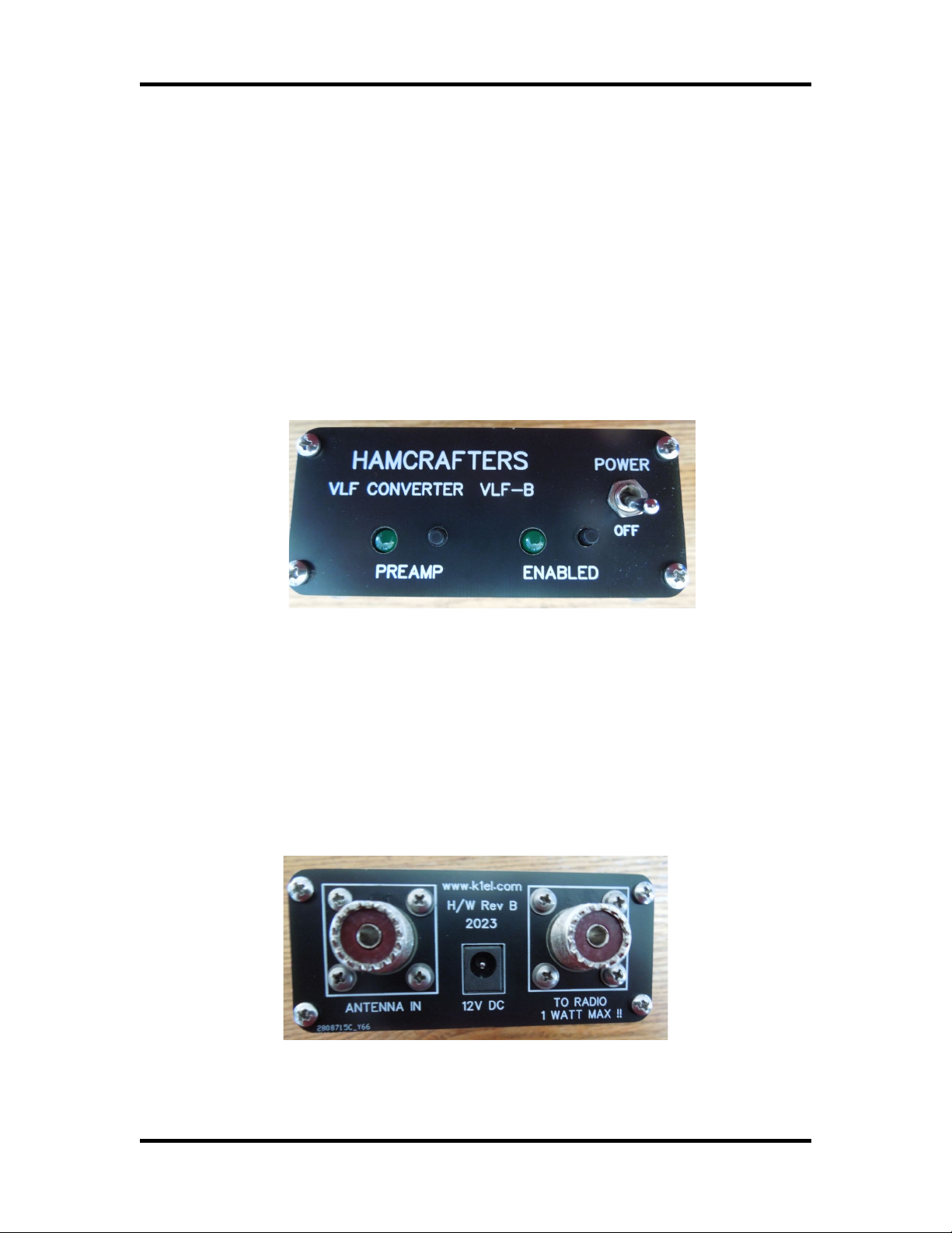
The front panel is shown below. There are only three user controls, power on/off, converter
enable and preselector enable. The signal paths in the VLF-B are controlled by reliable
mechanical relays. Pressing the enable push buttons will toggle the enable state. When enabled,
the accompanying LED will light. When the converter is enabled the signal path will be from the
rear panel antenna input connector, through the converter, and then to the radio output
connector. When the converter is not enabled, the signal path is directly from the antenna input
connector to the radio output connector. Since the path is through mechanical relay switches,
there is no DC offset of stray capacitance to be concerned with. preamplifier is included in the
signal path when it is enabled by the front panel push button. This provide an approximate +8 dB
gain after the front end low pass filter.
The back panel is shown below. The power connector size is 2.1mm with center pin positive. The
SO-239 connector on the left is the antenna input and the SO-239 on the right is the RF output.
When the converter is not enabled the output is directly connected to the input, which is bypass
mode. When enabled, VLF input RF is up-converted to the 4 MHZ band so that it can be received
on an amateur band receiver that has general coverage capability. Note that there is a limitation
on the power level through the converter when it is in bypass mode (converter not enabled).
Please keep power level under 1 watt. In any case it is not a good idea to have the converter in
line with transmitted RF, it’s jut too easy to accidentally transmit through the converter and
permanently damage the sensitive internal circuitry.
VLF-B User Manual 11/30/2023 ev 1.0 Page 4

K1EL VLF-B User Manual VLF - B
Specifications
Input Frequencies 10 to 500 KHz
Output Frequencies 4.010 to 4500 Khz
Sensitivity 1 to 5 uV typical
Input Impedance 50 ohms
Output impedance 50 ohms
Power Requirements 9 to 13.5 VDC at 20 m typical
Dimensions 3.5” W by 5” D (including switch and connectors) by 1.6” H
Net weight 10 oz
Product Warranty, Support, and Liability
VLF B is fully warranted to the original purchaser against defects in materials and workmanship
for one year after purchase. This warranty does not cover damage caused by accident, improper
care, or lightning damage. Please contact us before returning your VLF B for repair and we will
issue an RM .
Please submit support questions by e-mail to [email protected]
While every effort has been made to insure that the VLF B design is safe and the
documentation is clear and accurate, it is still possible to cause equipment damage or
incur personal injury if:
VLF B is not used as intended, VLF B is connected incorrectly, Safety guidelines outlined
in this document are not followed, or VLF B is modified in any way.
K1EL cannot be held responsible in these or other similar events.
VLF B contains no user serviceable components or configurable jumpers. Please do not tamper
with or modify the circuitry of VLF B as this will void its warranty and may result in unsafe
operating conditions.
1
VLF-B User Manual 11/30/2023 ev 1.0 Page 5
Table of contents
Other K1EL Media Converter manuals