K2 Pumps PPV10001SPK User manual

Model: PPV10001SPK
PPV15001SPK
OWNER’S MANUAL
VARIABLE SPEED POOL PUMP
Questions, problems, missing parts? Before returning to the store call
K2 Customer Service 8 a.m. - 6 p.m., EST, Monday-Friday
1-844-242-2475
www.K2pumps.com
Copyright © 2021, GP Enterprises Co., Ltd. K2Man-32 (Rev. 2/18/21)

2 For Professional Technical Support call 1-844-242-2475
PERFORMANCE
SKU HP RPM GPM of Water @ Total Feet of Lift Max. Lift
0 ft. 10 ft. 20 ft. 30 ft. 40 ft. 50 ft.
PPV10001SPK 1
3500 72.0 65.0 56.0 44.0 25.0 / 48 ft.
2000 39.0 20.0 / / / / 16 ft.
1200 22.0 / / / / / 7 ft.
PPV15001SPK 1-1/2
3500 95.0 88.0 80.0 70.0 56.0 40.0 65 ft.
2000 50.0 32.0 7.0 / / / 22 ft.
1200 30.0 / / / / / 8 ft.
SAFETY INSTRUCTIONS
1. DANGER: Do not pump flammable or explosive liquids such as oil, gasoline, kerosene, ethanol, etc. Do not use
in the presence of flammable or explosive vapors. Using this pump with or near flammable liquids can cause an
explosion or fire, resulting in property damage, serious personal injury, and/or death.
2. DANGER: ALWAYS disconnect the power to the pump before servicing.
3. DANGER: Do not touch the motor housing during operation. The motor is designed to operate at high
temperatures. Do not disassemble the motor housing.
4. DANGER: Do not handle the pump or pump motor with wet hands or when standing on a wet or damp surface, or
in water.
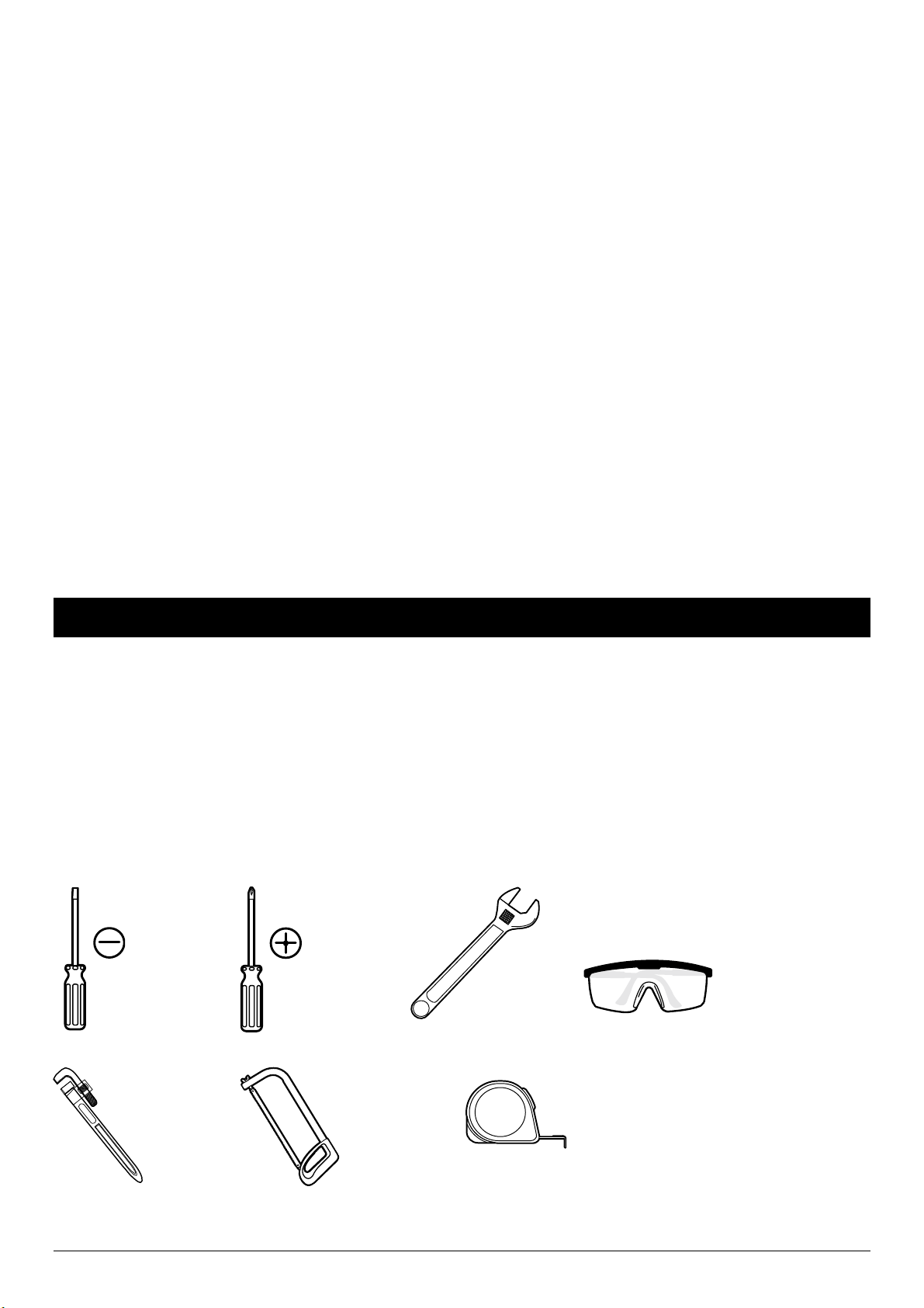
5. WARNING: Wear safety goggles at all times when working with pumps.
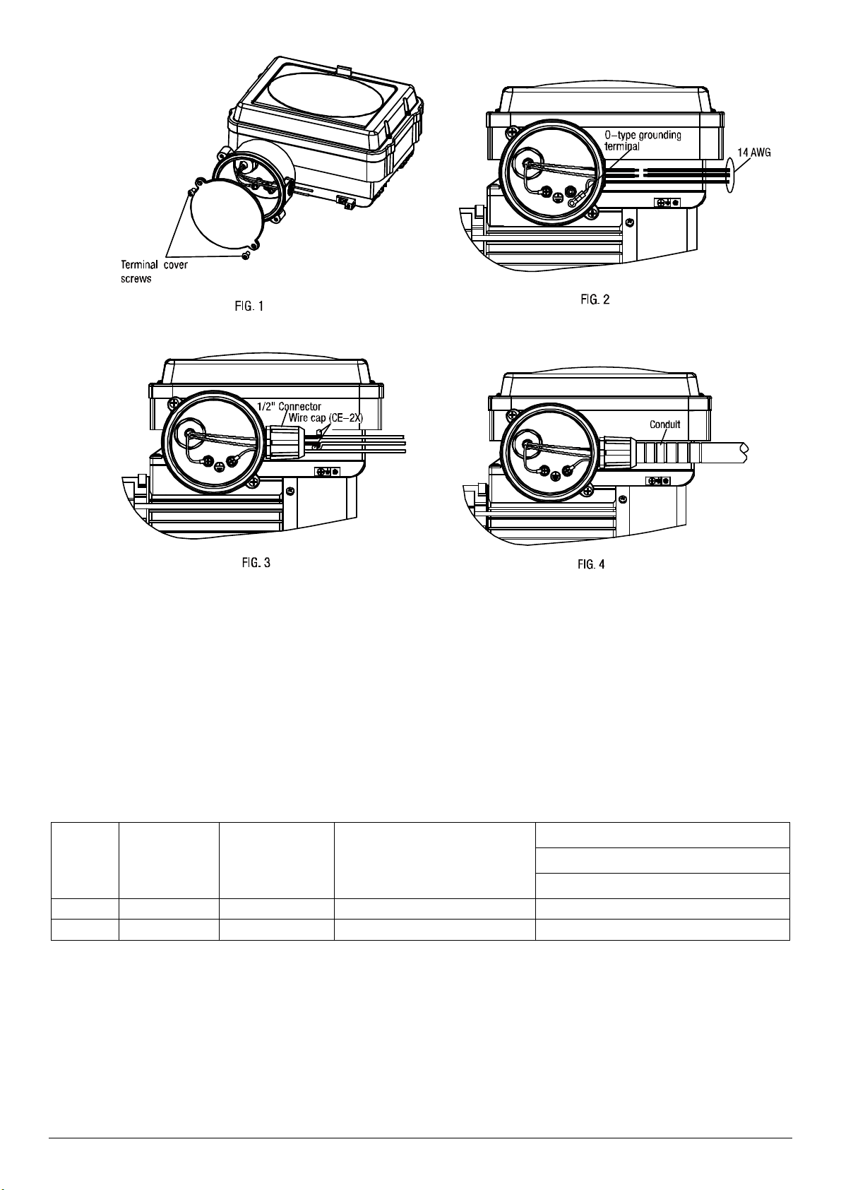
6. WARNING: This is a 230 V pump. All wiring should be performed by a qualified electrician.
7. WARNING: Protect the electrical cord from sharp objects, hot surfaces, oil, and chemicals. Avoid kinking the
cord. Do not use damaged or worn cords.
8. WARNING: Failure to comply with the instruction and designed operation of this unit may void the warranty.
ATTEMPTING TO USE A DAMAGED PUMP can result in property damage, serious personal injury, and/or death.
9. WARNING: The pump should be connected to a GFCI outlet protected with a15 amp (230V) fuse or circuit
breaker.
10. WARNING: Fire and burn hazard. Motors run at high temperatures. Do not allow leaves, debris, or foreign matter
to collect around the pump motor. Allow the motor to cool before handling.
11. CAUTION: Know the pump and its applications, limitations, and potential hazards.
12. CAUTION: Periodically inspect the pump and system components. Disconnect the pump from the power supply
before inspecting.
13. CAUTION: Follow all local electrical and safety codes, along with the National Electrical Code (NEC). In addition,
all Occupational Safety and Health Administration (OSHA) guidelines must be followed.
14. CAUTION: This pump is for use with permanently installed pools. Do not use with storable pools. A permanently
installed pool is constructed in or on the ground or in a building and is not intended to be disassembled or moved.
15. CAUTION: Use rigid or flexible PVC pipe. Ensure pipe ends are clean and free of any flash caused by cutting.
Use proper glue for the type of pipe selected.
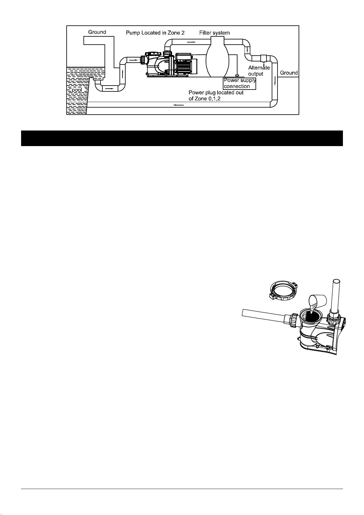
16. CAUTION: Locate pump on a non-combustible surface as close to the pool/spa as possible. The surface should
be hard, level, dry, and well ventilated. The surrounding area should provide protection from the elements and
allow sufficient space for maintenance and service. Ensure the drainage will flow away from the pump. To reduce
vibration and pipe stress, use anchor bolts to secure the pump base to the surface.

For Professional Technical Support call 1-844-242-2475 3
17. CAUTION: Use a supplier recommended primer to ensure glued joints are secure. Many local codes require
primer with a purple tracer to verify primer use.
18. CAUTION: Consider climatic conditions when applying adhesives. Atmospheric conditions with high humidity will
make the adhesive action of certain glues less effective. Follow the manufacturer's instructions.
19. CAUTION: This pump should be installed and serviced only by a qualified pool service professional. Installers,
pool operators and owners must read these warnings and all instructions in the owner’s manual before using this
pump. These warnings and the owner’s manual must be left with the pool owner.
20. IMPORTANT: Design the piping system to allow the pump suction inlet height to be as close to the water level as
possible. Mount the pump below water level for easy priming. If the pump must be located above the filled water
level, keep the vertical distance to a minimum. Use short, direct piping to the suction to minimize friction loss.
21. IMPORTANT: The motor of this pump has a thermal protector that will trip if the motor becomes too hot. The
protector will reset it-self once the motor cools down and an acceptable temperature has been reached. The
pump may start unexpectedly if it is plugged in.
22. IMPORTANT: Ensure the electrical power source is adequate for the requirements of the pump.
23. IMPORTANT: This pump is made of high-strength, corrosion-resistant materials. It will provide trouble-free
service for a long time when properly installed, maintained, and used. However, inadequate electrical power to
the pump, dirt, or debris may cause the pump to fail. Please carefully read the manual and follow the instructions
regarding common pump problems and remedies.
24. IMPORTANT: Provide sufficient ventilation to maintain air temperature below the maximum ambient temperature
rating shown on the motor nameplate. Any enclosure or pump house must allow adequate ventilation to assure
the ambient temperature remains below the motor rating when the pump is operating.
PRE-INSTALLATION
APPLICATION
This swimming pool pump is designed for use with permanently installed swimming pools only. A permanently installed
pool is constructed in or on the ground or in a building and is not intended to be disassembled or moved.
Do not use with storable portable pools. A storable pool is constructed so that it may be readily disassembled for
storage and reassembled to its original integrity.
TOOLS REQUIRED
Phillips
Screwdriver
Flathead
Screwdriver
Safety
Goggles
Pipe Wrench Hacksaw Tape Measure
Wrench

4 For Professional Technical Support call 1-844-242-2475
PACKAGE CONTENTS
Part Description QTY
A Pump 1
B Union Nut 2
C Union Adapter 2
D O-ring 2
MATERIALS REQUIRED (NOT INCLUDED)
Additional items needed QTY
Teflon tape As needed
Rigid pipe As needed
Ball Valve As needed
Union As needed
Elbow As needed
Adapter 2
Tee As needed
PVC cement 1
IAPMO Certified Anti-entrapment Cover As needed
SPECIFICATIONS
Power supply 230V, 60 HZ., 15 Amp Circuit
Liquid temp. range 32 to 100°F (0- 38°C)
Discharge size 1 -1/2 in. NPT thread with adaptor
INSTALLATION
Only qualified, licensed personnel should install pump and wiring.
The pump mount must be located away from corrosive or flammable chemicals.
THREADED CONNECTIONS
Use only PTFE tape or equivalent on threaded plumbing
connections. Other pipe compounds may damage threads. Do
not use silicone or petroleum based compounds. Do not over tighten.
Hand tightening plus 1/2 turn is sufficient.

For Professional Technical Support call 1-844-242-2475 5
PUMP PLUMBING
Suction pipe should be as large as or larger than discharge pipe. Avoid using a suction pipe smaller than the pump
connection. The pump is designed to accept 1-1/2 in. suction piping.
1. Keep the piping as straight and short as possible, and of suitable size.
2. Avoid connecting an elbow directly into the pump inlet. A length of straight pipe will allow proper entry of the water
to the pump.
3. Slope horizontally, and run upward to the pump to prevent trapping air.
4. Use independent piping supports for suction and discharge pipes to reduce strain on the pump.
5. Keep as much of the suction line as possible below the water level to reduce priming time.
6. Install valves and unions in the pump suction and return the lines to facilitate servicing. Valves are also essential for
pump maintenance, if the system is installed below deck level.
NOTICE: Use PTFE tape for making threaded connections to the pump. Do not use pipe dope.
Thread sealant tape instructions:
Use only new or clean PVC pipe fittings.
Wrap male pipe threads with one to two layers of PTFE tape. Cover entire threaded portion of pipe.
Do not overtighten or tighten past thread stop in pump port!
If leaks occur, remove pipe, clean off old tape, rewrap with one to two additional layers of tape and remake the
connection.
NOTICE: Support all piping connected to pump!
Fittings
Fittings restrict flow; for best efficiency use the fewest number of possible fittings. Avoid fittings which could cause an
air trap. Pool fittings must conform to International Association of Plumbing and Mechanical Officials (IAPMO)
standards. Use only non-entrapping suction fitting or double suction.
POOL PUMP SUCTION REQUIREMENTS
WARNING: Pump suction is hazardous and can trap, drown, or disembowel bathers. Do not use or operate swimming
pools, spas, or hot tubs if a suction outlet cover is missing, broken, or loose. Follow the guidelines below for a pump
installation which minimizes risk to all users of pools, spas, and hot tubs.
Entrapment Protection
The pump suction must be designed to eliminate the possibility of suction entrapment or hair
entrapment/entanglement.
Suction Outlet Covers
All suction outlet covers must be maintained. They must be replaced if cracked, broken, or missing.
See Testing and Certification for outlet cover certification requirements.
All suction outlets must have correctly installed, screw fastened covers in place.
Testing and Certification
All suction inlet covers must comply with ASME/ANSI specifications for suction fittings for use in swimming pools,
spas, hot tubs, and whirlpool bathtub applications. The product must be tested for compliance with the standards, and
the certification must be included with the components.

6 For Professional Technical Support call 1-844-242-2475
Suction inlets must be designed so that water is drawn simultaneously. A vacuum relief device can be installed in line
leading to the pump suction.
All suction outlet covers must conform to ASME/ANSI A112.19.18M; or must be a minimum 18 x 23 grate or larger; or
must have an approved channel drain system. Skimmers are exempted. All pool and spa single or multiple outlet
circulation systems shall be equipped with an atmospheric vacuum relief system. The system must be ASME/ANSI
A112.19.17 Rated.
Any pool or spa shall immediately be closed if the cover or grate is damaged or missing.
Suction outlet covers/grates shall be tested and listed by a nationally recognized testing laboratory as conforming to
ASME/ANSI A112.19.8
ELECTRICAL
Ground the motor before connecting to electrical power supply. Failure to ground the motor may cause severe or fatal
electrical shock hazard. Never ground to a gas supply line.
To avoid dangerous or fatal electrical shock, turn OFF power to motor before working on electrical connections.
Ground Fault Circuit Interrupter (GFCI) tripping indicates an electrical problem. If GFCI trips and will not re-set, have a
qualified electrician inspect and repair electrical system.
Verify that supply voltage matches the nameplate voltage. Incorrect voltage can cause fire or seriously damage motor
and voids warranty.
Voltage
Voltage at motor must be within 10% of the motor nameplate rated voltage or motor may overheat, causing overload
tripping and reduced component life. If voltage does not fall within the specified range during operation consult the
power company.
Grounding/Bonding
Install, ground, bond and wire motor according to local or National Electrical Code requirements. Permanently ground
the motor. Use the ground terminal provided in the terminal box on the back of the motor. Use size and type wire
required by local codes. Connect motor ground terminal to electrical service ground.
Bond motor to pool structure. Use a solid copper conductor, size No.14 AWG or larger. Run wire from external
bonding lug to reinforcing rod or mesh.
To Wire a Variable Speed Motor
NOTICE: Be sure power is off.
Remove the terminal box lid (FIG.1)
Using multi-function crimping pliers to press o-type grounding terminal which connected 14 AWG. (FIG.2)
Install 1/2” connector to terminal box. Install ground wire to ground rod. using multi-function crimping pliers to
connect two wires with two wire caps. (FIG.3)
Install conduit to connector. (FIG.4)
Re-install the terminal box lid.

For Professional Technical Support call 1-844-242-2475 7
Connect a No. 8 AWG solid copper bonding wire to the pressure wire connector provided on the motor housing and to
all metal parts of the swimming pool, spa, or hot tub and to all electrical equipment, metal piping or conduit within 5
feet of the inside walls of swimming pool, spa, or hot tub.
Follow all national and local wiring codes. If unsure of the code requirements, consult a professional electrician.
Pump must be permanently connected to circuit. Table I gives correct wire and circuit breaker sizes for the pump
alone. If other lights or appliances are also on the same circuit, be sure to add their amp loads to pump amp load. If
unsure, consult a licensed electrician.
A Ground Fault Circuit Interrupter (GFCI) is required in the circuit. For size of GFCI required and test procedures for
GFCI, please see manufacturer’s instructions.
Table l- Recommended Fusing Data
Motor
HP
Branch Fuse
Rating
Amps*
Max Load
Amps Voltage/Hz/Phase
Service to Motor – Distance in Ft. (m)
0-300’ (0-30)
AWG Wire Size (mm2)
1 15 3.3 230/60/1 14 (2)
1-1/2 15 5.0 230/60/1 14 (2)
* Time delay fuses are recommended instead of standard fuses in any motor circuit.
MECHANICAL TROUBLES AND NOISE
1. If suction and discharge piping are not adequately supported, pump assembly will be strained. Use independent
piping supports for suction and discharge pipes to reduce strain on the pump.
2. Do not mount the pump on a wooden platform! Securely mount on a concrete platform for quietest performance
before working on pump or motor.

8 For Professional Technical Support call 1-844-242-2475
OPERATION
Avoid running pump dry. Fill pump with water before starting motor. Before removing trap cover:
1. STOP PUMP before proceeding.
2. CLOSE GATE VALVES in suction and discharge pipes.
3. RELEASE ALL PRESSURE from pump and piping system.
4. If pump is being pressure tested, be sure pressure has been released before removing trap cover.
WARNING: Do not block pump suction. To do so with body may cause severe or fatal injury. Small children using pool
must ALWAYS have close adult supervision.
WARNING: Fire and burn hazard. Motor runs at high temperatures, to reduce the risk of fire, do not allow debris, or
foreign matter to collect around the pump motor. Allow motor to cool prior to handling or performing maintenance.
The motor is equipped with an internal thermal protection circuit to guard against overheating. The maximum ambient
temperature for motor operation must not exceed rating on motor model plate.
Priming Pump
Release all pressure from filter, pump, and piping system; see the filter owner’s
manual. In a flooded suction system (water source higher than pump), pump
will prime automatically during suction and discharge valves are opened.
If the pump is located above the normal pool water level, remove ring and trap
assembly, and fill trap and pump with water. Clean and inspect O-ring; then
reinstall on trap cover. Replace trap cover assembly on trap, then rotate
clockwise to tighten cover.
NOTICE: Tighten ring and cover assembly by hand - do not use tools. Pump
priming time will depend on the vertical distance and length of the suction line.
The pump is designed to prime at 10 ft. or less. If the pump does not prime, make sure that all valves are open, and
that the suction pipe is submerged. Verify there are no leaks in the suction lines.
Routine Maintenance
The only routine maintenance needed is the inspection and cleaning of the trap basket. Debris or trash that collects in
the basket will choke off water flow through the pump.
Before attempting to clean the basket:
1. Stop pump, close valves in suction and discharge, and release pressure from system.
WARNING: Hazardous suction can trap hair or body parts, causing severe injury or death. Do not block suction.
2. Remove the ring and cover assembly by turning counter clockwise. If necessary, tap handles gently with a rubber
mallet.
3. Remove the basket and clean. Inspect holes in basket for blockage. Clean the basket with water and replace in
trap. Verify that the basket is oriented correctly in pump housing.

For Professional Technical Support call 1-844-242-2475 9
4. Clean and inspect lid O-ring; then reinstall the ring and cover assembly.
5. Prime the pump (see priming instructions).
Draining the Pump
A. Pump down water level below all inlets to the pool.
WARNING: To avoid dangerous or fatal electrical shock hazard,
turn OFF power to the motor before draining pump.
B. Remove the trap cover.
C. Drain the basket housing and pump housing through the drain
plugs
D. Clean the pump and basket, then replace cover assembly.
E. Be sure motor is kept dry and covered.
NOTICE: Tighten trap cover by hand only.
Storage/Winterizing:
WARNING: Explosion hazard. Purging the system with
compressed air can cause components to explode, with risk of
severe injury or death to anyone nearby. Use only a low pressure (below 5 PSI), high volume blower for purging the
pump, filter, or piping.
For outdoor/unprotected installations:
1. Enclose entire system in a weather proof enclosure.
2. To avoid condensation/corrosion damage, allow ventilation; do not wrap system in plastic.
3. Use a 40% propylene glycol/60% water solution to protect pump to -50°F (-46°C).
NOTICE: Allowing pump to freeze will damage pump and void warranty!
NOTICE: Use only non-toxic antifreeze. Do not use automotive antifreeze. It is highly toxic and may damage plastic
components in the system.
Operation of Control Panel
This series of swimming pool pumps are equipped with human-machine
interface, which can display the current time, pump start and stop state,
current speed and working mode in real time. You can also set the working
mode and current time through the buttons on the panel, where the working
mode can be automatic or manual.
As shown in the figure below, the upper part is the LCD display area,
respectively shows:
1. The current time, as shown in the figure, is currently 12:00.
2. As shown in the figure, the current speed is 3300RPM and the gear is
HIGH.
3. Start and stop time period and gear in automatic mode, as shown in the
figure, the first start and stop time period in automatic mode is 8:00-
14:00, and the operating gear is HIGH.
4. Working mode. The mode is divided into MANUAL and AUTO, as shown
in the figure for MANUAL file.
5. Pump operation indication, impeller rotation indicates pump operation,
animation icon rotation speed will change according to the high, middle
and low three gears.

10 For Professional Technical Support call 1-844-242-2475
1. Pump operation mode
In the automatic mode,4 working periods can be set every day, and the rotation speed of the four working periods can
be set to different speeds, among which the rotation speed is adjustable 600RPM~3500RPM.If the current time is within
the period set by the user, the pump will work according to the start and stop time and the set rotation speed set by the
user. Under the automatic mode, the default startup time is high speed 3500RPM for 5 minutes. After 5 minutes, the
startup time will be automatically switched to the speed set by the customer.
In manual mode, the user controls the start and stop of the pump by pressing the start and stop button, and the speed
can be passed through the panel
,,,
three buttons to switch, can also go through “ ” “ ”button
to adjust the speed ,press the “ ”or “ ”button every time, speed increase or decrease 25RPM,adjustable range
is 600RPM~3500RPM.
LOW: 1200 MEDIUM: 2000 HIGH: 3500
Power on default manual mode
Press AUTO to start manuall
y
Put AUTO manual mode on again and stop
Press AUTO again
Press AUTO a
g
ain to close the auto mode

For Professional Technical Support call 1-844-242-2475 11
2. Set pump parameters
3.Set time
Long press for more than 3 seconds to enter the setting mode and enter the setting time state. The 12 of
start flashing, you can go through and to adjust the hours. Press to confirm, and
enter the mode of setting minutes. At this time, the flash starts, it can also be adjusted by and .When
the time is adjusted, the setting will be automatically saved in 10 seconds, and the setting time mode will exit to enter
the working mode.
4. Set working time and speed
In the setting mode, after setting the current time, it will automatically enter the setting time period 1 mode. At this time,
you can set the start time and stop time of the pump as well as the running speed. When in starts
flashing, the time can be adjusted through and , press to confirm, and so on,after when set the start
time and stop time, start flashing, at this time for the first time running speed, we can set the speed by
Long press the set key for 3 seconds
Set time mode
Set the time and s
p
eed of time
p
eriod 1
Set the time and s
p
eed of time
p
eriod 2
Set the time and s
p
eed of time
p
eriod 3
Set the time and s
p
eed of time
p
eriod 4
To exit the setting mode, do not press the button
for 10
s
ec
o
nd
s

12 For Professional Technical Support call 1-844-242-2475
, also can adjust speed by and ,when press ,automatic recording speed and enter the set
period 2,and so on. The first time period can be set to a maximum of 0:00-23:59. The second time period can be set as
the maximum time period (stop time of the first time period-23:59). Time periods 3 and 4 are turned off by default and
can be turned on by either or .When the settings are complete, wait 10 seconds for the system to
automatically save the settings. Example 1: The first time period is 8:00-23:59, the second time period is 23:59-23:59,
the third time period is off, and the fourth time period is 00:00-03:00. At this time, the pump will run from 8am to 3am the
next day.
Press in manual or automatic mode to toggle the display of each set period.
When the fault code is displayed, press to reset the fault.
5. Close/turn on the LCD backlight
Press to turn on/off the LCD backing.
6. Fault code description
: Communication failure.
Please check whether the connection line between the display board (upper board) and the drive board (lower board)
is loose.
: Supply voltage error.
The normal power supply voltage is 230V±10%,please check whether the power supply voltage is normal.
: Locked-rotor protection.
Please check whether the motor is blocked
: Motor open phase.
Check whether the motor connection is normal.
: Drive overheating.
CARE AND CLEANING
Pump should only be serviced by qualified personnel. For best results, use only genuine factory parts. Be sure to
prime pump before starting.
WARNING: Risk of explosion. Before beginning pump service.
1. Stop pump before proceeding.
2. Close gate valves in suction and discharge pipes.
3. Release all pressure from pump and piping system.
WARNING: Risk of electric shock. Can shock, burn or kill. Disconnect power before working on pump or motor.
When using factory authorized parts, no lubrication or regular maintenance is needed beyond reasonable care and
periodic cleaning of the strainer basket.
If shaft seal is worn or damaged, repair as follows:

For Professional Technical Support call 1-844-242-2475 13
Pump Disassembly/Removing Old Seal
Before disassembly, disconnect power to pump
motor. Be sure gate valves on suction and
return piping are closed. Release all pressure
by opening all vents.
1. Drain pump by removing drain plugs on
bottom of pump body and trap body.
2. Be sure there is no pressure in trap body;
remove cover (unscrew by turning counter-
clockwise).
3. Remove eight nuts, lock washers and flat
washers holding seal plate to pump body.
Pull seal plate and motor away from pump body. You may have to CAREFULLY use a screwdriver to separate
body from seal plate.
4. Remove two screws holding diffuser to seal plate. Remove diffuser.
WARNING: Hazardous voltage. Capacitor voltage may be hazardous.
To discharge motor capacitor, hold insulated handle screw driver BY THE
HANDLE and short capacitor terminals together. Do not touch metal
screwdriver blade or capacitor terminals. If in doubt, consult a qualified
electrician.
5. Hold shaft with flat-head screw on motor shaft flats.
6. Unscrew impeller from shaft (turn counter clockwise when facing it).
7. Remove four screws holding seal plate to motor.
8. Place seal plate face down on flat surface and tap out ceramic seat.
9. Clean seal cavity in seal plate and clean motor shaft.
Pump Reassembly/Installing New Seal
1. Ceramic seat must be clean and free of dirt, grease, dust, etc. Wet outer edge
with small amount of liquid detergent; press ceramic seat into seal plate cavity
firmly and squarely with finger pressure.
2. If ceramic seat will not locate properly, remove it, place face up on bench and
re-clean cavity. Ceramic seat should now locate.
3. If seat still will not locate properly, place a cardboard washer over the polished
face and use a piece of 3/4 in. (19 mm) standard pipe for pressing purposes.
NOTICE: Do not scratch or mar polished surface or seal will leak.
4. Remount seal plate on motor. Tighten bolts to 60-80 inch-lbs. (69-92 kg/cm)
torque.
5. Apply a small amount of liquid detergent to inside diameter of rotating half of seal.
6. Slide rotating seal member, polished carbon face out, over impeller sleeve until rubber drive ring hits back of
impeller.
NOTICE: Do not nick or scratch polished seal face; seal will leak if face is damaged.
7. Screw impeller onto shaft (clockwise); this will automatically locate seal in seal plate.
8. Mount diffuser on seal plate.
9. Assemble motor and seal plate to pump body with nuts, flat washers and lock washers. Torque nuts to 120-130 in-
lbs. (138-150kg/cm).
10. Prime pump according to instructions in Priming Pump.

14 For Professional Technical Support call 1-844-242-2475
TROUBLESHOOTING
Read and understand safety and operating instructions in this manual before doing any work on pump!
Only qualified personnel should electrically test the pump motor! FAILURE TO PUMP; REDUCED CAPACITY OR
DISCHARGE PRESSURE.
Problem Possible Cause Corrective Action
The pump does not pump
water.
The pump is not priming.
1. Pump must be primed. Make sure that pump
body and basket body are full of water. See
primin
g
instructions.
There are leaks in the suction
pipin
g
.
2. Make sure there are no leaks in suction
pipin
g
.
The suction inlet is above water
level.
3. Make sure suction inlet is well below the
water level to prevent pump from suckin
g
air.
The vertical distance of the
pump is too high to water lever.
4. Pump is designed to prime at a vertical
distance of 10 ft. or less. Verify suction lift is 10
ft or less. Lower pump closer (vertically) to
water source.
The pump is clogged.
1. Make sure suction trap is not clogged; if it is,
then clean trap and strainer.
2. Make sure the impeller is not clo
gg
ed
The impeller and diffuser are
worn.
3. Impeller and diffuser may be worn. If so,
order replacement parts. For more information
call customer service.
The pump is incorrect for this
installation.
4. The pump may be trying to push too high a
column of water. If so, a “higher head” pump is
needed.
The pump is experiencing
electrical issues. The voltage is incorrect.
1. Pump may be running too slowly; check
voltage at motor terminals and at meter while
pump is running. If low, see wiring instructions
or consult power company. Check for loose
connections
2. Pump may be too hot.
A. Check line voltage; if less than 90% or more
than 110% of rated voltage consult a licensed
electrician.
B. Increase ventilation.
C. Reduce ambient temperature.
D. Ti
g
hten an
y
loose connections.
The pump is experiencing
mechanical troubles and
noise.
There are issues with the piping.
1. If suction and discharge piping are not
adequately supported, pump assembly will be
strained. See “Installation”.
The pump is improperly
mounted.
2. Do not mount the pump on a wooden
platform! Securely mount on a concrete
platform for quietest performance before
workin
g
on pump or motor.

For Professional Technical Support call 1-844-242-2475 15
WARRANTY
K2 Pumps Limited Warranty
WHAT THIS WARRANTY COVERS
This Limited Warranty is effective September 1, 2020 and replaces all undated warranties dated prior to
September 1, 2020.
K2 Pumps (K2) warrants to the original consumer purchaser (You) that its products are free from original defects
in material and workmanship for at least one year (warranty varies depending on model; see box or K2 website
for specific warranty information) from the date of purchase (the Warranty Period). Repair Parts and Accessories
are warranted for 90 days from the date of purchase. During the Warranty Period, K2 will repair or replace, at no
cost to you, products that have been examined by K2 and found to be defective in materials or workmanship.
Do not return product to the retail store.
For technical support and parts, call K2 Customer Service at 844-242-2475.
WHAT THIS WARRANTY DOES NOT COVER
This Warranty does not cover use of the product in a non-residential application, improper installation and/or
maintenance of the product, damage due to misuse, acts of God, nature, vandalism or other acts beyond control
of K2, owner’s acts or omissions, use outside the country in which the product was initially purchased and resale
of the product by the original owner. This warranty does not cover pick up, delivery, transportation or house calls.
However, if you mail your product to a K2 Sales and Service Center for warranty service, cost of shipping will be
paid one way. This warranty does not apply to products purchased outside of the United States, including its
territories and possessions, outside of U.S. Military Exchange and outside of Canada. This warranty does not
cover products purchased from a party that is not an authorized retailer, dealer or distributor of K2 products.
OTHER IMPORTANT TERMS
This warranty is not transferable and may not be assigned. This Warranty shall be governed and construed
under laws of the state of Michigan. The Warranty Period will not be extended by any replacement or repair
performed under this Warranty. THIS WARRANTY IS THE EXCLUSIVE WARRANTY AND REMEDY
PROVIDED BY K2. ALL OTHER WARRANTIES, EXPRESSED OR IMPLIED, INCLUDING WARRANTIES OR
MERCHANTABILITY OR FITNESS FOR PARTICULAR PURPOSE, ARE DISCLAIMED. IN NO EVENT WILL K2
BE LIABLE FOR ANY SPECIAL, INDIRECT, INCIDENTAL OR CONSEQUENTIAL DAMAGES OF ANY KIND
OR NATURE TO OWNER OR ANY PARTY CLAIMING THROUGH OWNER WHETHER BASED IN
CONTRACT, NEGLIGENCE, TORT, OR STRICT PRODUCTS LIABLITY OR ARISING FROM ANY CAUSE
WHATSOEVER. Some states do not allow for the exclusion of consequential damages, so the above exclusion
may not apply to you. This warranty gives you specific rights. You may also have other rights that vary from state
to state.
GP Enterprises Co., Ltd. 1436 Brook Drive, Downers Grove, IL 60515
Phone: 844-242-2475 / Web: www.K2Pumps.com


Modelo: PPV10001SPK
PPV15001SPK
MANUAL DEL PROPIETARIO
BOMBA DE VELOCIDAD VARIABLE
PARA PISCINAS
¿Preguntas, problemas, piezas faltantes? Antes de regresar a la tienda,
comuníquese con el servicio de atención al cliente de K2 de 8 a.m. a 6 p.m.,
hora del este (EST), de lunes a viernes
1-844-242-2475
www.K2pumps.com

2 Para obtener asistencia técnica profesional, llame al 1-844-242-2475
RENDIMIENTO
Modelo HP RPM
GPM de agua a pies totales de elevación (alta velocidad) Elevación
máx.
0 pies 10 pies 20 pies 30 pies 40
pies 50 f pies.
PPV10001SPK 1
3500 72.0 65.0 56.0 44.0 25.0 / 48 ft.
2000 39.0 20.0 / / / / 16 ft.
1200 22.0 / / / / / 7 ft.
PPV15001SPK 1-1/2
3500 95.0 88.0 80.0 70.0 56.0 40.0 65 ft.
2000 50.0 32.0 7.0 / / / 22 ft.
1200 30.0 / / / / / 8 ft.
INSTRUCCIONES DE SEGURIDAD
1. PELIGRO: No bombee líquidos inflamables o explosivos, como aceite, gasolina, queroseno, etanol, etc. No utilizar en
presencia de vapores inflamables o explosivos. El uso de esta bomba con líquidos inflamables, o cerca de ellos, puede
causar una explosión o un incendio, lo que puede provocar daños materiales, lesiones personales graves o la muerte.
2. PELIGRO: Desconecte SIEMPRE la fuente de alimentación de la bomba antes de hacerle el mantenimiento.
3. PELIGRO: No toque la carcasa del motor durante el funcionamiento. El motor está diseñado para funcionar a altas
temperaturas. No desmonte la carcasa del motor.
4. PELIGRO: No manipule la bomba o el motor con las manos mojadas o cuando esté parado sobre una superficie
mojada o húmeda, o en el agua.
5. ADVERTENCIA: Use gafas de protección en todo momento cuando trabaje con bombas.
6. ADVERTENCIA: Esta es una bomba de 230 V. Todo el cableado debe ser conectado por un electricista calificado.
7. ADVERTENCIA: Proteja el cable eléctrico de objetos afilados, superficies calientes, aceite y productos químicos. Evite
torcer el cable. No utilice cables dañados o gastados.
8. ADVERTENCIA: No respetar las instrucciones y el funcionamiento previsto de esta unidad puede anular la garantía.
INTENTAR UTILIZAR UNA BOMBA DAÑADA puede provocar daños materiales, lesiones personales graves o la
muerte.
9. ADVERTENCIA: La bomba debe conectarse a un tomacorriente con interruptor de falla a tierra (GFCI) protegido con
un fusible o disyuntor de 15 amperios (230 V).
10. ADVERTENCIA: Peligro de incendio y quemaduras. Los motores funcionan a altas temperaturas. No permita que se
acumulen hojas, residuos o materiales extraños alrededor del motor de la bomba. Deje que el motor se enfríe antes de
manipularlo.
11. PRECAUCIÓN: Conozca la bomba y sus usos, limitaciones y peligros potenciales.
12. PRECAUCIÓN: Revise periódicamente la bomba y los componentes del sistema. Desconecte la bomba de la fuente
de alimentación antes de la revisión.
13. PRECAUCIÓN: Cumpla todos los códigos eléctricos y de seguridad locales, junto con el Código Eléctrico Nacional
(National Electrical Code, NEC). Además, se deben seguir todas las pautas de la Administración de Salud y Seguridad
Ocupacional (Occupational Safety and Health Administration, OSHA).
14. PRECAUCIÓN: Esta bomba se debe usar con piscinas instaladas de manera permanente. No la use con piscinas
almacenables. Una piscina permanente se construye en o sobre el suelo o en un edificio, y no está diseñada para ser
desmontada o movida.
15. PRECAUCIÓN: Utilice un tubería de PVC rígida o flexible. Asegúrese de que los extremos de la tubería estén limpios y
libres de rebabas causadas por el corte. Utilice el pegamento adecuado para el tipo de tubería seleccionado.
16. PRECAUCIÓN: Coloque la bomba sobre una superficie no combustible, lo más cerca posible de la piscina o
hidromasaje. La superficie debe estar dura, nivelada, seca y bien ventilada. El área circundante debe brindar
protección contra la intemperie, y permitir suficiente espacio para el mantenimiento y el servicio. Asegúrese de que el
drenaje descargue lejos de la bomba. Para reducir la vibración y la tensión de la tubería, use pernos de anclaje para
asegurar la base de la bomba a la superficie.
17. PRECAUCIÓN: Utilice un cebador recomendado por el proveedor para garantizar que las juntas pegadas estén
seguras. Muchos códigos locales exigen un cebador con un trazador púrpura para verificar su uso.

Para obtener asistencia técnica profesional, llame al 1-844-242-2475 3
18. PRECAUCIÓN: Tenga en cuenta las condiciones climáticas al aplicar los adhesivos. Las condiciones atmosféricas con
alta humedad harán que la acción adhesiva de ciertos pegamentos sea menos eficaz. Siga las instrucciones del
fabricante.
19. PRECAUCIÓN: Esta bomba debe ser instalada y reparada solo por un profesional calificado de servicio de piscinas.
Los instaladores, operadores de piscinas y propietarios deben leer las advertencias y todas las instrucciones del
manual del propietario antes de usar esta bomba. El propietario de la piscina debe guardar estas advertencias y el
manual.
20. IMPORTANTE: Diseñe el sistema de tuberías para permitir que la altura de entrada de succión de la bomba esté lo
más cerca posible del nivel del agua. Monte la bomba por debajo del nivel del agua para facilitar el cebado. Si la
bomba debe ubicarse por encima del nivel del agua llena, mantenga la distancia vertical al mínimo. Utilice una tubería
corta y directa a la succión para reducir al mínimo la pérdida por fricción.
21. IMPORTANTE: El motor de esta bomba tiene un protector térmico que se disparará si el motor se calienta demasiado.
El protector se reiniciará automáticamente una vez que el motor se enfríe y se haya alcanzado una temperatura
aceptable. La bomba puede arrancar inesperadamente si está enchufada.
22. IMPORTANTE: Asegúrese de que la fuente de alimentación eléctrica sea adecuada para los requisitos de la bomba.
23. IMPORTANTE: Esta bomba está hecha de materiales de alta resistencia y resistentes a la corrosión. Proporcionará un
funcionamiento sin problemas durante mucho tiempo si se instala, mantiene y utiliza correctamente. Sin embargo, la
bomba puede fallar si la alimentación eléctrica a la bomba es inadecuada, o si hay suciedad o residuos. Lea
detenidamente este manual y siga las instrucciones relacionadas con los problemas y las soluciones comunes de la
bomba.
24. IMPORTANTE: Proporcione suficiente ventilación para mantener la temperatura del aire por debajo de la temperatura
ambiente nominal máxima que se muestra en la placa de identificación del motor. Todo recinto o alojamiento de
bombas debe permitir una ventilación adecuada para asegurar que la temperatura ambiente permanezca por debajo
de la temperatura ambiente nominal del motor cuando la bomba esté en funcionamiento.
ANTES DE LA INSTALACIÓN
APLICACIÓN
Esta bomba para piscinas se debe usar solo con piscinas instaladas de manera permanente. Una piscina permanente se
construye en o sobre el suelo o en un edificio, y no está diseñada para ser desmontada o movida.
No la use con piscinas almacenables. Una piscina almacenable se construye de modo que se pueda desmontar con
facilidad para su almacenamiento y volver a armarla.
HERRAMIENTAS NECESARIAS
Destornillad
or Phillips
Destornillador
de cabeza
plana
Gafas de
protección
Llave para tubos Sierra de arco
Cinta
de medición
Llave
inglesa

4 Para obtener asistencia técnica profesional, llame al 1-844-242-2475
CONTENIDO DEL PAQUETE
Pieza Descripción Cant.
A Bomba 1
B Tuerca de unión 2
C Adaptador de unión 2
D Junta tórica 2
MATERIALES NECESARIOS (NO INCLUIDOS
Elementos adicionales necesarios Cant.
Cinta de teflón Según sea necesario
Tubo rígido Según sea necesario
Válvula de bola Según sea necesario
Unión Según sea necesario
Codo Según sea necesario
Adaptador 2
Colector en T Según sea necesario
Cemento de PVC 1
Cubierta antiatrapamiento certificada por IAPMO Según sea necesario
ESPECIFICACIONES
Fuente de alimentación Circuito de 230 V, 60 Hz., 15 A
Rango de temperatura del líquido 32 °F a 100 °F (0 °C a 38 °C)
Tamaño de descarga 1-1/2 pulg. NPT con adaptador
INSTALACIÓN
Solo el personal calificado y autorizado debe instalar la bomba
y el cableado.
El soporte de la bomba debe estar ubicado lejos de productos
químicos corrosivos o inflamables.
CONEXIONES ROSCADAS
Use solo cinta de PTFE o un equivalente en las conexiones de
plomería roscadas. Otros compuestos para tubería pueden dañar
las roscas. No utilice compuestos a base de silicona o petróleo. No
apriete demasiado. Solamente se debe apretar con la mano y darle
1/2 vuelta.
This manual suits for next models
1
Table of contents
Languages:
Other K2 Pumps Swimming Pool Pump manuals
Popular Swimming Pool Pump manuals by other brands

onga
onga Onga owner's manual

Profi-pumpe
Profi-pumpe POOL-STAR 370 operating instructions

HERBORNER pumpentechnik
HERBORNER pumpentechnik herborner.X Series operating manual

Harmopool
Harmopool Harmo Kubi ZVWX4015 instruction manual

Pentair
Pentair sta-rite 5PXF Installation and user guide

Outbound
Outbound SKIMMERPLUS SFX600 operating instructions