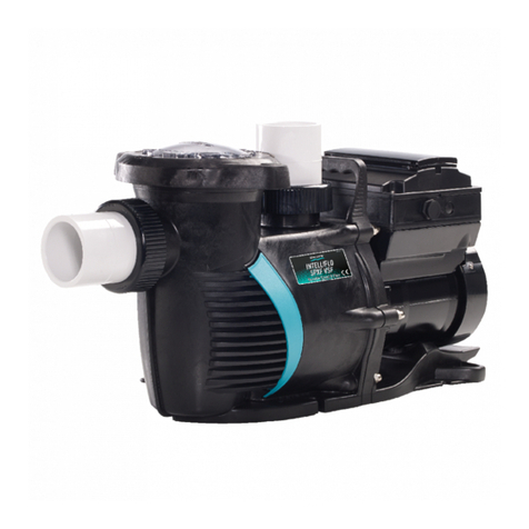
AquaStar Pipeline Pumps PLP300S User manual

My pump is the ☐PLP300S ☐PLP150S or ☐ PLP150B and it was installed on _____________(date)
Installed by ________________________________________________(company/contact)
INSTRUCTION MANUAL
INSTALLATION AND USER'S GUIDE
All rights reserved. Copyright © AquaStar 2022 - U.S. Patent Pending - IN029-081822
FOR YOUR SAFETY
Read, understand and follow all warning notices and instructions before
installing, using, or servicing this pump. Failure to follow warning notices and
instructions may result in property damage, serious injury, or death.
SAVE THESE INSTRUCTIONS
®
ELECTRICAL
HidroShop.mx

HidroShop.mx

AquaStar Pool Products - Pipeline Pump Instructions 3
1.0 IMPORTANT SAFETY INFORMATION 5
1.2 INSTALLATION SAFETY INSTRUCTIONS 6
1.3 USER SAFETY INSTRUCTIONS 8
1.4 SERVICING SAFETY INSTRUCTIONS 10
1.5 PRODUCT DAMAGE WARNINGS 10
2.0 PUMP OVERVIEW 11
3.0 INSTALLATION INSTRUCTIONS 11
3.2 PIPING 13
3.3 ELECTRICAL INSTALLATION 14
4.0 OPERATION INSTRUCTIONS 14
4.1 START UP 15
4.2 DISPLAY INTERFACES 16
4.3 PROGRAMMING INSTRUCTIONS 16
4.3.1 SET TIME 16
4.3.2 SPEED SET UP 16
4.3.3 SCHEDULE SET UP 17
4.3.4 VARIABLE SPEED SET UP 17
4.3.5 LANGUAGE SET UP 17
4.3.6 “NO FLOW” SET UP 18
4.3.7 PUMP PRIMING SET UP 18
4.3.8 FREEZE PROTECTION 18
4.3.9 WIFI FUNCTION 19
4.3.9.1 WIFI DIRECT CONNECTION TO PIPELINE CONNECT APP 19
4.3.9.2 CHANGING SSID AND PASSWORD 19
4.3.10 RS485 COMMUNICATIONS SETUP 19
4.3.11 SYSTEM RESET 20
4.4 PROGRAMMING FLOW CHART 21
5.0 PUMP PERFORMANCE & SPECIFICATIONS 22
6.0 TROUBLESHOOTING 23
7.0 MAINTENANCE 27
7.1 SERVICING 28
8.0 REPLACEMENT PARTS 29
9.0 WARRANTY 31
TABLE OF CONTENTS
HidroShop.mx

4 Pipeline Pump Instructions - AquaStar Pool Products
HidroShop.mx

AquaStar Pool Products - Pipeline Pump Instructions 5
1.0 IMPORTANT SAFETY INFORMATION
IMPORTANT NOTICE
This guide provides installation and operation instructions for this pump. Consult AquaStar Pool
Products, Inc. with any questions regarding this equipment.
Attention Installer: These instructions contain important information about the installation, operation
and safe use of this product. This information should be given to the owner/operator of this equipment after
installation or left on or near the pump. This pump is for use with permanent swimming pools and spas. It
may also be used with hot tubs if so marked.
Attention User: This manual contains important information about the installation, operation,
servicing and safe use of this product. Keep this manual for future use. Replace worn or damaged pump
parts immediately. To reduce risk of injury, do not permit children to use or climb on this product. Closely
supervise children at all times. Components such as the filtration system, pumps, and heaters must be
positioned to prevent children from using them as a means of access to the pool or spa.
Section 1.0 Important Safety Information
HAZARDOUS PRESSURE.
Stand clear of pump and filter
during pump start up. Open filter air
relief valve and stand clear before
starting pump.
Failure to do so could result
in death or serious injury to
service people, users or others.
RISK OF SUCTION ENTRAPMENT.
Keep away from drain covers and
suction outlets. Do not enter water
if drain covers are missing, broken,
loose or not sized for use with this
pump.
Failure to do so could result in
death or serious injury to users
due to pump suction.
RISK OF ELECTRICAL SHOCK
OR ELECTROCUTION.
Always disconnect power to the
pump at the circuit breaker before
servicing the pump.
Failure to do so could result
in death or serious injury to
service people, users or others
due to electric shock.
HidroShop.mx

6 Pipeline Pump Instructions - AquaStar Pool Products
ATTENTION INSTALLER
RISK OF ELECTRICAL SHOCK OR ELECTROCUTION! When installing this electrical equipment, basic safety
precautions provided below should always be followed. FAILURE TO FOLLOW ALL INSTRUCTIONS AND
WARNINGS CAN RESULT IN SERIOUS BODILY INJURY OR DEATH.
RISK OF FIRE, ELECTRIC SHOCK, OR INJURIES TO PERSONS. Install this equipment in accordance with the
National Electric Code® (NEC), the Occupational Safety and Health Act (OSHA), and all applicable laws, codes
and ordinances. Copies of the NEC may be ordered from the National Fire Protection Association, 1 Battery-
march Park, Quincy, Massachusetts USA 02169-7471.
Connect only to a branch circuit protected by a ground-fault circuit-interrupter (GFCI). Contact a
qualified electrician if you cannot verify that the circuit is protected by a GFCI.
Test the GFCI before connecting the pump motor wiring. To test the GFCI, push the test button. The
GFCI should interrupt power. Push the reset button. Power should be restored. If the GFCI fails to operate in
this manner, the GFCI is defective and the problem must be corrected by a qualified service representative
before using.
Connect the motor bonding lug to the pool or spa electrical bonding structure. Failure to bond pump
to pool or spa structure will increase risk for electrocution and could result in injury or death.
Never open the inside of the drive motor enclosure. There is a capacitor bank that holds a 230 VAC charge
even when there is no power to the unit.
This pump is not submersible.
Incorrectly installed equipment may fail, causing severe injury.
Though this product is designed for outdoor use, it is strongly advised to protect the electrical components
from the weather. Select a well drained area, one that will not flood when it rains. It requires free circulation
of air for cooling. Do not install in a damp or non-ventilated location.
Fire and burn hazard. Motors operate at high temperatures and if they are not properly isolated from
any flammable structures or foreign debris they can cause fires, which may cause severe personal injury or
death.
Risk of overheating. If installed within an enclosure or inside hot tub or spa enclosure, adequate ventilation
and free circulation of air must be provided to prevent overheating of the motor.
1.2 INSTALLATION SAFETY INSTRUCTIONS
HidroShop.mx

AquaStar Pool Products - Pipeline Pump Instructions 7
ATTENTION INSTALLER
RISK OF SUCTION ENTRAPMENT. Only install this pump on suction systems that have been evaluated
and found in conformance with the Virginia Graeme Baker Pool & Spa Act, and all warning notices and
instructions that accompany the product. FAILURE TO PROTECT USERS FROM ALL FIVE SUCTION
ENTRAPMENT HAZARDS CAN RESULT IN SERIOUS INJURY OR DEATH.
This pump is not equipped with Automatic Pump Shut-off or Safety Vacuum Release System (SVRS)
protection. It does not protect against body or limb entrapment, disembowelment, or hair entanglement.
RISK OF HAZARDOUS PRESSURE. Before installing this pump, read and follow all warning notices and
instructions that accompany the product. FAILURE TO FOLLOW WARNINGS AND INSTRUCTIONS MAY
RESULT IN PERSONAL INJURY OR DEATH.
Do not install pump on/off switches or controls near filters. Trapped air in the system can cause the filter
lid to be blown off when the pump starts up, which can result in death, or serious injury.
Do not use with storable pools. A permanently-installed pool is constructed in or on the ground or in a
building such that it cannot be readily disassembled for storage. A storable pool is constructed so that it is
capable of being readily disassembled for storage and reassembled to its original integrity.
This pump is capable of high pressure that may exceed the limits of other equipment. Confirm all
equipment installed on the pressure-side of this pump has a working pressure rating of 50 psi or greater. If
the working pressure of other equipment does not meet this requirement, do not install this pump unless
the other equipment is removed or replaced first.
Separation Hazard. Failure to follow safety and operation instructions could result in violent separation of
pump components. Strainer cover must be properly secured to pump housing with strainer cover lock ring.
Pressure Testing Hazards. To minimize the risk of severe injury or death, the pump should not be subjected
to the piping system pressurization test. Do not connect the system to an unregulated city water system or
other external source of pressurized water producing pressures greater than 35 PSI. Local codes may require
the pool piping system to be subjected to a pressure test, however, these requirements are generally not
intended to apply to the pool equipment such as pumps, filters, heaters, or in-line sanitizing systems.
NEVER PRESSURE TEST WITH COMPRESSED AIR!
1.2 INSTALLATION SAFETY INSTRUCTIONS CONTINUED
HidroShop.mx

8 Pipeline Pump Instructions - AquaStar Pool Products
1.3 USER SAFETY INSTRUCTIONS
ATTENTION USER
RISK OF HAZARDOUS PRESSURE. Before installing this pump, read and follow all warning notices and
instructions that accompany the product. FAILURE TO FOLLOW WARNINGS AND INSTRUCTIONS MAY
RESULT IN PERSONAL INJURY OR DEATH.
Before servicing the pump or filter, switch OFF power to the pump by disconnecting the main circuit to
the pump.
This pump is capable of high flow rates that may exceed the limits of other equipment. Do not change
the high speed programming of the pump without confirming all other equipment can handle the
increased flow and pressure.
This pump is not intended for use by persons (including children) of reduced physical, sensory or mental
capabilities, or lack of experience and knowledge, unless they have been given supervision or instruction
concerning the use of the pump by a person responsible for their safety.
RISK OF SUCTION ENTRAPMENT! Keep away from drain covers and suction outlets. Do not enter water
if drain covers are missing, broken, loose or they are not sized for use with this pump. FAILURE TO DO SO
COULD RESULT IN DEATH OR SERIOUS INJURY.
BEFORE USING THIS PUMP CONFIRM THE SUCTION SYSTEM IS COMPLIANT WITH THE VIRGINIA
GRAEME BAKER POOL & SPA SAFETY ACT (VGBA) AND THE FOLLOWING GUIDELINES: THE SUCTION
SYSTEM MUST PROVIDE PROTECTION AGAINST THE HAZARDS OF SUCTION ENTRAPMENT.
This pump is not equipped with Automatic Pump Shut-off or Safety Vacuum Release System (SVRS)
protection. It does not protect against body or limb entrapment, disembowelment, or hair entanglement.
Only install this pump on suction systems that have been evaluated and found in conformance with the
Virginia Graeme Baker Pool & Spa Act, and all warning notices and instructions that accompany the product.
Failure to protect users from all five suction entrapment hazards can result in serious injury or death.
Certified Drain Covers. Before using this pump confirm all drain covers are certified to the U.S. Consumer
Product Safety Standard titled ANSI/APSP/ICC-16 2017, or its predecessor standard ANSI/APSP-16 2011.
Acquire proof of conformance by contacting the drain cover manufacturer who is required to provide a
General Certificate Of Conformity (GCC). Proof of compliance GCC, flow rating specifications, and installation
instructions for drain covers manufactured by AquaStar Pool Products are available at
www.aquastarpoolproducts.com or by calling (877) 768-2717.
HidroShop.mx

AquaStar Pool Products - Pipeline Pump Instructions 9
ATTENTION USER
SUCTION-RELATED HAZARDS:
Hair Entanglement: When the hair tangles or knots in the drain cover, trapping the swimmer
underwater. This hazard is present when the VGBA flow rating of the drain cover is too small for the
pump or pumps.
Limb Entrapment: When a limb is sucked or inserted into an opening resulting in a mechanical
bind or swelling. This hazard is present when a drain cover is missing, broken, loose, cracked or not
properly secured.
Body Entrapment: When a portion of the body is held against the drain cover trapping the
swimmer underwater. This hazard may be present when the drain cover is not VGBA certified,
installation instructions were not followed, or is missing, broken or the cover flow rating is not high
enough for the pump or pumps.
Evisceration/Disembowelment: When a person sits on an open pool (particularly a child wading
pool) or spa outlet and suction is applied directly to the intestines, causing severe intestinal
damage. This hazard may be present when the drain cover is missing, loose, cracked, or not properly
secured.
Identifying VGBA-2017 Compliant Drain Covers. Products compliant with ANSI/APSP/ICC-16 2017
standard will be permanently marked VGBA-2017. This U.S. Consumer Product Safety Standard applies to all
drain covers manufactured or imported into the United States on or after the law’s May 24, 2021 effective
date.
Drain covers compliant with the previous version of the U.S. Consumer Product Safety Standard may also be
used in compliance with the VGBA (those manufactured or imported before May 24, 2021) provided they
were installed according to their installation instructions and have not exceeded their installed service life.
Drain covers compliant with the previous version of the standard will be marked with one or more of
the following; ANSI/APSP-16 2011; VGB-2008, or ASME/ANSI A112.19.8 - 2007, 2008a, or 2009b.
Drain covers with no markings and those marked with “ASME/ANSI A112.19.8M” are not VGBA
compliant and should be replaced.
Drain Cover Service Life. REPLACE OLD DRAIN COVERS BEFORE USING THIS PUMP. Drain covers have a
limited service life, losing important strength over time because of sunlight and chemicals. They should be
replaced before they expire, and they must be replaced if missing, broken, loose, or are not certified to one
of the VGBA drain cover standards identified above. VGBA compliant drain covers will also be marked with
a service life designation, e.g., LIFE: 5 YEARS. This is to help assure drain covers are strong enough to protect
users from the pump’s suction over time.
DRAIN COVER INSTALLATION NOTES:
_________________________________________________________________________________________
_________________________________________________________________________________________
_________________________________________________________________________________________
1.3 USER SAFETY INSTRUCTIONS CONTINUED
HidroShop.mx

10 Pipeline Pump Instructions - AquaStar Pool Products
ATTENTION SERVICER
HAZARDOUS PRESSURE. Before servicing this pump, read and follow all warning notices and instructions
that accompany the product. FAILURE TO FOLLOW WARNINGS AND INSTRUCTIONS MAY RESULT IN
PERSONAL INJURY OR DEATH.
Before servicing the pump or filter, switch OFF power to the pump by disconnecting the main circuit to
the pump.
This pump is capable of high flow rates that may exceed the limits of other equipment. Do not change the
high speed programming of the pump without confirming all other equipment can handle the increased
flow.
This pump is not intended for use by persons (including children) of reduced physical, sensory or mental
capabilities, or lack of experience and knowledge, unless they have been given supervision or instruction
concerning the use of the pump by a person responsible for their safety.
NEVER run the pump dry! Running the pump dry will damage seals, causing leakage and flooding. Fill the
pump with water before starting.
Repair suction system air leaks. Air entering the pump may collect in filters causing pressurized air hazards
that could damage the pump, reduce pump performance, increase pump noise, and decrease the life of the
pump. Air can enter the pump if the pump unions and strainer basket lid O-Ring are not clean, lubricated
and properly tightened. Suction-side control valves, air venting Safety Vacuum Release Systems (SVRS), and
Vacuum-Limiting Vent Systems may also be the source of air entering the pump.
1.4 SERVICING SAFETY INSTRUCTIONS
1.5 PRODUCT DAMAGE WARNINGS
HidroShop.mx

AquaStar Pool Products - Pipeline Pump Instructions 11
The AquaStar PipeLine Variable Speed Pump can be programmed to run at specific speeds and time intervals
for maximum operating efficiency and energy conservation.
• The pump can be adjusted from the control panel to
run at any speed between 800 RPM to 3400 RPM for
different applications.
• The pump comes equipped with a programmable
freeze protection function that will circulate water in
the pool when temperature reaches a set point.
• Pump control panel will display Over Voltage, Under
Voltage, Over Current, Overheating and No Water Flow
Warnings.
• Programmable self-priming settings allow for priming
customization for each unique pool.
• Compatible with most cleaning systems, filters, and jet
action spas.
2.0 PUMP OVERVIEW
EXTERNAL CONTROL
AquaStar PipeLine Pumps come with optional Smart
Communication Functionality.
• Smart pump models come equipped with a RS-
485 connection port which, along with AquaStar’s
Communication Module PLCM100 (sold separately),
can communicate with Pentair® and Jandy®
Automation Systems.*
• Smart pump models come equipped with WiFi
capability that allows full control of pump speeds and
schedules with the free AquaStar PipeLine Connect
App.
• MOTOR FEATURES
• High-Efficiency Permanent Magnet Synchronous
Motor (PMSM).
• Operates at lower temperatures due to high
efficiency.
• Designed to withstand outdoor environment.
• Totally Enclosed Fan Cooled (TEFC) Motor.
• 56 Square Flange.
• Low noise.
DRIVE FEATURES
• High-efficiency speed controls.
• Thermostat driven freeze protection.
• Customizable variable flow setting for water features.
• Built in run time scheduling.
• No flow protection.
3.0 INSTALLATION INSTRUCTIONS
Only a qualified plumbing professional should install the PipeLine Pump. Refer to“Installation Safety
Instructions”on pages 6-7 for additional installation and safety information.
Note: The PipeLine Pump cannot be connected in series with other pumps.
CAUTION: The pump and its packaged components may have shifted during transport. When unpacking
the pump at the installation site, carefully remove the pump to avoid damaging it. Inspect the pump for any
damage before beginning the following installation procedures.
FIGURE 1
*Pentair®and Jandy®are registered trademarks of Pentair Flow Services AG and Zodiac Pool Systems, LLC., respectively
Strainer Lid & Locking Rings
Pump Union & Nut
Motor Fan Cover
Drive Display Cover
Motor Drive
Vibration Dampening
Motor Support
Communication Port
Wiring Compartment
HidroShop.mx

12 Pipeline Pump Instructions - AquaStar Pool Products
Note: Do not install this pump within an outer enclosure or beneath the skirt of a hot tub or spa unless marked
accordingly.
Note: Ensure that the pump is mechanically secured to the equipment pad.
Be sure the pump location meets the following requirements:
1. Install the pump as close to the pool or spa as possible. To reduce friction loss and improve efficiency, use short,
direct suction piping returns.
2. Install a minimum of 5 feet (1.52 meters) from the inside wall of the pool and spa. Canadian installations require a
minimum of 9.8 feet (3 meters) from pool water level.
3. Install the pump a minimum of 3 feet (.9 meters) from the heater outlet.
4. Do not install the pump more than 8 feet (2.4 meters) above the water level.
5. Install the pump in a well ventilated location protected from excessive moisture (i.e., rain gutter downspouts,
sprinklers, etc.)
6. Install the pump with a rear clearance of at least 3-inches (76.2 mm) so that the motor can be removed easily for
maintenance and repair. See Figure 2.
7. Install the pump on a level, vibration free surface.
8. Make sure that floor drainage is adequate to prevent flooding.
3.1 PUMP LOCATION
3.0 INSTALLATION INSTRUCTIONS CONTINUED
Install all electrical controls at equipment pad, such as on/off switches, timers, and control systems,
etc. to allow the operation (startup, shutdown, or servicing) of any pump or filter so the user does
not place any portion of his/her body over or near the pump strainer lid, filter lid or valve closures. This installation
should allow the user enough space to stand clear of the filter and pump during system start-up, shut down or
servicing of the system filter.
General Installation Information
• All work must be performed by a qualified service professional, and must conform to all national, state, and local
codes.
• Install to provide drainage of compartment for electrical components.
• The pump will only function correctly if it is properly sized to the specific application and properly installed.
WARNING: Pumps improperly sized or installed or used in applications other than for which the pump was intended
can result in severe personal injury or death. These risks may include but not be limited to electric shock, fire, flooding,
suction entrapment or severe injury or property damage caused by a structural failure of the pump or other system
component.
HidroShop.mx

AquaStar Pool Products - Pipeline Pump Instructions 13
3.3 ELECTRICAL INSTALLATION
FIGURE 3
3.2 PIPING
1. For improved pool plumbing efficiency, it is recommended to
use the largest pipe size available. Pipeline Pumps come with
a recommended 2-1/2”union.
2. Plumbing size on the suction side of the pump should be the
same or larger than the return line size.
3. Total plumbing run on the suction side of the pump should
be as short as possible in order minimize pump cavitation.
4. AquaStar recommends plumbing the suction side of the
pump with a straight run of pipe equal to (5) times the pipe
diameter before any valve, elbow, or tee. See Figure 2.
Example: A 2 1/2” pipe requires a 12.5”(318 mm) straight run
5. For most installations, AquaStar recommends installing a
valve on both the pump suction and return lines so that the
pump can be isolated during routine maintenance.
Note: Do not install 90 elbows directly into the pump inlet or outlet.
3 IN.
(7.6 CM)
MINIMUM
FIGURE 2
SHOCK OR ELECTROCUTION. This pump must be installed by a licensed or certified
electrician or a qualified service professional in accordance with the National
Electrical Code and all applicable local codes and ordinances. Improper installation
will create an electrical hazard which could result in death or serious injury to users, installers, or others due
to electrical shock, and may also cause damage to property.
Always disconnect power to the pump at the circuit breaker before servicing the pump. Failure to do
so could result in death or serious injury to service people, users or others due to electric shock.
Read all servicing instructions before working on the pump.
Note: ALWAYS reinstall the cover onto the field wiring compartment when leaving the pump
unsupervised during servicing. This will prevent foreign matter (i.e. rainwater, dust, etc.) from
accumulating in the drive.
Note: When connecting the pump to an automation
system, continuous power must be supplied to the
pump by connecting it directly to the circuit breaker.
When using an automation system, be sure that no
other lights or appliances are on the same circuit.
Note: When controlling the pump with a relay, or
timer be sure to use two-pole devices so that power
is always supplied and removed to both HOT LINES
simultaneously
Note: If GFCI circuit breaker protection is required, the pump should be ground wired on its own
independent circuit. AquaStar Pool Products recommends using a Siemens Class A Double Ground
Fault Circuit Interrupter.
LINE 1
LINE 2
GROUND
HidroShop.mx

14 Pipeline Pump Instructions - AquaStar Pool Products
Power Supply Wiring:
1. Ensure that the supply voltage is within required range listed on the motor nameplate.
2. Make sure that the pump is disconnected from power source and all electrical breakers are switched off.
3. Unscrew and remove the wiring compartment cover on the side of the motor. Be sure not to remove the red
gasket seal.
4. Make the required wiring connections inside of this wiring compartment per the National Electric Code and any
required local codes. See Figure 3 for connection locations.
5. Connection terminals labeled L1 & L2 are the two hot lines and should be connected to a properly protected
supply circuit using the correct wire size and type as per the National Electric Code.
6. Connection terminal labeled with the ground symbol should be connected to an electrical service ground using
the correct wire size and type as per the National Electric Code.
7. Be sure to cut and strip wires to the proper length to prevent wire shorting.
8. Use an appropriate watertight strain relief in the ½” NPT connection on the bottom of the wiring compartment in
order to create a permanent electrical connection.
9. Once wiring is complete, reinstall the wiring compartment cover and tighten the 3 cover screws. Be sure the red
gasket seal has remained in place.
Bonding Connection:
1. Bond the motor to the pool structure using a solid copper conductor
and the Bonding Lug on the side of the motor, as shown in Figure 4, in
accordance with the National Electrical Code.
2. Use no smaller than 8 AWG conductor for US installations and no smaller
than 6 AWG conductor for Canadian installations.
3. Connect this bonding wire to all metal parts of the swimming pool, spa,
and/or hot tub. This includes, but is not limited to, any and all metal
structural components, all electrical equipment, all metal conduit, pool
heaters, and any metal piping within 5 feet (1.52 meters) of the inside walls
of the swimming pool, spa, and/or hot tub. FIGURE 4
4.0 OPERATION INSTRUCTIONS
Always STOP PUMP and RELEASE ALL PRESSURE from pump and piping system before
servicing. NEVER tighten or loosen bolts while the pump is operating. Do not block the pump
suction.
HAZARDOUS PRESSURE: STAND CLEAR OF PUMP AND FILTER DURING START UP.
Circulation systems operate under high pressure. When any part of the circulating system ( i.e.
locking ring, pump, filter, valves, etc.) is serviced, air can enter the system and become pressurized.
Pressurized air can cause the pump housing cover, filter lid, and valves to violently separate which
can result in severe personal injury or death. Filter tank lid and strainer cover must be property
secured to prevent violent separation. Stand clear of all circulation system equipment when
turning on or starting up pump.
Before servicing equipment, make note of the filter pressure. Be sure that all controls are set to ensure the system
cannot inadvertently start during service.
Turn off all power to the pump.
3.3 ELECTRICAL INSTALLTION CONTINUED
Bonding Lug
HidroShop.mx

AquaStar Pool Products - Pipeline Pump Instructions 15
Time: Built-in time clock.
Current Speed: Shows operating
speed. Expressed in RPM.
Scheduled Program: Shows
current operating schedule.
Current Running Speed: Shows
current operating speed. Four pre-
set speeds available.
LCD Display back-light will switch
off after 60 seconds if no button is
pressed. It can be turned on again
by pressing any button.
4.1 START UP
MANUAL FILL
1. Ensure power to the pump is off at the breaker and that the motor is not running dry.
2. Ensure that the two drain plugs are installed and tight.
3. Close valves on the inlet and outlet side of the pump.
4. Turn the locking ring counter-clockwise to remove the strainer lid and locking ring
5. Fill the basket side of the pump housing with water. Slowly let water fill the impeller side of the pump
housing by continuing to add water until basket side is completely full.
6. Reinstall the strainer lid and locking ring, turning clockwise to hand tighten.
PRIMING THE PUMP
1. With the strainer lid installed, open the valves on inlet and outlet side of the pump.
2. Open the air bleed valve on the pool filter.
3. Turn on power to the pump at the breaker.
4. Be sure the control panel display is active and press the“Run”button to begin priming. See Figure 5.
5. Close the air bleed valve on the pool filter once all air has escaped.
6. The pump default prime settings are 2900 RPM for 2 minutes. If the pump is not fully primed after this 2 minute
cycle, press the“Speed 4” button, which is preprogrammed at 2900 RPM and let the pump continue to run at this
speed until priming is complete.
7. For instructions on how to customize your prime settings, see section 4.3.7 “Pump Priming Set Up.”
8. If the pump cannot reach full flow prime when running at 3400 RPM within 10 minutes, stop the pump and see
the Troubleshooting Guide in section 6.
FIGURE 5
IMPORTANT: Place filter manual air relief valve in the open position and wait for all pressure in the
system to be relieved. Before starting the system, fully open the manual air relief valve and place all system valves
in the “open”position to allow water to flow freely from the tank and back to the tank. Stand clear of all equipment and
start the pump.
IMPORTANT: Do not close filter manual air relief valve until all pressure has been discharged from the
valve and a steady stream of water appears. Observe filter pressure gauge and be sure it is not higher than the
pre-service condition.
4.0 OPERATION INSTRUCTIONS CONTINUED
HidroShop.mx

16 Pipeline Pump Instructions - AquaStar Pool Products
4.2 DISPLAY INTERFACES
Up
Increase value
Down
Decrease value
Left
Move cursor left
Right
Move cursor right
Enter
Enter sub-menus or
save setting
Speed 1
Select Speed 1
Preset to 900 RPM
Speed 2
Select Speed 2
Preset to 1500 RPM
Speed 3
Select Speed 3
Preset to 2500 RPM
Speed 4
Select Speed 4
Preset to 2900 RPM
Start
Start the motor
Stop
Stop the Motor
Menu
Enter settings menu,
only accessible when the
motor is not running
ESC
Back / Cancel
4.3 PROGRAMMING INSTRUCTIONS
Note: The internal system clock is used to program operating schedules. If the power supply is disconnected, the
controller memory and programmed settings will be maintained for approximately 7 days.
Note: Ensure the pump is in the off position before modifying any pump setting.
4.3.1 SET TIME
Time is set using a 24 hour clock (hr:min)
• Press “Menu”button to enter the settings menu.
• Use buttons “Up” and “Down” to highlight “Time” and press “Enter.”
• Press “Enter” again to modify, then using“Up,”“Down,”“Left,” and “Right” buttons, set local time and press “Enter.”
• Press “ESC” button to return to the previous screen or repeatedly press to return to the home screen.
4.3.2 SPEED SET UP
There are 4 speed settings available. To program speeds:
• Press “Menu”button to enter the settings menu.
• Use buttons“Up”and “Down” to highlight “Speeds”option and press“Enter.”
• Use buttons“Up”and “Down” to highlight desired speed to modify and press “Enter.”
• Press “Enter” again to modify, then using“Up”and “Down” buttons, adjust the speed to desired RPM and press “Enter.”
• Press “ESC” button to return to the previous screen or repeatedly press to return to the home screen.
PUMP STOPPED
RUNNING SPEED COMMUNICATION ERROR
UNDER VOLTAGE MENU SETTINGS
HidroShop.mx

AquaStar Pool Products - Pipeline Pump Instructions 17
4.3.3 SCHEDULE SET UP
Note: The pump is supplied with the pre-set schedules for an easier start-up. If necessary, these parameters can be
changed. Pre-set schedule settings are as follows:
Schedule 1 - Disabled / Time on 8:30 / Time off 11:30 / Speed 1
Schedule 2 - Disabled / Time on 14:30 / Time off 17:30 / Speed 1
Schedule 3 - Disabled / Time on 19:30 / Time off 21:30 / Speed 1
To enable or disable a schedule:
• Press “Menu”button to enter the settings menu.
• Use buttons“Up”and “Down” to highlight the “Schedules” option and press “Enter.”
• Use buttons“Up”and “Down” to highlight desired schedule to modify and press “Enter.”
• Use buttons“Up”and “Down” to highlight the “Function” option and press “Enter.”
• Press “Enter” again to modify, then using“Up”and “Down” buttons highlight “Enable”or“Disable” and press “Enter”
to save.
• Press “ESC” button to return to the previous screen or repeatedly press to return to the home screen.
To adjust “Time On” or “Time Off” settings:
• Press “Menu”button to enter the settings menu.
• Use buttons“Up”and “Down” to highlight the “Schedules” option and press “Enter.”
• Use buttons“Up”and “Down” to highlight desired schedule to modify and press “Enter.”
• Use buttons“Up”and “Down” to highlight the “Time On” or “Time Off” option and press“Enter.”
• Use buttons“Up,”“Down,”“Left,” and “Right” to set desired schedule time and press “Enter” to save.
• Press “ESC” button to return to the previous screen or repeatedly press to return to the home screen.
Note: Schedule settings can also be adjusted within the AquaStar Pipeline Connect App.
4.3.4 VARIABLE SPEED SET UP
This function allows the pump to cycle through a predefined speed profile in order to create varying flow patterns
which are particularly useful for creating visual effects on water features.
To adjust Variable Speed settings:
• Press “Menu”button to enter the settings menu.
• Use buttons“Up”and “Down” to highlight the “Variable Speed” option and press “Enter.”
• Use buttons“Up”and “Down” to highlight:
• The “Function” option and press “Enter” to “Enable” or “Disable” this feature.
• The “Time On” option to schedule the time to start this function.
• The “Time Off” option to schedule the time to stop this function.
• The “Min Speed” option to adjust the minimum speed of the flow profile.
• The “Max Speed” option to adjust the maximum speed of the flow profile.
• The “Step”option to adjust the RPM increments the flow profile will step between.
• The “Rhythm”option to adjust the time, in seconds, that the profile will cycle through each step.
• Use buttons“Up,”“Down,”“Left,” and “Right” to adjust these settings and press“Enter” to save.
• Press “ESC” button to return to the previous screen or repeatedly press to return to the home screen.
4.3.5 LANGUAGE SET UP
• Press “Menu”button to enter the settings menu.
• Use buttons“Up”and “Down” to highlight the “Language”option and press “Enter.”
•The symbol “>” indicates the language in use.
• Press “Enter” again to enter into editing mode and use“Up”and “Down”buttons to select the required language.
4.3 PROGRAMMING INSTRUCTIONS CONTINUED
HidroShop.mx

18 Pipeline Pump Instructions - AquaStar Pool Products
4.3 PROGRAMMING INSTRUCTIONS CONTINUED
4.3.5 LANGUAGE SET UP (continued)
• Press “Enter” to save the setting. The interface will be shown in the selected language immediately. Otherwise,
press “ESC” to exit the editing mode.
• Press “ESC” button to return to the previous screen or repeatedly press to return to the home screen.
4.3.6 “NO FLOW” SET UP
This function stops the pump automatically when it detects a “No Flow” condition. This feature is only available for
motor speeds of 1800 RPM or more and is set up through the following parameters:
• Press “Menu”button to enter the settings menu.
• Use buttons“Up”and “Down” to highlight the “No-Flow” option and press “Enter.”
• Use buttons“Up”and “Down” to highlight:
• The “Function” option and press “Enter” to “Enable”or “Disable” this feature (it is disabled by default).
• The “Alarm Time”option to set the time frame that defines a No-Flow condition. Min. setting is 5 minutes.
• The “Sensitivity” option to adjust the detection sensitivity expressed in a %. Min. setting is 0.01%.
• Press “Enter” to edit and then use “Up,”“Down,”“Left,” and “Right” buttons to adjust these settings and press “Enter”
to save.
• Press “ESC” button to return to the previous screen or repeatedly press to return to the home screen.
Note: If system detects a “No Flow” condition the motor will stop and the display will show the Fault Code “NF”
4.3.7 PUMP PRIMING SET UP
\This function creates a self priming program to be run whenever pump is started. To customize self priming settings:
• Press “Menu”button to enter the settings menu.
• Use buttons“Up”and “Down” to highlight the “Priming” option and press “Enter.”
• Use buttons“Up”and “Down” to highlight: 9
• The “Function” option and press “Enter” to “Enable” or “Disable” this feature
(which is set to “Enabled” by default).
• The “Priming Time” option to set the time, in minutes, that the pump will run to achieve prime.
Default time: 2 minutes, Min. Time: 1 minute, Max. Time: 20 minutes.
• The “Priming Speed” option to adjust speed the pump will run at to achieve prime.
Default Speed: 2900 RPM, Min. Speed: 2900 RPM, Max. Speed: 3400 RPM
• Press “Enter” to edit and then use “Up,”“Down,”“Left,” and “Right” buttons to adjust these settings and press “Enter”
to save.
• Press “ESC” button to return to the previous screen or repeatedly press to return to the home screen.
4.3.8 FREEZE PROTECTION
This function turns the pump on when the outside temperature is below a set point to prevent water from freezing:
• Press “Menu”button to enter the settings menu.
• Use buttons“Up”and “Down” to highlight the “Freeze”option and press“Enter.”
• Use buttons“Up”and “Down” to highlight:
• The “Function” option and press “Enter” to “Enable”or “Disable” this feature (which is set to “Enabled” by default)
• The “Duration”option to set the run time, in hours, that the pump will run after triggered.
Default time: 1 hours, Min. Time: 1 hour, Max. Time: 8 hours.
• The “Speed” option to adjust speed the pump will run at to prevent freeze.
Default Speed: 1700 RPM, Min. Speed: 900 RPM, Max. Speed: 3400 RPM
• The “Temperature”option to adjust temperature that will trigger the pump to run the freeze program.
Default Temperature: 4° C (39° F), Min. Temperature: 0° C (32° F), Max. Temperature: 10° C (50° F)
• Press“Enter” to edit and then use “Up,”“Down,”“Left,”and “Right” buttons to adjust these settings and press“Enter” to save.
• Press “ESC” button to return to the previous screen or repeatedly press to return to the home screen.
HidroShop.mx

AquaStar Pool Products - Pipeline Pump Instructions 19
4.3 PROGRAMMING INSTRUCTIONS CONTINUED
4.3.9 WIFI FUNCTION
This function is only available on Smart Model PipeLine Pumps. This feature allows for connection to the AquaStar
PipeLine Connect Mobile App.
• Press “Menu”button to enter the settings menu.
• Use buttons“Up”and “Down” to highlight the “WiFi” option and press “Enter.”
• Use buttons “Up” and “Down” to highlight the “Function” option and press “Enter” to “Enable” or “Disable” this
feature
(which is set to “Enabled” by default).
• Selecting the “WiFi Reset” option and pressing“Enter” will return the WiFi settings to factory default.
• Press “ESC” button to return to the previous screen or repeatedly press to return to the home screen.
4.3.9.1 WIFI DIRECT CONNECTION TO PIPELINE CONNECT APP
Note: Pipeline Connect App only works with “Smart”WiFi enabled Pipeline Pumps
• Install the “AquaStar Pipeline Connect App”from App Store or Play Store.
• Ensure the WiFi function is “Enabled” (see previous section 4.3.9).
• Go to Wi-Fi setting on mobile device and select the network “EPVSPV-WiFi” and enter the password “VS_ _PUMP”
• Open the “AquaStar Pipeline Connect App” and follow prompts.
Note: While connected to the pump WiFi Direct Network, Internet access is disabled.
4.3.9.2 CHANGING SSID AND PASSWORD
To change the SSID and password for the WiFi Direct network:
• While connected to the “EPVSPV-WiFi” network enter the IP address “192.168.8.1:88” into a web browser.
• Select SSID & Password on the right side of the screen.
• Enter your new SSID Name, Password, and Repeat Password then press“Submit.”
• Disconnect from “EPVSPV-WiFi” network and reconnect to the newly named network.
WiFi Specifications:
Compliant to IEEE 802.11b/b/n
1T1R 2.4GHz with support for a 150Mbps PHY data rate
Security: WEP64/128, TKIP, AES, WPA, WPA2, WAPI
AP and STA mode
25m distance transmission
Built-in antenna
4.3.10 RS485 COMMUNICATIONS SETUP
This pump can be controlled by external automation systems via an RS485 connection. This feature only works in
conjunction with an AquaStar PipeLine Communication Module (p/n PLCM100):
• Press “Menu”button to enter the settings menu.
• Use buttons“Up”and “Down” to highlight the “RS485” option and press “Enter.”
• Baud rate is set to 9600 bps. Do not modify this setting.
• Use buttons“UP” and “Down” to highlight the “Replica Address”(formerly called“Slave Address”) and press“Enter”
to modify.
• The Replica Address (formerly called Slave Address) is a unique pump ID to be used on external automation
systems when multiple pumps are being controlled. This is set to “1” by default.
• If multiple pumps are being controlled on the same system ensure that each pump has its own unique Replica
Address (formerly called Slave Address).
• Press “Enter” to edit and then use buttons “Up,”“Down,”“Left,” and “Right” to adjust these settings and press
“Enter” to save.
• Press “ESC” button to return to the previous screen or repeatedly press to return to the home screen.
HidroShop.mx

20 Pipeline Pump Instructions - AquaStar Pool Products
4.3 PROGRAMMING INSTRUCTIONS CONTINUED
RS485 Specifications:
Max baud rate 9600bps
MODBUS Protocol, Support function code 3,4,6, and 16
1-247 Replica address
Isolated A/B data bus, without 120 ohm terminal resistor
4.3.11 SYSTEM RESET
This function will reset all the user settings to the factory default and can not be undone.
• Press “Menu”button to enter the settings menu.
• Use buttons“Up”and “Down” to highlight the “RESET” option and press “Enter.”
• Press “Enter” to reset system.
HidroShop.mx
Other manuals for Pipeline Pumps PLP300S
1
This manual suits for next models
2
Table of contents
Popular Swimming Pool Pump manuals by other brands

Simer
Simer 2115 owner's manual

Speck
Speck Badu EcoMV Installation, operating and maintenance guide

Pentair Pool Products
Pentair Pool Products Pump Waterfall Operation and service manual

STA-RITE
STA-RITE MAX-E-PRO owner's manual

Pahlen
Pahlen EcoVISE user manual

Madimack
Madimack ELITE VS installation manual